2008 SUZUKI SWIFT front wheel speed sensor
[x] Cancel search: front wheel speed sensorPage 58 of 1496
Downloaded from www.Manualslib.com manuals search engine 1A-8 Engine General Information and Diagnosis:
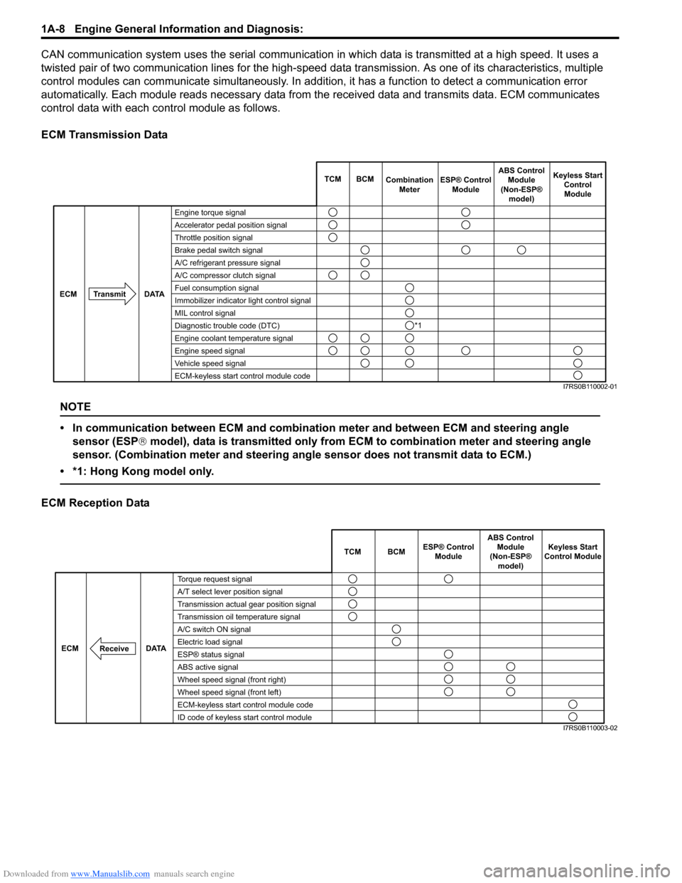
CAN communication system uses the serial communication in which data is transmitted at a high speed. It uses a
twisted pair of two communication lines for the high-speed da ta transmission. As one of its characteristics, multiple
control modules can communicate simultaneously. In addition, it has a function to detect a communication error
automatically. Each module reads necessary data from the received data and transmits data. ECM communicates
control data with each control module as follows.
ECM Transmission Data
NOTE
• In communication between ECM and combination meter and between ECM and steering angle sensor (ESP ® model), data is transmitted only from ECM to combination meter and steering angle
sensor. (Combination meter and steering angle sensor does not transmit data to ECM.)
• *1: Hong Kong model only.
ECM Reception Data
Engine torque signal
Accelerator pedal position signal
Throttle position signal
Brake pedal switch signal
A/C refrigerant pressure signal
A/C compressor clutch signal
Fuel consumption signal
Immobilizer indicator light control signal
MIL control signal
Diagnostic trouble code (DTC)
Engine coolant temperature signal
Engine speed signal
Vehicle speed signal
ECM-keyless start control module code TCM BCM
Combination
Meter Keyless Start
ControlModule
Transmit DATA
ECM
ESP® Control
Module ABS Control
Module
(Non-ESP® model)
*1
I7RS0B110002-01
TCM BCM Keyless Start
Control Module
DATA
ECM
Torque request signal
A/T select lever position signal
Transmission actual gear position signal
Transmission oil temperature signal
A/C switch ON signal
Electric load signal
ESP® status signal
ABS active signal
Wheel speed signal (front right)
Wheel speed signal (front left)
ECM-keyless start control module code
ID code of keyless start control module
Receive
ABS Control
Module
(Non-ESP® model)
ESP® Control
Module
I7RS0B110003-02
Page 178 of 1496
Downloaded from www.Manualslib.com manuals search engine 1A-128 Engine General Information and Diagnosis:
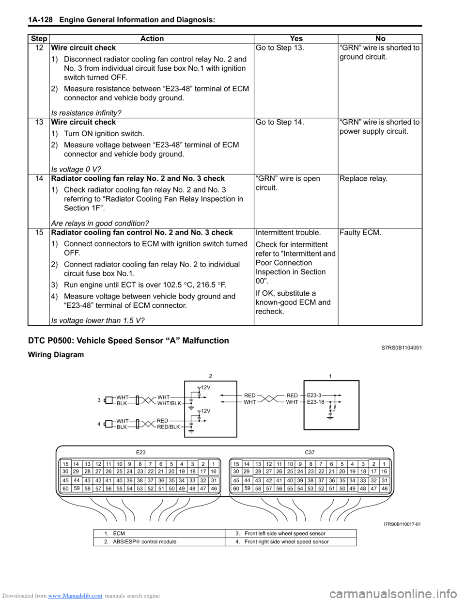
DTC P0500: Vehicle Speed Sensor “A” MalfunctionS7RS0B1104051
Wiring Diagram12
Wire circuit check
1) Disconnect radiator cooling fan control relay No. 2 and
No. 3 from individual circuit fuse box No.1 with ignition
switch turned OFF.
2) Measure resistance between “E23-48” terminal of ECM connector and vehicle body ground.
Is resistance infinity? Go to Step 13. “GRN” wire is shorted to
ground circuit.
13 Wire circuit check
1) Turn ON ignition switch.
2) Measure voltage between “E23-48” terminal of ECM
connector and vehicle body ground.
Is voltage 0 V? Go to Step 14. “GRN” wire is shorted to
power supply circuit.
14 Radiator cooling fan relay No. 2 and No. 3 check
1) Check radiator cooling fan relay No. 2 and No. 3
referring to “Radiator Coolin g Fan Relay Inspection in
Section 1F”.
Are relays in good condition? “GRN” wire is open
circuit.
Replace relay.
15 Radiator cooling fan control No. 2 and No. 3 check
1) Connect connectors to ECM with ignition switch turned
OFF.
2) Connect radiator cooling fan relay No. 2 to individual circuit fuse box No.1.
3) Run engine until ECT is over 102.5 °C, 216.5 °F.
4) Measure voltage between vehicle body ground and “E23-48” terminal of ECM connector.
Is voltage lower than 1.5 V? Intermittent trouble.
Check for intermittent
refer to “Intermittent and
Poor Connection
Inspection in Section
00”.
If OK, substitute a
known-good ECM and
recheck.
Faulty ECM.
Step Action Yes No
E23
C37
34
1819
567
10
11
17
20
47 46
495051
2122
52 16
25 9
24
14
29
55
57 54 53
59
60 58 2
262728
15
30
56 4832 31
34353637
40
42 39 38
44
45 43 41 331
1213
238
34
1819
567
10
11
17
20
47 46
495051
2122
52 16
25 9
24
14
29
55
57 54 53
59
60 58 2
262728
15
30
56 4832 31
34353637
40
42 39 38
44
45 43 41 331
1213
238
E23-3E23-18REDWHTREDWHTWHT/BLKWHTBLKWHT
BLKWHTREDRED/BLK
12V
12V
3
4 21
I7RS0B110017-01
1. ECM
3. Front left side wheel speed sensor
2. ABS/ESP® control module 4. Front right side wheel speed sensor
Page 438 of 1496
Downloaded from www.Manualslib.com manuals search engine 2B-5 Front Suspension:
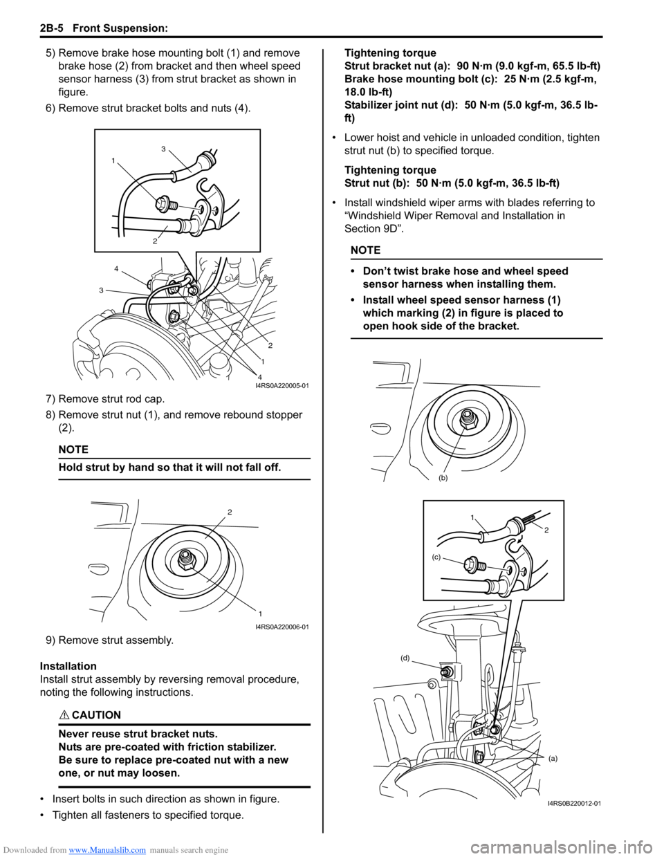
5) Remove brake hose mounting bolt (1) and remove brake hose (2) from bracket and then wheel speed
sensor harness (3) from strut bracket as shown in
figure.
6) Remove strut bracket bolts and nuts (4).
7) Remove strut rod cap.
8) Remove strut nut (1), and remove rebound stopper (2).
NOTE
Hold strut by hand so th at it will not fall off.
9) Remove strut assembly.
Installation
Install strut assembly by reversing removal procedure,
noting the following instructions.
CAUTION!
Never reuse strut bracket nuts.
Nuts are pre-coated with friction stabilizer.
Be sure to replace pre-coated nut with a new
one, or nut may loosen.
• Insert bolts in such direction as shown in figure.
• Tighten all fasteners to specified torque. Tightening torque
Strut bracket nut (a): 90 N·m (9.0 kgf-m, 65.5 lb-ft)
Brake hose mounting bolt (c): 25 N·m (2.5 kgf-m,
18.0 lb-ft)
Stabilizer joint nut (d): 50 N·m (5.0 kgf-m, 36.5 lb-
ft)
• Lower hoist and vehicle in unloaded condition, tighten strut nut (b) to specified torque.
Tightening torque
Strut nut (b): 50 N·m (5.0 kgf-m, 36.5 lb-ft)
• Install windshield wiper arms with blades referring to
“Windshield Wiper Removal and Installation in
Section 9D”.
NOTE
• Don’t twist brake hose and wheel speed sensor harness when installing them.
• Install wheel speed sensor harness (1) which marking (2) in figure is placed to
open hook side of the bracket.
1 3
2
2
1
4
4
3
I4RS0A220005-01
2
1
I4RS0A220006-01
(d) (a)
(b)
(c)
1
2
I4RS0B220012-01
Page 441 of 1496
Downloaded from www.Manualslib.com manuals search engine Front Suspension: 2B-8
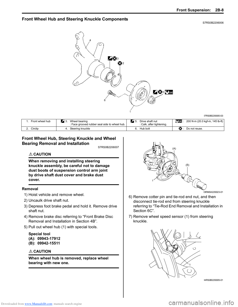
Front Wheel Hub and Steering Knuckle ComponentsS7RS0B2206006
Front Wheel Hub, Steering Knuckle and Wheel
Bearing Removal and Installation
S7RS0B2206007
CAUTION!
When removing and installing steering
knuckle assembly, be careful not to damage
dust boots of suspension control arm joint
by drive shaft dust cover and brake dust
cover.
Removal1) Hoist vehicle and remove wheel.
2) Uncaulk drive shaft nut.
3) Depress foot brake pedal and hold it. Remove drive shaft nut.
4) Remove brake disc referring to “Front Brake Disc Removal and Installa tion in Section 4B”.
5) Pull out wheel hub (1) with special tools.
Special tool
(A): 09943-17912
(B): 09942-15511
CAUTION!
When wheel hub is removed, replace wheel
bearing with new one.
6) Remove cotter pin and tie-rod end nut, and then disconnect tie-rod end from steering knuckle
referring to “Tie-Rod End Removal and Installation in
Section 6C”.
7) Remove wheel speed sensor (1) from steering knuckle.
I7RS0B220005-03
1. Front wheel hub 3. Wheel bearing
: Face grooved rubber seal side to wheel hub. 5. Drive shaft nut
: Calk, after tightening. : 200 N
⋅m (20.0 kgf-m, 145 lb-ft)
2. Circlip 4. Steering knuckle 6. Hub bolt: Do not reuse.
I3RM0A220023-01
1
I4RS0B220005-01
Page 444 of 1496
Downloaded from www.Manualslib.com manuals search engine 2B-11 Front Suspension:
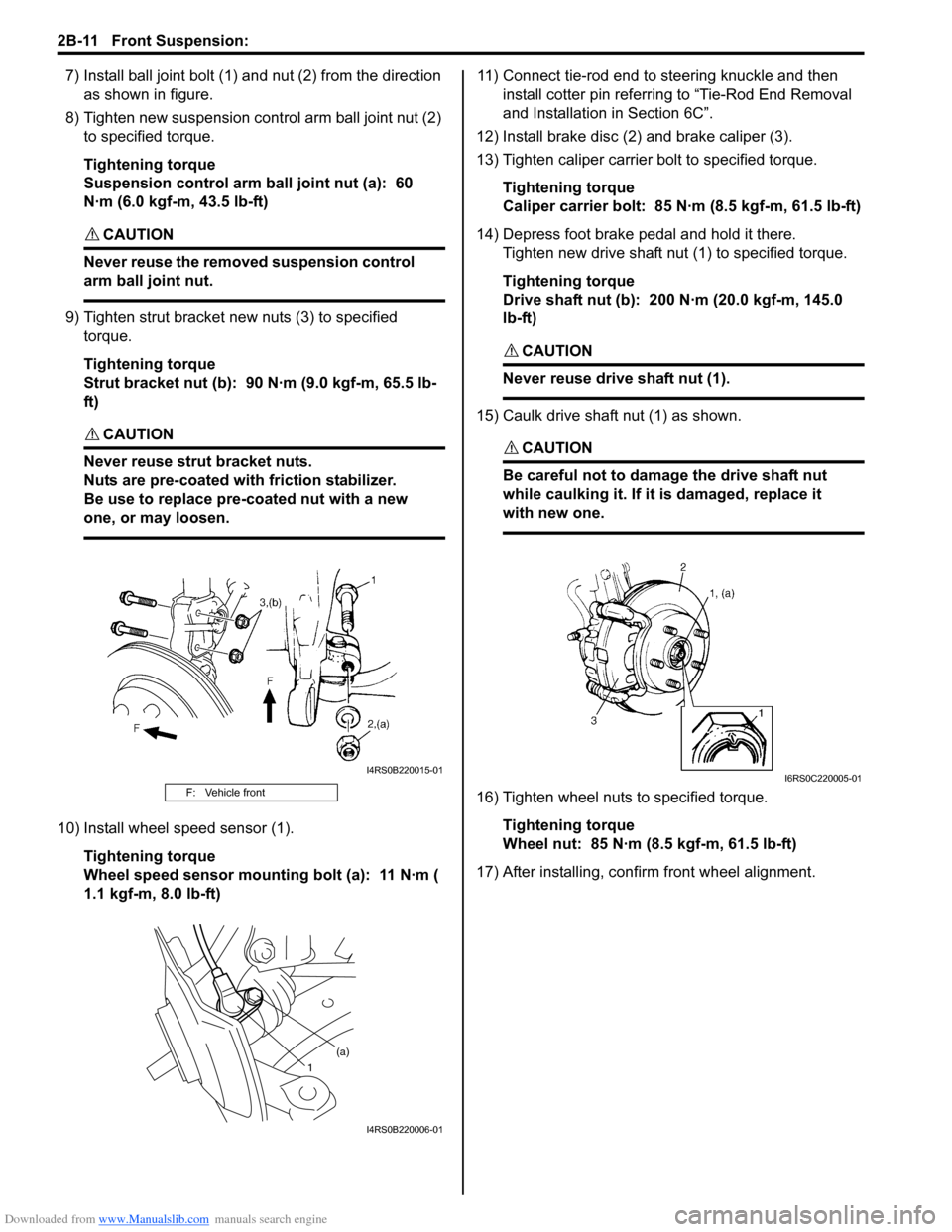
7) Install ball joint bolt (1) and nut (2) from the direction
as shown in figure.
8) Tighten new suspension co ntrol arm ball joint nut (2)
to specified torque.
Tightening torque
Suspension control arm ball joint nut (a): 60
N·m (6.0 kgf-m, 43.5 lb-ft)
CAUTION!
Never reuse the removed suspension control
arm ball joint nut.
9) Tighten strut bracket new nuts (3) to specified torque.
Tightening torque
Strut bracket nut (b): 90 N·m (9.0 kgf-m, 65.5 lb-
ft)
CAUTION!
Never reuse strut bracket nuts.
Nuts are pre-coated with friction stabilizer.
Be use to replace pre-coated nut with a new
one, or may loosen.
10) Install wheel speed sensor (1).
Tightening torque
Wheel speed sensor mounting bolt (a): 11 N·m (
1.1 kgf-m, 8.0 lb-ft) 11) Connect tie-rod end to steering knuckle and then
install cotter pin referrin g to “Tie-Rod End Removal
and Installation in Section 6C”.
12) Install brake disc (2) and brake caliper (3).
13) Tighten caliper carrier bolt to specified torque.
Tightening torque
Caliper carrier bolt: 85 N·m (8.5 kgf-m, 61.5 lb-ft)
14) Depress foot brake pedal and hold it there. Tighten new drive shaft nut (1) to specified torque.
Tightening torque
Drive shaft nut (b): 200 N·m (20.0 kgf-m, 145.0
lb-ft)
CAUTION!
Never reuse drive shaft nut (1).
15) Caulk drive shaft nut (1) as shown.
CAUTION!
Be careful not to damage the drive shaft nut
while caulking it. If it is damaged, replace it
with new one.
16) Tighten wheel nuts to specified torque.
Tightening torque
Wheel nut: 85 N·m (8.5 kgf-m, 61.5 lb-ft)
17) After installing, confirm front wheel alignment.F: Vehicle front
I4RS0B220015-01
1 (a)
I4RS0B220006-01
I6RS0C220005-01
Page 453 of 1496

Downloaded from www.Manualslib.com manuals search engine Front Suspension: 2B-20
Specifications
Tightening Torque SpecificationsS7RS0B2207001
NOTE
The specified tightening torque is also described in the following.
“Front Suspension Construction”
“Front Strut Assembly Components”
“Front Wheel Hub and Steering Knuckle Components”
“Front Suspension Frame, Stabilizer Bar and/or Bushings Components”
Reference:
For the tightening torque of fastener not specified in this section, refer to “Fasteners Information in Section 0A”.
Fastening part
Tightening torque
Note
N ⋅mkgf-mlb-ft
Tie-rod end lock nut 454.5 32.5 �)
Strut bracket nut 909.0 65.5 �) / �)
Brake hose mounting bolt 252.5 18.0 �)
Stabilizer joint nut 505.0 36.5 �) / �)
Strut nut 505.0 36.5 �)
Wheel nut 858.5 61.5 �) / �) / �)
Strut support lower nut 505.0 36.5 �)
Suspension control arm ball joint nut 606.0 43.5 �) / �)
Wheel speed sensor mounting bolt 111.1 8.0 �)
Caliper carrier bolt 858.5 61.5 �)
Drive shaft nut 200 20.0 145.0�)
Suspension control arm front bolt 959.5 68.0 �)
Suspension control arm rear bolt 959.5 68.0 �)
Stabilizer bar mounting bracket bolt 232.3 17.0 �)
Steering gear case mounting No.1 bolt 555.5 40.0 �)
Steering gear case mounting No.2 bolt 555.5 40.0 �)
Front suspension frame mounting bolt 150 15.0 108.5�)
Engine rear mounting bolt 555.5 40.0 �)
Steering shaft joint bolt 252.5 18.5 �)
Wheel bolt 858.5 61.5 �)
Page 482 of 1496
Downloaded from www.Manualslib.com manuals search engine 3A-4 Drive Shaft / Axle:
Front Drive Shaft Assembly On-Vehicle
Inspection
S7RS0B3106002
• Check boots for breakage or deterioration.
• Check wheel side joint for rattle or smooth rotation.
• Check differential side (or center shaft side) joint for smooth rotation.
If any abnormality is found, replace.
Front Drive Shaft Assembly Removal and
Installation
S7RS0B3106003
Removal
1) Hoist vehicle and remove wheel.
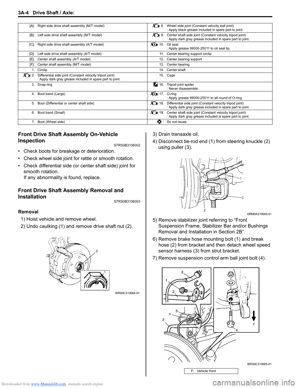
2) Undo caulking (1) and remove drive shaft nut (2). 3) Drain transaxle oil.
4) Disconnect tie-rod end (1) from steering knuckle (2)
using puller (3).
5) Remove stabilizer join t referring to “Front
Suspension Frame, Stabiliz er Bar and/or Bushings
Removal and Installati on in Section 2B”.
6) Remove brake hose mounting bolt (1) and break hose (2) from bracket and then detach wheel speed
sensor harness (3) from strut bracket.
7) Remove suspension contro l arm ball joint bolt (4).
[A]: Right side drive shaft assembly (M/T model) 8. Wheel side joint (Constant velocity ball joint)
: Apply black grease included in spare part to joint.
[B]: Left side drive shaft assembly (M/T model) 9. Center shaft side joint (Constant velocity tripod joint)
: Apply dark gray grease included in spare part to joint.
[C]: Right side drive shaft assembly (A/T model) 10. Oil seal
: Apply grease 99000-25011 to oil seal lip.
[D]: Left side drive shaft assembly (A/T model) 11. Center bearing support circlip
[E]: Center shaft assembly (A/T model) 12. Center bearing support
[F]: Center shaft assembly (M/T model) 13. Center bearing
1. Circlip 14. Center shaft
2. Differential side joint (Constant velocity tripod joint) : Apply dark gray grease included in spare part to joint. 15. Cage
3. Snap ring 16. Tripod joint spider
: Never disassemble.
4. Boot band (Large) 17. O-ring
: Apply grease 99000-25011 to all round of O-ring.
5. Boot (Differential or center shaft side) 18. Differential side joint (Constant velocity tripod joint)
: Apply dark gray grease included in spare part to joint.
6. Boot band (Small) 19. Center shaft side joint (Constant velocity tripod joint)
: Apply dark gray grease included is spare part to joint.
7. Boot (Wheel side) : Do not reuse.
I6RS0C310004-01
F: Vehicle front
I3RM0A310003-01
I6RS0C310005-01
Page 496 of 1496

Downloaded from www.Manualslib.com manuals search engine 4-ii Table of Contents
Repair Instructions ..............................................4D-2Parking Brake Inspection and Adjustment ..........4D-2
Parking Brake Cable Removal and Installation ......................................................... 4D-3
Parking Brake Lever Removal and Installation ....4D-3
Specifications .... ...................................................4D-4
Tightening Torque Specifications ........................4D-4
ABS ........................................... .................4E-1
Precautions........................................................... 4E-1
Precautions in Diagnosing Troubles ................... 4E-1
Precautions in On-Vehicle Service...................... 4E-1
Precautions in Hydraulic Unit Operation Check ................................................................ 4E-1
General Description ............................................. 4E-2 ABS Description .................................................. 4E-2
ABS Hydraulic Unit / Control Module Assembly Description ....................................... 4E-2
CAN Communication System Description........... 4E-3
Schematic and Routing Diagram ........................ 4E-4 ABS Schematic ................................................... 4E-4
ABS Wiring Circuit Diagram ................................ 4E-5
Component Location ........... ................................ 4E-7
ABS Components Location ................................. 4E-7
Front Wheel Speed Sensor Components Location ............................................................ 4E-7
Rear Wheel Speed Sensor Components Location ............................................................ 4E-8
Diagnostic Information and Procedures ............ 4E-8 ABS Check .......................................................... 4E-8
ABS Warning Light Check................................. 4E-10
EBD Warning Light (Brake Warning Light) Check .............................................................. 4E-10
DTC Check........................................................ 4E-11
DTC Table ......................................................... 4E-11
DTC Clearance ................................................. 4E-12
Scan Tool Data ................................................. 4E-12
ABS Warning Light Does Not Come ON at Ignition Switch ON .......................................... 4E-13
ABS Warning Light Comes ON Steady ............. 4E-14
EBD Warning Light (Brake Warning Light) Comes ON Steady .......................................... 4E-15
Serial Data Link Circuit Check .......................... 4E-16
DTC C1021, C1022 / C1025, C1026 / C1031, C1032 / C1035, C1036: Right-Front / Left-
Front / Right-Rear / Left-Rear Wheel Speed
Sensor Circuit or Sensor Ring ........................ 4E-18
DTC C1041 / C1045 / C1051 / C1055, DTC C1042 / C1046 / C1052 / C1056: Right-Front
/ Left-Front / Right-Rear / Left-Rear Inlet
Solenoid Circuit, Right-Front / Left-Front /
Right-Rear / Left-Rear Outlet Solenoid
Circuit .............................................................. 4E-20
DTC C1057: Power Source Circuit ................... 4E-21
DTC C1061: ABS Pump Motor and/or Motor Driver Circuit ................................................... 4E-22
DTC C1063: Solenoid Valve Power Supply Driver Circuit ................................................... 4E-23
DTC C1071: ABS Control Module..................... 4E-24 DTC U1073: Control Module Communication
Bus Off ............................................................ 4E-25
DTC U1100: Lost Communication with ECM (Reception Error)............................................. 4E-27
Repair Instructions ............ ................................ 4E-28
ABS Hydraulic Unit Operati on Check................ 4E-28
ABS Hydraulic Unit / Control Module
Assembly Components ...... ............................. 4E-29
ABS Hydraulic Unit / Control Module
Assembly On-Vehicle Inspection .................... 4E-29
ABS Hydraulic Unit / Control Module
Assembly Removal and Inst allation ................ 4E-29
Front / Rear Wheel Speed Sensor On-Vehicle Inspection ........................................................ 4E-31
Front Wheel Speed Sensor Removal and Installation ....................................................... 4E-32
Front Wheel Speed Sensor Inspection ............. 4E-32
Rear Wheel Speed Sensor Removal and Installation ....................................................... 4E-33
Rear Wheel Speed Sensor Inspection .............. 4E-34
Front Wheel Encoder On-Veh icle Inspection .... 4E-34
Front wheel Enco der Removal and
Installation ....................................................... 4E-34
Rear Wheel Encoder On-Veh icle Inspection..... 4E-34
Rear Wheel Encoder Removal and Installation ....................................................... 4E-34
Specifications ..................... ................................ 4E-35
Tightening Torque Specifications ...................... 4E-35
Special Tools and Equipmen t ........................... 4E-35
Special Tool ...................................................... 4E-35
Electronic Stability Prog ram ...................4F-1
Precautions ........................................................... 4F-1
Precautions in Diagnosing Troubles ................... 4F-1
Precautions in On-Vehicle Service...................... 4F-1
Precautions in Hydraulic Unit Operation Check ................................................................ 4F-1
Precautions in Sensor Calibration ....................... 4F-1
Precautions in Speedometer Test or Other Tests ................................................................. 4F-2
General Description ............................................. 4F-2 Electronic Stability Program Description ............. 4F-2
Electronic Stability Program Construction ........... 4F-3
ESP® Hydraulic Unit / Control Module
Assembly Description........................................ 4F-5
Warning Lamp, Indicator Lamp Description ........ 4F-6
CAN Communication System Description........... 4F-6
CAN Communication System For Electronic Stability Program Description ............................ 4F-7
Schematic and Routing Diagram ........................ 4F-8 Electronic Stability Program Schematic .............. 4F-8
Electronic Stability Program Wiring Circuit Diagram............................................................. 4F-9
Component Location ............ ............................. 4F-11
Electronic Stability Program Component
Location........................................................... 4F-11
Diagnostic Information and Procedures .......... 4F-12 Electronic Stability Program System Check ...... 4F-12
ESP® Warning lamp Check .............................. 4F-14