2008 SUZUKI GRAND VITARA door lock
[x] Cancel search: door lockPage 27 of 290

2-14
BEFORE DRIVING
66J22-03E
Ta i l g a t eIf you can not unlock the tailgate due to a
discharged battery or malfunction, follow
the procedures below to unlock the tailgate
from inside the vehicle.
1) Remove the luggage compartment
cover.
2) Fold the rear seat forward for easier
access. Refer to the “Folding Rear
Seats” section for details on how to fold
the rear seat forward.
64J202
3) Remove the cap (1) by hand.
4) Break the vinyl using a jack handle or a
flat blade screw driver to access the
emergency lever (2).
64J203
5) Push down on the emergency lever (2)
using a jack handle or a flat blade screw
driver. To lock the tailgate, push up on
the emergency lever (2).
After using the emergency lever, be sure to
see your SUZUKI dealer.
WindowsPower Window Controls
(if equipped)Driver’s side
64J011
The power windows can only be operated
when the ignition switch is in the “ON” posi-
tion.
The driver’s door has switches (1), (2), (4),
(5), to operate the driver’s window, the
front passenger’s window, the rear left win-
dow and right window, respectively.
(1)
WARNING
To avoid injury, do not use your fin-
ger to push the emergency lever.
(2)
(1)
(2) (4)
(5)
Windows: 3, 8
Page 28 of 290
2-15BEFORE DRIVING
66J22-03E
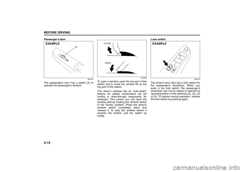
Passenger’s door
66J164
The passenger’s door has a switch (3) to
operate the passenger’s window.
81A009
To open a window, push the top part of the
switch and to close the window lift up the
top part of the switch.
The driver’s window has an “auto-down”
feature for added convenience (at toll
booths or drive-through restaurants, for
example). This means you can open the
window without holding the window switch
in the “Down” position. Press the driver’s
window switch completely down and
release it. To stop the window before it
reaches the bottom, pull the switch up
briefly.Lock switch
64J013
The driver’s door also has a lock switch for
the passenger’s window(s). When you
push in the lock switch, the passenger’s
window(s) can not be raised or lowered by
operating either of the switches (2), (3), (4)
or (5). To restore normal operation, release
the lock switch by pushing again.
(3)
EXAMPLE
CLOSE
OPEN
EXAMPLE
Windows: 3, 8
Mirrors: 3, 8
Page 59 of 290

2-46
BEFORE DRIVING
66J22-03E
Note that even though your vehicle may be
moderately damaged in a collision, the col-
lision may not have been severe enough to
trigger the front, side, or side curtain air
bags to inflate. If your car sustains ANY
front-end or side damage, have the air bag
system inspected by an authorized
SUZUKI dealer to ensure it is in proper
working order.
Your vehicle is equipped with a diagnostic
module which records information about
the air bag system if the air bags deploy in
a crash. The module records information
about overall system status, which sensors
activated the deployment, and whether the
front seat belts were in use.
Servicing the Air Bag SystemIf the air bags inflate, have the air bags and
related components replaced by an autho-
rized SUZUKI dealer as soon as possible.
If your vehicle ever gets in deep water and
the driver’s floor is submerged, the air bag
controller could be damaged. If this hap-
pens, have the air bag system inspected
by the SUZUKI dealer as soon as possible.
Special procedures are required for servic-
ing or replacing an air bag. For that reason,
only an authorized SUZUKI dealer should
be allowed to service or replace your air
bags. Please remind anyone who services
your SUZUKI that it has air bags.
Service on or around air bag components
or wiring must be performed only by an
authorized SUZUKI dealer. Improper ser-
vice could result in unintended air bag
deployment or could render the air bags
inoperative. Either of these two conditions
may result in severe injury.
To prevent damage or unintended inflation
of the air bag system, be sure the battery
is disconnected and the ignition switch has
been in the “LOCK” position for at least 90
seconds before performing any electrical
service work on your SUZUKI. Do not
touch air bag system components or wires.
The wires are wrapped with yellow tape or
yellow tubing, and the couplers are yellow
for easy identification.Scrapping a car that has an undeployed air
bag can be hazardous. Ask your dealer,
body repair shop or scrap yard for help
with disposal.
If it is necessary to modify the advanced
front air bag system to accommodate a
person with disabilities, owners in the con-
tinental United States can call American
Suzuki toll-free at 1-800-934-0934, or write
to:
American Suzuki Motor Corporation
Automotive Customer Relations
3251 East Imperial Highway
Brea, CA 92821-6795
If you purchased your SUZUKI in Canada
please contact the Suzuki Canada Cus-
tomer Relations Department by telephone
at 1-905-889-2677 extension 2254 or in
writing at:
Suzuki Canada Inc.
Customer Relations
100 East Beaver Creek Road
Richmond Hill, On
L4B 1J6
WARNING
(Continued)
For vehicles with side air bags, do
not place seat covers on the front
seats, because seat covers could
restrict the air bag’s inflation. Also,
do not place any cup holders or
other objects on the door, as these
objects could be propelled by the
air bag in the event of a crash.
Either of these conditions may
cause severe injury.
Page 63 of 290

3-2
STEERING COLUMN CONTROLS
66J22-03E
ACC
Accessories such as the radio can oper-
ate, but the engine is off.
ON
This is the normal operating position. All
electrical systems are on.
START
This is the position for starting the engine
using the starter motor. The key should be
released from this position as soon as the
engine starts.
Ignition key reminder (if equipped)
A buzzer sounds intermittently to remind
you to remove the ignition key if it is in the
ignition switch when the driver’s door is
opened.
Vehicle With Keyless Start System
63J270
The ignition switch can be operated with-
out using an ignition key when the remote
controller is in an area of the vehicle other
than the rear luggage area. To turn the
ignition switch, first push in the switch.
NOTE:
You must push in the ignition switch to turn
it from the “LOCK” position to the “ACC”
position. To return to the “LOCK” position
from the “ACC” position, turn the ignition
switch counterclockwise while pushing in
the switch.
66J022
If the keyless start system blue indicator
light illuminates on the instrument cluster,
you can turn the ignition switch. If the red
indicator light illuminates, you can not turn
the ignition switch.
NOTE:
The ignition switch can be turned to the
“ACC” position when the keyless start
system blue indicator light illuminates.
The blue indicator light will illuminate for
several seconds when you push in the
ignition switch and then will turn off to
protect the system. In this case, you
must release the ignition switch and
push it in again to illuminate the blue
indicator light.
If the keyless start system red indicator
light illuminates, the remote controller
may not be in the vehicle or the battery
(1)(2)(3)
(4)
EXAMPLE
Ignition Switch: 8, 10
Page 64 of 290

3-3STEERING COLUMN CONTROLS
66J22-03E
of the remote controller may be unreli-
able.
NOTE:
If the battery of the remote controller
runs down or there are strong radio
waves or noise, the operating range may
be narrower or the remote controller may
be inoperative.
If the remote controller is too close to the
door glass, it may not operate.
The ignition switch may not turn when
the remote controller is on the instru-
ment panel, in the glove box, in the door
pocket, in the sun visor or on the floor.
You can also turn the ignition switch by
inserting the ignition key into the slot.The ignition switch has the following four
positions:
LOCK (1)
This is the normal parking position. It is the
only position in which the key can be
removed. It locks the ignition, and prevents
normal use of the steering wheel.
For vehicles with an automatic transmis-
sion, the gearshift lever must be in the “P”
(Park) position to turn the key to the
“LOCK” position.
To release the steering lock, turn the igni-
tion switch clockwise to one of the other
positions. If you have trouble turning the
ignition switch to unlock the steering, try
turning the steering wheel slightly to the
right or left while turning the switch.
NOTE:
You must push the ignition switch in to turn
it to the “ACC” position. Also you must
push the ignition switch in to return it to the
“LOCK” position.
ACC (2)
Accessories such as the radio can oper-
ate, but the engine is off.
ON (3)
This is the normal operating position. All
electrical systems are on.START (4)
This is the position for starting the engine
using the starter motor. The switch should
be released from this position as soon as
the engine starts.
Ignition switch reminder
(When using the keyless start system)
A buzzer sounds intermittently to remind
you to return the ignition switch to the
“LOCK” position if it is in the “ACC” position
when the driver’s door is opened.
Ignition key reminder
(When using the ignition key)
A buzzer sounds intermittently to remind
you to remove the ignition key if it is in the
ignition switch when the driver’s door is
opened.
CAUTION
The remote controller is a sensitive
electronic instrument. To avoid dam-
aging the remote controller:
Do not expose it to impacts, mois-
ture or high temperature such as by
leaving it on the dashboard under
direct sunlight.
Keep the remote controller away
from magnetic objects such as a
television.
Ignition Switch: 8, 10
Page 134 of 290

5-3OTHER CONTROLS AND EQUIPMENT
66J22-03E
Your vehicle is equipped with either a
manual transmission or automatic trans-
mission. The gearshift lever for each trans-
mission type is shown in the illustrations.
For details on how to use the transmission,
refer to the “Using the Transmission” in
“OPERATING YOUR VEHICLE” section.
Fuel Filler Cap
64J085
64J253
The fuel filler cap is located on the right
rear side of the vehicle. The fuel filler door
can be unlocked by pulling up on the
opener lever located on the outboard sideof the driver’s seat and can be locked by
simply closing the door.
60G069
To remove the fuel filler cap:
1) Open the fuel filler door.
2) Remove the cap by turning it counter-
clockwise.
To reinstall the fuel filler cap:
1) Turn the cap clockwise until you hear
several clicks.
2) Close the fuel filler door.
EXAMPLE
WARNING
Remove the fuel filler cap slowly. The
fuel may be under pressure and may
spray out, causing injury.Open Close
Gearshift Lever: 10
Fuel Filler Cap: 5
Page 155 of 290

5-24
OTHER CONTROLS AND EQUIPMENT
66J22-03E
You can use the roof rails or the roof rack
anchors to attach the optional roof rack
which is available at your SUZUKI dealer.
If you use a roof rack, observe the instruc-
tions and precautions in this section and
provided with the roof rack.
(For vehicles with roof rack anchors)
To remove the cap, slide the cap in the
direction of the arrow (1) and then lift the
edge of the cap up as shown in the illustra-
tion. To install the cap, put in the front part
of the cap, slide the cap in the opposite
direction of the arrow (1) and then push
down the rear part of the cap.
Make sure the roof rack is securely
installed.
To mount various types of cargo (such
as skis, bicycles, etc.) properly, use suit-
able attachments which are available
from your SUZUKI dealer. Be sure to
install the attachments properly and
securely according to the instructions
provided. Do not mount cargo directly on
the roof panel. The cargo can damage
the roof panel.
The gross weight of the roof rack plus
cargo must not exceed the loading
capacity (75 kg (165 lbs)). Also, do not
let the gross vehicle weight (fully loaded
vehicle including driver, passengers,
cargo, roof load and trailer tongue
weight) exceed the Gross Vehicle
Weight Rating (GVWR) listed on the
driver’s door lock pillar. Mount and secure the cargo onto the
roof rack properly according to the
instructions provided. Be sure to stow
the heaviest items at the bottom and dis-
tribute the cargo as evenly as possible.
Do not carry items so large that they
hang over the bumpers or the sides of
the vehicle, or block your view.
Secure the front and rear ends of long
items – such as wood panels, surfboards
and so forth – to both the front and rear
of the vehicle. You should protect the
painted surfaces of the vehicle from
scuffing caused by tie-down ropes.
Check periodically to make sure the roof
rack is securely installed and free from
damage.
For vehicles with roof rack anchors,
make sure the anchors are covered with
the caps when not in use.
WARNING
Abrupt maneuvers or failure to
properly secure cargo can allow
the cargo to fly off the vehicle and
hit others, causing personal injury
or property damage.
Mount cargo securely and avoid
abrupt maneuvers such as “jack-
rabbit” starts, sharp turns, fast cor-
nering and sudden braking. Check
periodically to make sure that
cargo is securely fastened.
Large, bulky, long, or flat items can
affect vehicle aerodynamics or be
caught by the wind, and can reduce
vehicle control resulting in an acci-
dent and personal injury. Drive
cautiously at reduced speed when
carrying this type of cargo.
HomeLink:
Page 156 of 290

5-25OTHER CONTROLS AND EQUIPMENT
66J22-03E
HomeLink
® (if equipped)
66J092
HomeLink
® and the HomeLink
® house are
registered trademarks of Johnson
Controls, Inc.
The HomeLink
® Wireless Control System
provides a convenient way to replace up to
three hand-held radio-frequency (RF)
transmitters used to activate devices such
as gate operators, garage door openers,
entry door locks, security systems, even
home lighting. Additional HomeLink
® infor-
mation can be found on the Internet at
www.homelink.com
or by calling 1-800-
355-3515.
Before programming HomeLink
® to a
garage door opener or gate operator,
make sure that people and objects are out
of the way of the device to prevent poten-
tial harm or damage. When programming a
garage door opener, it is advised to park
outside of the garage. Do not use
HomeLink
® with any garage door opener
that lacks safety stop and reverse features
as required by U.S. federal safety stan-dards (this includes any garage door
opener model manufactured before April 1,
1982). A garage door that cannot detect an
object – signaling the door to stop and
reverse – does not meet current U.S. fed-
eral safety standards. For more informa-
tion, contact HomeLink
® at
www.homelink.com
or by calling 1-800-
355-3515.
Retain the original transmitter of the RF
device you are programming for use in
other vehicles as well as for future
HomeLink
® programming. It is also sug-
gested that upon the sale of the vehicle,
the programmed HomeLink
® buttons be
erased for security purposes. Refer to
“Programming HomeLink
®” (step 1) only)
or, for assistance, contact HomeLink
® at
www.homelink.com
or by calling 1-800-
355-3515.
Programming HomeLink
®
NOTE:
Some vehicles may require the ignition
switch to be turned to the second (or
“accessories”) position or the “on” position
for programming and/or operation of
HomeLink
®. It is also recommended that a
new battery be placed in the hand-held
transmitter of the device being pro-
grammed to HomeLink
® for quicker train-
ing and accurate transmission of the radio-
frequency signal. Do not repeat “Program-
ming HomeLink
®” – step 1) to train addi-
tional devices to a second or thirdHomeLink
® button. Begin with “Program-
ming HomeLink
®” – step 2).
66J050
1) Press and hold the two outer
HomeLink
® buttons (buttons one and
three) – releasing only when the indica-
tor light begins to flash (after 20 sec-
onds). Do not hold the buttons for
longer than 30 seconds and do not
repeat step 1) to program a second
and/or third hand-held transmitter to the
remaining two HomeLink
® buttons.
2) Position the end of your hand-held
transmitter 5–14 cm (1–3 inches) away
from the HomeLink
® button you wish to
program while keeping the indicator
light in view.
3) Simultaneously press and hold both the
chosen HomeLink® and hand-held
transmitter buttons. Do not release the
buttons until step 4) has been com-
pleted.
HomeLink: