2008 SUZUKI GRAND VITARA door lock
[x] Cancel search: door lockPage 158 of 290

5-27OTHER CONTROLS AND EQUIPMENT
66J22-03E
Gate Operator / Canadian Program-
mingCanadian radio-frequency laws require
transmitter signals to “time-out” (or quit)
after several seconds of transmission –
which may not be long enough for
HomeLink
® to pick up the signal during
programming. Similar to this Canadian law,
some U.S. gate operators are designed to
“time-out” in the same manner.
If you live in Canada or you are having dif-
ficulties programming a gate operator by
using the Programming procedures
(regardless of where you live), replace
“Programming HomeLink
®” step 3) with
the following:
NOTE:
If programming a garage door opener or
gate operator, it is advised to unplug the
device during the “cycling” process to pre-
vent possible overheating.
3) Continue to press and hold the
HomeLink
® button while you press and
release – every two seconds (“cycle”)
your hand-held transmitter until the fre-
quency signal has successfully been
accepted by HomeLink
®. (The indicator
light will flash slowly and then rapidly.)
Proceed with “Programming HomeLink
®”
step 4) to complete.
Using HomeLink
®
To operate, simply press and release the
programmed HomeLink
® button. Activation
will now occur for the trained device (i.e.
garage door opener, gate operator, secu-
rity system, entry door lock, home/office
lighting, etc.). For convenience, the hand-
held transmitter of the device may also be
used at any time. In the event that there
are still programming difficulties or ques-
tions, contact HomeLink
® at
www.homelink.com
or 1-800-355-3515.
Erasing HomeLink
® Buttons
To erase programming from the three but-
tons (individual buttons cannot be erased
but can be “reprogrammed” as outlined
below), follow the step noted:
Press and hold the two outer HomeLink
®
buttons until the indicator light begins to
flash-after 20 seconds. Release both but-
tons. Do not hold for longer that 30 sec-
onds. HomeLink
® is now in the train (or
learning) mode and can be programmed at
any time beginning with “Programming
HomeLink
®” – step 2).
Reprogramming a Single
HomeLink
® Button
To program a device to HomeLink
® using a
HomeLink
® button previously trained, fol-
low these steps:
1) Press and hold the desired HomeLink
®
button. DO NOT release the button.2) The indicator light will begin to flash
after 20 seconds. Without releasing the
HomeLink
® button, proceed with “Pro-
gramming HomeLink
®” – step 2).
For questions or comments, contact
HomeLink
® at www.homelink.com
or 1-
800-355-3515.
Page 161 of 290

6-2
OPERATING YOUR VEHICLE
66J22-03E
Daily Inspection ChecklistBefore Driving1) Make sure that windows, mirrors, lights
and reflectors are clean and unob-
structed.
2) Visually check the tires for the following
points:
– the depth of the tread groove
– abnormal wear, cracks and damage
– loose wheel nuts
– existence of foreign material such as
nails, stones, etc.
Refer to “Tires” in “INSPECTION AND
MAINTENANCE” section for details.
3) Look for fluid, oil leaks.
NOTE:
It is normal for water to drip from the air
conditioning system after use.
4) Make sure the hood is fully closed and
latched.
5) Check the headlights, turn signal lights,
brake lights and horn for proper opera-
tion.
6) Lock all doors.
7) Adjust the seat and adjustable head
restraints (if equipped).
8) Check the brake pedal and the parking
brake lever.
9) Adjust the mirrors.
10)Make sure that you and all passengers
have properly fastened your seat belts.11)Make sure that all warning lights come
on as the key is turned to the “ON” or
“START” position.
12)Check all gauges.
13)Make sure that the BRAKE SYSTEM
WARNING light turns off when the
parking brake is released.
Once a week, or each time you fill your fuel
tank, perform the following under-hood
checks:
1) Engine oil level
2) Coolant level
3) Brake fluid level
4) Power steering (if equipped) fluid level
5) Windshield washer fluid level
6) Hood latch operation
Pull the hood release handle inside the
vehicle. Make sure that you cannot
open the hood all the way without
releasing the secondary latch. Be sure
to close the hood securely after check-
ing for proper latch operation. See the
item “All Latches, Hinges and Locks” of
“CHASSIS AND BODY” in the “Periodic
Maintenance Schedule” in the
“INSPECTION AND MAINTENANCE”
section for lubrication schedule.
Starting the EngineBefore Starting the Engine1) Make sure the parking brake is set fully.
2) Manual Transmission – Shift into “N”
(Neutral) and depress the clutch pedal
all the way to the floor.
Hold it while starting the engine.
Automatic Transmission – If the gear-
shift lever is not in “P” (Park) position,
shift into “P”. (If you need to re-start the
engine while the vehicle is moving, shift
into “N”.)
NOTE:
The engine of manual transmission vehicle
will not start unless the clutch pedal is
depressed.
NOTE:
Automatic transmission vehicles have a
starter interlock device which is designed
to keep the starter from operating if the
transmission is in any of the drive posi-
tions.
WARNING
Make sure the hood is fully closed
and latched before driving. If it is not,
it can fly up unexpectedly during
driving, obstructing your view and
resulting in an accident.
WARNING
Make sure that the parking brake is
set fully and the transmission is in
Neutral (or Park for vehicles with an
automatic transmission) before
attempting to start the engine.
Daily Inspection Checklist: NO
Starting the Engine: 1
Page 163 of 290

6-4
OPERATING YOUR VEHICLE
66J22-03E
When the remote controller is in the vehi-
cle except the rear luggage area, you can
turn the ignition switch without using an
ignition key.
NOTE:
If the battery of the remote controller
runs down or there are strong radio
waves or noise, the operating range may
be narrower or the remote controller may
be inoperative.
If the remote controller is too close to the
door glass, it may not operate.
The ignition switch may not turn when
the remote controller is on the instru-
ment panel, in the glove box, in the door
pocket, in the sun visor or on the floor.
You can also turn the ignition switch by
inserting the ignition key into the slot.
Engine Block Heater
(if equipped)
65D420
The engine block heater will help you start
the engine more easily in very cold
weather (–18°C (0°F) or below). To use the
engine block heater:
1) Turn off the engine.
2) Open the engine hood.
3) Untie the block heater cord and remove
the block heater plug cap. When the
engine block heater is not in use,
ensure the heater cord is secured to
prevent contact with any moving parts.
4) Using a heavy-duty, three-prong
grounded extension cord, plug the
female end into the block heater socket
and the male end into a normal,
grounded 110-volt AC outlet.NOTE:
Activate the heater at least four hours
before you start the engine. However, as
the heating time varies depending on the
ambient temperature and other factors,
adjust the time by observing the engine
cranking condition.
After using the block heater:
1) Unplug the extension cord and reinstall
the plug cap.
2) Tie the block heater cord back to its
original position.
CAUTION
The remote controller is a sensitive
electronic instrument. To avoid dam-
aging it, do not expose it to impacts,
moisture or high temperature (such
as on the dashboard under direct
sunlight).
WARNING
To avoid serious personal injury
caused by electrical shock or fire:
Do not plug the cord into a non-
grounded outlet. Only use a prop-
erly grounded three-prong 110-volt
AC outlet.
Do not use a 2-wire (non-grounded)
extension cord.
Only use a heavy-duty, three-prong
extension cord rated for at least 15
amps.
CAUTION
Secure the block heater cord back to
its original position or to the routed
position. A loose cord could get
caught in the engine accessory drive
belt(s) or other moving parts.
Starting the Engine: 1
Engine Block Heater: 1
Page 193 of 290

7-6
DRIVING TIPS
66J22-03E
WARNING
In addition to following the driving
tips in this section, it is important to
observe the following precautions for
on-road and off-road driving.
Driver and passengers should wear
seat belts at all times.
Do not let anyone else drive your
vehicle unless they are also aware
of the vehicle characteristics and
handling differences described in
this section.
Avoid loaning your vehicle to any-
one unless you accompany them.
Make sure your tires are in good
condition and always maintain the
specified tire pressure. Refer to
“Tires” in the “INSPECTION AND
MAINTENANCE” section for
details.
Do not use tires other than those
specified by SUZUKI. Never use dif-
ferent sizes or types of tires on the
front and rear wheels. For informa-
tion regarding the specified tires,
refer to the Tire Inflation Pressure
Label located on the driver’s side
door pillar or the “SPECIFICA-
TIONS” section.
(Continued)
WARNING
(Continued)
Never use oversized tires or special
shocks and springs to raise (jack
up) your vehicle. This will raise the
center of gravity of the vehicle and
change its handling characteris-
tics. Oversized tires may also rub
against the fender over bumps,
causing vehicle damage or tire fail-
ure.
After driving through water, mud or
sandy ground, test the brakes while
driving at a slow speed to see if
they have maintained their normal
effectiveness. If the brakes are less
effective than normal, dry them by
repeatedly applying the brakes
while driving slowly until the
brakes have regained their normal
effectiveness.
Do not use “4H LOCK” or “4L
LOCK” drive for normal driving.
After extended operation in mud,
sand or water, have the brakes
inspected by your authorized
SUZUKI dealer as soon as possi-
ble.
Page 233 of 290

9-26
INSPECTION AND MAINTENANCE
66J22-03E
D. Construction Code
This letter code is used to indicate the
type of ply construction in the tire. The
letter “R” means radial ply tire con-
struction, the letter “D” means diago-
nal or bias ply construction, and the
letter “B” means belted-bias ply con-
struction.
E. Rim Diameter
This two-digit number is the wheel or
rim diameter in inches.
Tire Inflation PressureTire inflation pressure should be checked
when the tire is cold. “Cold tire inflation
pressure” is the pressure in a tire that has
been driven less than 1 mile (1.6 km) or
has been standing for three hours or more.
54G307
The front, rear and spare tire pressure
specifications for your vehicle are shown
below and are listed on the Tire and Load-
ing Information Label, which is located on
the driver’s door lock pillar. The Tire and
Loading Information Label contains the fol-
lowing information:
Seating Capacity
Maximum Allowed Combined Weight of
Occupants and Cargo
Original Tire Size
Recommended Cold Tire Inflation Pres-
sure of Original TiresNOTE:
The tire inflation pressure will change due
to changes in atmospheric pressure, tem-
perature or tire temperature when driving.
To reduce the chance that the low tire
pressure warning light will come on due to
normal changes in temperature and atmo-
spheric pressure, it is important to check
and adjust the tire pressures when the
tires are cold. Tires that appear to be at the
specified pressure when checked after
driving, when the tires are warm, could
have pressure below the specification
when the tires cool down. Also, tires that
are inflated to the specified pressure in a
warm garage may have pressure below the
specification when the vehicle is driven
outside in very cold temperature. If you
adjust the tire pressure in a garage that is
warmer than the outside temperature, you
should add 1 psi to the recommended cold
tire inflation pressure for every 10°F differ-
ence between garage temperature and
outside temperature.
WARNING
Your SUZUKI is equipped with tires
which are all the same type and size.
This is important to ensure proper
steering and handling of the vehicle.
Never mix tires of different size or
type on the four wheels of your vehi-
cle. Mixing tires could cause you to
lose control while driving which may
lead to an accident. The size and type
of tires used should be only those
approved by SUZUKI Motor Corpora-
tion as standard or optional equip-
ment for your vehicle.
Recommended Cold Tire Inflation
Pressures
Front Tires220 kPa
32 psi
Rear Tires220 kPa
32 psi
Spare220 kPa
32 psi
Tires: 6
Page 244 of 290

9-37INSPECTION AND MAINTENANCE
66J22-03E
Fuse under the Dash BoardFuse box
64J192
64J158
PRIMARY
FUSEINDIVIDUAL FUSE
60A LAMP Head light, Accessory,
Dome light, Sunroof,
Hazard light, Door lock,
Rear fog light, Stop
lamp, Tail light
50A IGN 2 Wiper/Washer, Power
window, Seat heater
40A 4WD 4WD actuator
30A RDTR 1 Radiator fan
30A RDTR 2 Radiator fan
WARNING
If a fuse in the main fuse box blows,
be sure to have your vehicle
inspected by an authorized SUZUKI
dealer. Always use a genuine SUZUKI
replacement. Never use a substitute
such as a wire even for a temporary
fix, or extensive electrical damage
and a fire can result.
SPARE SPARE SPARE
SPARE
USE THE DESIGNATED
FUSES AND RELAYS ONLYSPARE SPARE
(A)
(B)
(C)
(D)
(E)
(F)
(G)
(H)(I)
(J)
(L)
(M)
(N)
(O)
(P)
(Q)
(R)
(S)
(T)
(U)
(K)(V)
(W)
(A) 15A STOP Stop lamp fuse
(B) – – Blank
(C) 15A ACC 3Accessory socket
fuse
(D) 10A CRUISE Cruise control fuse
(E) 15A ACC 2Cigar or Accessory
socket fuse
(F) 20A WIP Wiper fuse
(G) 15A IG2 SIGIgnition signal & Seat
heater fuse
(H) 10A BACK Back lamp fuse
(I) 10A ABS/ESPABS or ESP control-
ler fuse
(J) 15A A/B Air bag fuse
(K) – – Blank
(L) 15A HAZ Hazard light fuse
(M) 7.5A ST SIG Starter signal fuse
(N) 20ARR
BLOWBlank
(O) 25A S/R Sun roof motor fuse
(P) 15A DOME Dome lamp fuse
(Q) 10A TAIL Tail light fuse
(R) 20A D/LDoor lock actuator
fuse
(S) 15A ACCRadio, Remote door
mirror fuse
Bulb Replacement: 7
Page 249 of 290

9-42
INSPECTION AND MAINTENANCE
66J22-03E
Bulb
54G124
(3) Removal
(4) Installation
There are two types of bulb, “Full glass
type” (1) and “Glass/metal type” (2).
To remove and install a full glass type bulb
(1), simply pull out or push in the bulb.
To remove a glass metal type bulb (2) from
a bulb holder, push in the bulb and turn it
counterclockwise. To install a new bulb,
push it in and turn it clockwise.
You can access the individual bulb or bulb
holders as follows.Parking/Turn signal light
64J163
Trust this replacement job to your dealer as
the front grille and the headlight housing
must be removed for this job.
Rear combination light
64J164
License plate light
75F087
Door illumination light
64J165
(1)
(2) (3)
(4)EXAMPLE
EXAMPLE
Wiper Blades: 3
Page 271 of 290
12-2
GENERAL INFORMATION
66J22-03E
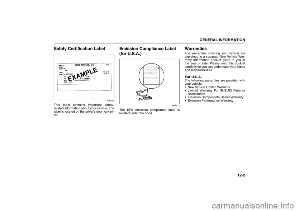
Safety Certification Label
52D059
This label contains important safety-
related information about your vehicle. The
label is located on the driver’s door lock pil-
lar.
Emission Compliance Label
(for U.S.A.)
60A412
The EPA emission compliance label is
located under the hood.
WarrantiesThe warranties covering your vehicle are
explained in a separate New Vehicle War-
ranty Information booklet given to you at
the time of sale. Please read this booklet
carefully so you can understand your rights
and responsibilities.For U.S.A.The following warranties are provided with
your vehicle:
New Vehicle Limited Warranty
Limited Warranty For SUZUKI Parts or
Accessories
Emission Components Defect Warranty
Emission Performance Warranty
Safety Certification Label: 6
Emission Compliance Label (For U.S.A.): 1, 2
Warranties: NO