Page 177 of 272
 Owners Manual Transporting children safely
178
Complete installation instructions are enclosed with the child safety seat.
WARNING
•The locking eyes have just been developed for child safety seats which
use the")
Transporting children safely
178
Complete installation instructions are enclosed with the child safety seat.
WARNING
•The locking eyes have just been developed for child safety seats which
use the “ISOFIX” system. You should therefore never attach other child
safety seats, seat belts or obje cts to the locking eyes - hazard!
•Ask a Škoda Service Partner whether a child seat which you bought for
another vehicle is recommended for use in a Škoda before using an “ISOFIX”
system.
•Certain child seats which use the “ISOFIX” system can be attached with
standard three-point seat belts. Please pay close attention to instructions
from the manufacturer of the child safety seat when installing and removing
the seat.
Note
•Child seats which use the “ISOFIX” system are currently available for children
weighing from 9 up to 18 kg. This correspo nds to an age range of from 9 months to
4 years.
•The child seats can also be fitted with the “Top Tether” system ⇒page 178.
Attaching child seat using the “Top Tether” system
IIn certain countries national legal provisions also require the equipment of the rear
seat with fixing eyes for child seat using the “Top Tether” system ⇒fig. 174 .
Always perform the installation and removal of the child seat using the “Top Tether”
system as stated in the instructions from the manufacturer of the child seat.
WARNING
•Attach the child seats with the “Top Tether” system only to the points
provided for this purpose ⇒fig. 174 .
•On no account should you equip your vehicle, e.g. mount screws or other
anchorage points.
•Pay attention to the important safety information regarding the use of
child seats.
Note
Store the remaining part of the belt for the “Top Tether” system in a textile pocket,
which is located at the child seat.
Fig. 174 Rear seat: Top
Te t h e r
NKO B6 20.book Page 178 Wednesday, March 26, 2008 3:15 PM
Page 178 of 272
 Owners Manual Intelligent Technology179
Using the systemSafetyDriving TipsGeneral MaintenanceBreakdown assistanceTechnical Data
Driving Tips
Intelligent Technology
Electronic stability programme (ESP)*
General
Gene")
Intelligent Technology179
Using the systemSafetyDriving TipsGeneral MaintenanceBreakdown assistanceTechnical Data
Driving Tips
Intelligent Technology
Electronic stability programme (ESP)*
General
General
The ESP aids you maintain control of your vehicle in situations in borderline driving
situations such as when negotiating a curve too fast. The risk of skidding is reduced
and your car thus offers greater driving stability depending on the conditions of the
road surface. This occurs at all speeds.
The following systems are integrated into the electronic stability programme:
•Electronic Differential Lock (EDL),
•Traction control system (TCS),
•Driver-steering recommendation,
•Antilock brake system (ABS),
•Brake Assist,
•Uphill-Start off-Assist. Operating principle
The ESP switches on automatically when the engine is started and then conducts a
self-test. The ESP control unit processes data from the individual systems. It also
processes additional measurement data which are supplied by highly sensitive
sensors: the rotational velocity of the vehi
cle about its vertical axis, the lateral accel-
eration of the vehicle, the brakin g pressure and the steering angle.
The direction which the driver wishes to ta ke is determined based on the steering
angle and the speed of the vehicle and is constantly compared with the actual
behaviour of the vehicle. If differences exis t, such as the car beginning to skid, the
ESP will automatically brake the appropriate wheel.
The car is stabilised again by the forces which take effect when the wheel is braked.
Intervention into the brake system takes place primarily on the outer front wheel of
a vehicle which tends to oversteer (tendency for the rear of the vehicle to break
away) while occurs this is on the inner re ar wheel of a vehicle which tends to under-
steer (tendency to shift out of the curve). This braking control cycle is accompanied
by noises.
The ESP operates in combination with the ABS ⇒page 183. If there is a fault in the
ABS system, the ESP also does not operate.
The ESP warning light ⇒page 32 lights up in the instrument cluster when there is a
fault on the ESP.
Switching off
You can switch the ESP off and on again as you wish, by pressing the button
⇒ fig. 175 . The ESP warning light ⇒page 32 lights up in the instrument cluster
when the ESP is switched off.
The ESP should normally always be switched on. It may be good practice in certain
exceptional cases, such as when you wish to have wheel slip, to switch off the
system.
Examples:
Fig. 175 ESP switch
NKO B6 20.book Page 179 Wednesday, March 26, 2008 3:15 PM
Page 179 of 272
 Owners Manual Intelligent Technology
180
•when driving with snow chains
•when driving in deep snow or on a loose surface
•when it is necessary to rock a ca r free when it has become stuck.
then you should swi")
Intelligent Technology
180
•when driving with snow chains
•when driving in deep snow or on a loose surface
•when it is necessary to rock a ca r free when it has become stuck.
then you should switch on the ESP again.
WARNING
It is also not possible for the ESP to overcome the physical limits of the
vehicle. Even if a vehicle fitted with ESP you should still always adapt your
style of driving to the condition of the road surface and the traffic situation.
This particularly applies when driving on slippery and wet roads. The
increased safety offered must not tempt you to take greater risks than other-
wise - risk of an accident!
Note
•All four wheels must be fitted with the same tyres in order to achieve problem-
free operation of the ESP. Differing rolling circumferences of the tyres can lead to an
undesirable reduction in the engine output.
•Changes to vehicle (e.g. on engine, on the brakes, on chassis or other assign-
ment of tyres and wheels) can influence the function of the ESP ⇒page 228,
“Accessories, changes and replacement of parts”.
Electronic Differential Lock (EDS)*
The electronic differential lock pr events an individual wheel from
slipping.
Models fitted with ESP are equipped with electronic differential lock (EDL).
General
The EDL makes it much easier, and sometimes at all possible, to start off, accelerate
and climb a steep hill when the conditio ns of the road surface are unfavourable. Operating principle
The EDL is activated automatically, that is without any action on the part of the
driver. It monitors the speeds of the driven wheels with the aid of the ABS sensors.
Should only
one drive wheel begin spinning on a slippery surface there will be an
appreciable difference in the speed of the driven wheels. The EDL function brakes
the slipping wheel and the differential transmits a greater driving force to the other
driven wheel. This control proces s is also accompanied by noises.
Overheating of the brakes
The EDL switches off automatically if unusually severe stresses exist in order to
avoid excessive heat generation in the disc brake on the wheel which is being
braked. The vehicle can continue to be driven and has the same characteristics as a
vehicle not fitted with EDL.
The EDL switches on again automatically as soon as the brake has cooled down.
WARNING
•Depress the accelerator carefully when accelerating on uniformly slip-
pery road surfaces, such as ice and sn ow. The driven wheels might still spin
despite the EDL and affect the stability of the vehicle - risk of an accident!
•You should always adapt your style of driving to the condition of road
surface and to the traffic situation even when your vehicle is fitted with EDL.
The increased safety offered must not tempt you to take greater risks than
otherwise - risk of an accident!
Note
•If the ABS or ESP warning light comes on, this may also indicate a fault in the
EDL. Please have the car inspected as s oon as possible by a specialist garage.
•Changes to vehicle (e.g. on engine, on the brakes, on chassis or other assign-
ment of tyres and wheels) can in fluence the function of the EDL ⇒page 228,
“Accessories, changes and replacement of parts”.
NKO B6 20.book Page 180 Wednesday, March 26, 2008 3:15 PM
Page 180 of 272
 Owners Manual Intelligent Technology181
Using the systemSafetyDriving TipsGeneral MaintenanceBreakdown assistanceTechnical Data
Traction control system (TCS)
The traction control system prevents the driven wheels")
Intelligent Technology181
Using the systemSafetyDriving TipsGeneral MaintenanceBreakdown assistanceTechnical Data
Traction control system (TCS)
The traction control system prevents the driven wheels from spinning
when accelerating.
General
The TCS makes it much easier, and sometimes at all possible, to start off, accelerate
and climb a steep hill when the conditio ns of the road surface are unfavourable.
Operating principle
The TCS switches on automatically when th e engine is started and then conducts a
self-test. The system monitors the speeds of the driven wheels with the aid of the
ABS sensors. If the wheels are spinning, the force transmitted to the road surface is
automatically adapted by redu cing the engine speed. This occurs at all speeds.
The TCS operates in combination with the ABS ⇒page 183. The TCS will not func-
tion if a fault exists in the ABS system.
The TCS warning light ⇒page 31 lights up in the instrument cluster when there is a
fault on the TCS.
Switching off
You can switch the TCS off and on again as you wish by pressing the button
⇒ fig. 176 . The TCS warning light ⇒page 31 lights up in the instrument cluster
when the TCS is switched off. The TCS should normally always be switched on. It may be good practice in certain
exceptional cases, such as when you wish
to have wheel slip, to switch off the
system.
Examples:
•when driving with snow chains
•when driving in deep snow or on a loose surface
•when it is necessary to rock a car free when it has become stuck.
then you should switch on the TCS again.
WARNING
You should always adjust your style of driving to the conditions of the road
surface and the traffic situation. The increased safety offered must not tempt
you to take greater risks than otherwise - risk of an accident!
Note
•All four wheels must be fitted with the same tyres in order to achieve problem-
free operation of the TCS. Differing rolling circumferences of the tyres can lead to
an undesirable reduction in the engine output.
•Changes to vehicle (e.g. on engine, on the brakes, on chassis or other assign-
ment of tyres and wheels) can in fluence the function of the TCS ⇒page 228,
“Accessories, changes and replacement of parts”.
Driver-steering recommendation*
The driver-steering recommendation is an additional function of the electronic
stability programme (ESP). This function indicates to the driver in critical situations
by means of slight steering wheel impulses the direction evaluated by the system,
in which the vehicle must be steered, so that it stabilizes. The driver-steering
recommendation is active when braking shar ply on different road surfaces and on
the right and left vehicle side.
Fig. 176 TCS switch
NKO B6 20.book Page 181 Wednesday, March 26, 2008 3:15 PM
Page 181 of 272
 Owners Manual Intelligent Technology
182
WARNING
Even with this additional function the vehicle cannot be steered automati-
cally! The driver is furthermore fully reponsible for the steering of the
vehicle!
Brake")
Intelligent Technology
182
WARNING
Even with this additional function the vehicle cannot be steered automati-
cally! The driver is furthermore fully reponsible for the steering of the
vehicle!
Brakes
What has a negative effect on braking efficiency?
Wear-and-tear
Wear-and-tear to the brake pads is greatly dependent on the operating conditions
of the vehicle and your style of driving. Particularly if you drive a great deal in towns
and over short distances or if you adopt a sporty style of driving, it may be neces-
sary to have the thickness of the brake pads inspected at a specialist garage
between the service inspections.
Wet roads or road salt
There may be a certain delay before the brakes take full effect under certain condi-
tions such as when driving through water, during heavy rain showers or after the
vehicle has been washed in an automatic vehicle wash, since the brake discs and
brake pads may be moist or even have a coating of ice on them in winter. You
should dry the brakes as soon as possib le (by applying and releasing the brakes
several times, if the road conditions and the traffic situation allows it).
There also may be a certain delay before the full braking efficiency is available when
driving on roads which have been treated wi th road salt if you have not used the
brakes for some considerable time beforeha nd. The layer of salt on the brake discs
and brake pads must first be rubb ed off when you apply the brakes.
Corrosion
Corrosion on the brake discs and dirt on th e bake pads occur if the vehicle has been
parked for a long period and if you do not make much use of the braking system.
We recommend cleaning the brake discs by firmly applying the brakes at a fairly
high speed if you do not make much use of the braking system or if surface corro-
sion is present ⇒. Faults in the brake surface
If you notice that the braking distance
has suddenly become longer and that the
brake pedal can be depressed further, it is possible that a brake circuit of the dual-
circuit brake system has failed. Drive, in such cases, to the nearest specialist garage
without delay in order to have the problem rectified. Drive at a reduced speed while
on your way to the dealer and adapt your style of driving to the higher brake pedal
pressure required.
Low brake fluid level
An insufficient level of brake fluid may result in problems in the brake system. The
level of the brake fluid is monitored electronically ⇒page 34, “Brake system ”.
WARNING
•Only apply the brakes for the purpos e of drying and cleaning the brake
discs if the traffic conditions permit this. Do not place any other road users
in jeopardy.
•When retrospectively mounting a front spoiler, solid wheel hubs etc. one
must ensure that the air supply to the front wheel brakes is not reduced
otherwise the braking sy stem could run too hot.
•Allow for the fact that new brake pads do not achieve their full braking
efficiency until approximately 200 kilo metres. New brake pads must be first
“run in” before they develop their optimal friction force. You can, however,
compensate for this slightly reduced braking force by increasing the pres-
sure on the brake pedal. This guidelin e also applies to any new brake pads
installed at a future date.
Caution
•Never allow the brakes to ru b by applying slight pressure if you do not wish to
brake the vehicle. This causes the brakes to overheat and can also result in a longer
braking distance and excessive wear.
•Before negotiating a steep downhill sect ion, please reduce your speed, shift
down into the next lower gear (manual ge arbox) or select a lower driving stage
(automatic gearbox). This enables you to make full use of the braking power of the
NKO B6 20.book Page 182 Wednesday, March 26, 2008 3:15 PM
Page 182 of 272
 Owners Manual Intelligent Technology183
Using the systemSafetyDriving TipsGeneral MaintenanceBreakdown assistanceTechnical Data
vehicle and reduces the strain on the brakes
. Any additional braking should be done")
Intelligent Technology183
Using the systemSafetyDriving TipsGeneral MaintenanceBreakdown assistanceTechnical Data
vehicle and reduces the strain on the brakes
. Any additional braking should be done
intermittently, no t continuously.
Note
The hazard warning light system is switched on automatically in case of an emer-
gency braking at speeds greater than 60 km /h. The hazard warning light system is
switched off automatically after accelerating or driving off again.
Brake booster
The brake booster boosts the pressure which you generate with the brake pedal.
The necessary pressure is only gene rated when the engine is running.
WARNING
•Never switch off the engine before the vehicle is stationary.
•The brake booster only operates when the engine is running. Greater
physical effort for braking is required when engine is switched off. Because
if you do not stop as normal, this can cause an accident and severe injuries.
Antilock brake system (ABS)
ABS prevents the wheels locking when braking.
General
The ABS contributes significan tly to enhancing the active safety of your vehicle.
Compared to a car not fitted with the ABS brake system, you are able to retain
optimal steering ability even during a fu ll brake application on a slippery road
surface because the wheels do not lock up.
You must not expect, however, that the br aking distance will be shorter under all
circumstances as a result of the ABS. Th e braking distance for example on gravel
and fresh snow, when you should anyway be driving slowly and cautiously, will be
longer. Operating principle
The brake pressure will be reduced on a wheel which is rotating at a speed which is
too low for the speed of the vehicle and tend
ing to lock. This control cycle is notice-
able from a pulsating movement of the brake pedal which is accompanied by
noises. This is consciously intended to provide the driver with the information that
the wheels are tending to lock (ABS control range). You must always keep the brake
pedal depressed to enable the ABS to optimally control the brake application in this
braking range. Never interrupt the application of the brakes!
WARNING
•The ABS can also not overcome the physic al limits of your vehicle. Please
do not forget this, particularly when driv ing on icy or wet road surfaces. If the
ABS is operating within the control ra nge, adapt your speed immediately to
the conditions of the road surface and the traffic situation. The increased
safety offered by the ABS must not tempt you to take greater risks than
otherwise - risk of an accident!
•The normal braking system is still fully functional if there is an ABS fault.
Visit a specialist garage as quickly as po ssible and adjust your style of driving
to take account of the ABS fault in the meantime since you will not know how
great the damage is.
Note
•A warning light comes on if a fault occurs in the ABS system ⇒page 32.
•Changes to vehicle (e.g. on engine, on the brakes, on chassis or other assign-
ment of tyres and wheels) can in fluence the function of the ABS ⇒page 228,
“Accessories, changes and replacement of parts”.
Brake Assist*
During a severe brake application (e.g. if a hazard exists), the Brake Assist increases
the braking force and thus makes it possible to rapidly produce the pressure
required in the brake system.
NKO B6 20.book Page 183 Wednesday, March 26, 2008 3:15 PM
Page 183 of 272
 Owners Manual Intelligent Technology
184
The majority of drivers do apply the brakes in good time in dangerous situations,
but do not depress the brake pedal with su fficient pressure. Consequently, it is not
po")
Intelligent Technology
184
The majority of drivers do apply the brakes in good time in dangerous situations,
but do not depress the brake pedal with su fficient pressure. Consequently, it is not
possible for the car to achieve its maximum deceleration and the car covers a
greater distance than necessary.
The Brake Assist is activated by the very quick operation of the brake pedal. In such
cases, a much greater braking pressure ex ists than during a normal brake applica-
tion. This makes it possible, even with a relatively low resistance of the brake pedal,
to produce an adequate pressure in the brake system in the shortest possible time,
which is required for maximum deceleration of the car. You must apply the brake
pedal firmly and hold it in this position in order to achieve the shortest possible
braking distance.
The Brake Assist is able to help you achieve a shorter braking distance in emergency
situations by rapidly producing the pressure required in the brake system. It fully
exploits the attributes of the ABS. After you release the brake pedal, the function of
the Brake Assist is automatically switched off and the brakes operate in the normal
way.
The Brake Assist is part of the ESP system. If a fault occurs in the ESP, the Brake Assist
function is also not available. Further information on the ESP ⇒page 179.
WARNING
•The Brake Assist is also not able to overcome the physical limits of your
car in terms of the braking distance required.
•Adapt your speed to the conditions of the road surface and to the traffic
situation.
•The increased safety offered by the Brake Assist must not tempt you to
take a greater safety risk than otherwise.
Uphill-Start off-Assist*
The uphill-start off-assist makes it much easier to start off on steep hills. The system
assists a start off by holding the brake pr essure produced by the brake pedal actu-
ation for approx. 2 seconds after releasing the brake pedal. The driver can therefore
move his foot from the brake pedal to the accelerator pedal and start off on the slope, without having to actuate the hand
brake. The brake pressure drops gradually
the more you operate the accelerator pedal. If the vehicle does not start off within
2 seconds, it starts to roll back.
The uphill-start off-assist is active in the ev ent of a 5% slope, if the vehicle door is
closed. It is alwa ys active on slopes when in forward or reverse start off. When
driving downhill, it is inactive.
Electromechanical power steering
The power steering enables you to steer the vehicle with less physical force.
With the electromechanical power steering, the steering assist is automatically
adapted to the speed and to the steering angle.
It is still possible to fully steer the vehicle if the power steering fails or if the engine
is not running (vehicle being towed in). The only difference is that greater physical
effort is required.
If there is a fault in the power steering, a red or yellow warning light
lights up in
the instrument cluster ⇒page 29.
WARNING
Contact your specialist garage if the power steering is defective.
NKO B6 20.book Page 184 Wednesday, March 26, 2008 3:15 PM
Page 184 of 272
 Owners Manual Intelligent Technology185
Using the systemSafetyDriving TipsGeneral MaintenanceBreakdown assistanceTechnical Data
Tyre inflation pressure-control system*
The tyre inflation pressure-control system com")
Intelligent Technology185
Using the systemSafetyDriving TipsGeneral MaintenanceBreakdown assistanceTechnical Data
Tyre inflation pressure-control system*
The tyre inflation pressure-control system compares with the aid of the ABS sensors
the speed and also the rolling circumference of the individual wheels. If the rolling
circumference of a wheel is changed, the warning light
lights up in the dash
panel insert ⇒page 32. The rolling circumference of the tyre can change if:
•the tyre inflation pressure is too low,
•the structure of the tyre is damaged,
•the vehicle is loaded on one side,
•the wheels of an axle are loaded heavily (e.g. when towing a trailer or when
driving uphill or downhill),
•snow chains are mounted,
•the temporary spare wheel is mounted,
•one wheel per axle was changed.
Basic setting of tyre inflation pressure-control system
After changing the tyre inflation pressures or after changing one or several wheels,
a basic setting of the system must be carried out as follows.
•Inflate all tyres to the specified inflation pressure ⇒page 222.
•Switch on the ignition.
•Press button ⇒ fig. 177 for more than 2 seconds. While pressing the
button, the warning light lights up. At the same time the memory of the system is erased and the new calibration is star
ted, which is confirmed with an audible
signal and then the warning light
goes out.
•If the warning light does not go out after the basic setting, there is a fault in
the system. Have the vehicle inspected by your nearest specialist garage.
Warning light
lights up
If the tyre inflation pressure of at least on e wheel is insufficiently inflated in compar-
ison to the stored basic value, the warning light
⇒ lights up.
Warning light
flashes
If the warning light flashes, there is a system fault. Have the vehicle inspected by
your nearest specialist garage.
WARNING
•When the warning light lights up, immediately reduce the speed and
avoid sudden steering and brake mano euvres. Please stop the vehicle
without delay at the nearest possible stop and inspect the tyres and their
inflation pressures.
•The driver is responsible for the correc t tyre inflation pressures. For this
reason, the tyre inflation pressures must be checked regularly.
•Under certain circumstances (e.g. sporty style of driving, wintry or
unpaved roads) the warning light can be delayed or does not light up at
all.
•The tyre inflation pressure-control system does not take away the
responsability from the driver for the correct tyre inflation pressure.
Note
The tyre inflation pressure-control system:
•does not replace the regular tyre inflatio n pressure control, because the system
cannot detect an even pressure loss,
•cannot warn in case of very rapid tyre inflation pressure loss, e.g. in case of
sudden tyre damage. In this case carefully bring the vehicle to a standstill without
sudden steering movements and without sharp braking.
Fig. 177 Button for setting
the tyre inflation pressure
control value
NKO B6 20.book Page 185 Wednesday, March 26, 2008 3:15 PM
 1
1 2
2 3
3 4
4 5
5 6
6 7
7 8
8 9
9 10
10 11
11 12
12 13
13 14
14 15
15 16
16 17
17 18
18 19
19 20
20 21
21 22
22 23
23 24
24 25
25 26
26 27
27 28
28 29
29 30
30 31
31 32
32 33
33 34
34 35
35 36
36 37
37 38
38 39
39 40
40 41
41 42
42 43
43 44
44 45
45 46
46 47
47 48
48 49
49 50
50 51
51 52
52 53
53 54
54 55
55 56
56 57
57 58
58 59
59 60
60 61
61 62
62 63
63 64
64 65
65 66
66 67
67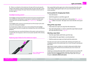 68
68 69
69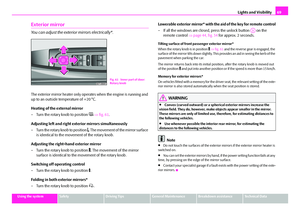 70
70 71
71 72
72 73
73 74
74 75
75 76
76 77
77 78
78 79
79 80
80 81
81 82
82 83
83 84
84 85
85 86
86 87
87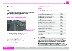 88
88 89
89 90
90 91
91 92
92 93
93 94
94 95
95 96
96 97
97 98
98 99
99 100
100 101
101 102
102 103
103 104
104 105
105 106
106 107
107 108
108 109
109 110
110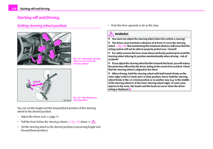 111
111 112
112 113
113 114
114 115
115 116
116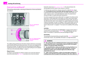 117
117 118
118 119
119 120
120 121
121 122
122 123
123 124
124 125
125 126
126 127
127 128
128 129
129 130
130 131
131 132
132 133
133 134
134 135
135 136
136 137
137 138
138 139
139 140
140 141
141 142
142 143
143 144
144 145
145 146
146 147
147 148
148 149
149 150
150 151
151 152
152 153
153 154
154 155
155 156
156 157
157 158
158 159
159 160
160 161
161 162
162 163
163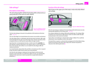 164
164 165
165 166
166 167
167 168
168 169
169 170
170 171
171 172
172 173
173 174
174 175
175 176
176 177
177 178
178 179
179 180
180 181
181 182
182 183
183 184
184 185
185 186
186 187
187 188
188 189
189 190
190 191
191 192
192 193
193 194
194 195
195 196
196 197
197 198
198 199
199 200
200 201
201 202
202 203
203 204
204 205
205 206
206 207
207 208
208 209
209 210
210 211
211 212
212 213
213 214
214 215
215 216
216 217
217 218
218 219
219 220
220 221
221 222
222 223
223 224
224 225
225 226
226 227
227 228
228 229
229 230
230 231
231 232
232 233
233 234
234 235
235 236
236 237
237 238
238 239
239 240
240 241
241 242
242 243
243 244
244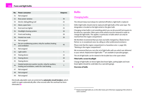 245
245 246
246 247
247 248
248 249
249 250
250 251
251 252
252 253
253 254
254 255
255 256
256 257
257 258
258 259
259 260
260 261
261 262
262 263
263 264
264 265
265 266
266 267
267 268
268 269
269 270
270 271
271