Page 105 of 272
 Owners Manual The air conditioning system
104
Automatic air distribution control*
When the automatic air distribution control is switched on, an air
quality sensor measures the concentration of pollutants in the d")
The air conditioning system
104
Automatic air distribution control*
When the automatic air distribution control is switched on, an air
quality sensor measures the concentration of pollutants in the drawn
in air.
If a considerable increase in concentr ation of pollutants is recognized by
the air quality sensor, the air distribution control will temporarily be
switched off. If the concentration of pollutants decreases to the normal
level, the air distribution control is au tomatically switched off so that fresh
air can be guided into the vehicle interior.
Switch on automatic air distribution control
– Press the button repeatedly * until the warning light on the right side of the button lights up.
Switch off automatic air distribution control temporarily
– If the air quality sensor does not switch on automatically when there is a nauseating smell, you can switch it on yourself by pressing the
button *. The warning light lights up in the button on the left side.
Switch on automatic air distribution control again
– Hold the button pressed * for more than 2 seconds and on the right side of the button the warning light lights up.
Switch off automatic air distribution control
– Press again the button * until the warning lights in the button go out.
WARNING
You should not leave recirculated air mode on over a longer period of time,
as “stale” air may result in fatigue in the driver and occupants, divert your
attention and also cause the windows to mist up. The risk of having an acci- dent increases. Switch recirculated air mode off as soon as the windows
begin misting up.
Note
•If the windscreen mists up, press the button
⇒page 102, fig. 113 .
After the windscreen has been demisted, press the button .
•The automatic air distribution control operates only if the outside temperature
is higher than approx. 2°C.
Controlling blower
There are a total of seven blower stages available.
The Climatronic system controls the bl ower stages automatically in line
with the interior temperature. You can also, however, adapt the blower
stages manually to suit your particular needs.
– Press again the button
on the left side (reduce blower speed) or on
the right side (increase blower speed).
If you switch off the blower, th e Climatronic is switched off.
The set blower speed is displayed above the button
when the respective
number of warning lights come on.
WARNING
•“Stale air” may result in fatigue in the driver and occupants, reduce
attention levels and also cause the windows to mist up. The risk of having an
accident increases.
•Do not switch the Climatronic syst em off for longer than necessary.
•Switch the Climatronic system on as soon as the windows mist up.
WARNING (continued)
A1AUTO
NKO B6 20.book Page 104 Wednesday, March 26, 2008 3:15 PM
Page 106 of 272
 Owners Manual The air conditioning system105
Using the systemSafetyDriving TipsGeneral MaintenanceBreakdown assistanceTechnical Data
Defrosting windscreen
Defrosting windscreen - switching on
– Press the button")
The air conditioning system105
Using the systemSafetyDriving TipsGeneral MaintenanceBreakdown assistanceTechnical Data
Defrosting windscreen
Defrosting windscreen - switching on
– Press the button ⇒page 102, fig. 113 .
Defrosting windscreen - switching off
– Once again press the button or the button .
The temperature control is controlled automatically. More air flows out of the air
outlet vents 1.
Air outlet vents
Fig. 114 Air vents at the front Fig. 115 Air vents at the rear
Open air outlet vents
– Turn the rotary knob to position
.
Close air outlet vents
– Turn the rotary knob to position 0.
Redirecting air flow
– The horizontal as well as the vertical direction of the air flow is set with the handle in the middle of the air outlet vents.
You can control the air distribution to the air outlet vents via the buttons of the
operating part of the Climatronic ⇒page 102. Air outlet vents 2, 3 ⇒ fig. 114 and 5
⇒ fig. 115 can also be opened or closed individually.
Note
The air outlet vents 1 ensure in the ventilation and cooling mode for a comfortable
(no-draught) ventilation of the interior of the vehicle, also if the air outlet vents 3
are closed.
AUTO
NKO B6 20.book Page 105 Wednesday, March 26, 2008 3:15 PM
Page 107 of 272
 Owners Manual The air conditioning system
106
Auxiliary heating (auxiliary heating and ventilation)*
Description and important information
The auxiliary heating (auxiliary he ating and ventilation) heats or
suppli")
The air conditioning system
106
Auxiliary heating (auxiliary heating and ventilation)*
Description and important information
The auxiliary heating (auxiliary he ating and ventilation) heats or
supplies the interior of the vehicl e with fresh air independent of the
engine.
Auxiliary heating (auxiliary heating)
The auxiliary heating (auxiliary heating) func tions in connection with the Climatic or
Climatronic.
It can be used when stationary, when engi ne is switched off for preheating of the
vehicle as well as while driving (e.g. during the heating phase of the engine).
The auxiliary heating (auxiliary heating) warms up the coolant during the combus-
tion of fuel from the vehicle tank. The coolant warms up the air, which (if the blower
speed is not set to zero) flows into the occupant compartment.
10)
Auxiliary ventilation
The auxiliary ventilation enables fresh air to flow into the vehicle interior by
switching off the engine, whereby the interior temperature is effectively decreased
(e.g. with the vehicle parked in the sun).
WARNING
•The auxiliary heating must never be op erated in closed rooms - risk of
poisoning!
•The auxiliary heating must not be running during refueling - risk of fire.
•The exhaust pipe of the auxiliary heating is located on the underside of
the vehicle. Therefore do not place the vehicle, if you wish to operate the
auxiliary heating, in such a way that the exhaust gases of the auxiliary
heating can come easily into contact with inflammable materials (e.g. dry
grass) or easily inflammable substances (e.g. fuel run out).
Note
•If the auxiliary heating runs, the fuel consumption comes from the vehicle tank.
Therefore the auxiliary heating should not be operated, if there is very little fuel in
the tank.
•The exhaust pipe of the auxiliary heatin g, which is located on the underside of
the vehicle, must not be clogged and the exhaust flow must not be blocked.
•If the auxiliary heating and ventilation is running, the vehicle battery discharges.
If the auxiliary heating and ventilation has been operated several times over a
longer period, the vehicle must be driven a few kilometers in order to recharge the
vehicle battery.
•The auxiliary heating only switches the blower on, if it has achieved a coolant
temperature of approx. 50 °C.
•At low outside temperatures, this can result in a formation of water vapour in
the area of the engine compartment. This is quite normal and is not an operating
problem.
•After switching off the auxiliary heating, the coolant pump runs for a short
period.
•The auxiliary heating and ventilation does not switch on or comes on, if the
vehicle battery indicates a low loading state.
•The auxiliary heating (auxiliary heating) switches off, if in the information
display: Please refuel! is indicated or wa s indicated before switching off the igni-
tion.
•When driving, the auxiliary heating can only be switched on, if the exterior
temperature is lower than 5 °C.
•The air inlet in front of the windscreen must be free of ice, snow or leaves in
order to ensure that the auxili ary heating operates properly.
•So that warm air can flow into the vehi cle interior after switching on the auxil-
iary heating, you must maintain the te mperature normally selected by you (we
recommend 22°C). It is recommended to put the air flow in the position
.
•On vehicles with DPF (diesel particle filter) the warm coolant heats up the
engine.
10)However the coolant does not warm up the engine.
NKO B6 20.book Page 106 Wednesday, March 26, 2008 3:15 PM
Page 108 of 272
 Owners Manual The air conditioning system107
Using the systemSafetyDriving TipsGeneral MaintenanceBreakdown assistanceTechnical Data
Using the system
So that the auxiliary heating (auxiliary heating and ventilation")
The air conditioning system107
Using the systemSafetyDriving TipsGeneral MaintenanceBreakdown assistanceTechnical Data
Using the system
So that the auxiliary heating (auxiliary heating and ventilation) func-
tions according to your expectations, it is necessary to carry out the
basic setting before its programming.
Basic setting
– In the information display, select from the menu Main menu the
Menu Setup (settings) .
– In the menu Settings select the menu Aux. heating.
– In the menu Aux. heating ⇒ fig. 116 select the menu Weekday and
set the current day.
– Return to a higher level by selecting the menu Back, i. e. in the menu
Aux. Heating .
– In the menu Aux. Heating select the menu Running time and set the
desired operating period in steps of 1 minute. The operating period
can be 5 to 60 minutes.
– Return to a higher level by selecting the menu Back in the menu
Aux. heating .
– In the menu Aux. heating select the menu Mode . – In the menu
Mode select the desired mode Heating or Ventilation .
Programming
For the programming of the auxiliary heating (auxiliary heating and ventilation) in
the menu Aux. heating there are three pre-set times:
•Pre-set time 1
•Pre-set time 2
•Pre-set time 3
In each pre-set time, the day (if necessary each day = daily) and the time (hour and
minute) can be set for the operating period of the auxiliary heating and/or ventila-
tion.
If you leave the pre-set menu by selecting menu Back or do not operate the display
for longer than 10 seconds, the set values are stored, but the pre-set time is not
active.
Both other pre-set times can be prog rammed and stored in the same way.
If you select the menu Activate after setting the desired values, Pre-set time
(weekday, hours, minute) activated! is displayed in the display and the set pre-
set time is active.
Only one programmed pre-set time can be active.
The last programmed pre-set time remains active.
The active pre-set time can be changed in the menu Aux. heating in the menu
Activation by selecting a pre-set time.
The prerequisite for the correct switching on of the auxiliary heating (auxiliary
heating and ventilation) according to th e programmed pre-set time is the correct
setting of the current time and the weekday ⇒page 107.
If the system is running, a warning light in the button for direct switching on/off of
the auxiliary heating lights up.
The running system deactivates after expiration of the operating period or is deac-
tivated earlier by pres sing the button for direct swit ching on/off of the auxiliary
heating ⇒page 109.
Fig. 116 Information
display: Aux. Heating (auxil-
iary heating)
NKO B6 20.book Page 107 Wednesday, March 26, 2008 3:15 PM
Page 109 of 272
 Owners Manual The air conditioning system
108
The deactivation of a desired pre-set time can be performed by selecting the menu
Deactive in the menu Active .
It is possible to re-establish the factory setting us")
The air conditioning system
108
The deactivation of a desired pre-set time can be performed by selecting the menu
Deactive in the menu Active .
It is possible to re-establish the factory setting using the menu Factory setting in
the menu Aux. heating .
Radio remote control
The auxiliary heating (auxiliary heating and ventilation) can be
switched on or off with the remote control.
– For switching on, press the button .
– For switching off, press the button .
The transmitter and the battery are housed in the housing of the remote control.
The receiver is located in the interior of the car.
If the battery is properly charged, the ef fective range is up to 600 m. For switching
on or off the auxiliary heating, hold the remote control vertically with the antenna
⇒ fig. 117 towards the top. You must not cover over the antenna with the
fingers or the palm of th e hand. Obstacles between the remote control and the
vehicle, bad weather conditio ns and a weaker battery can clearly reduce the range.
The auxiliary heating can only be switched on or off with the remote control, if the
distance between the remote control and the vehicle is at least 2 m. Warning light in the remote control
The warning light in the remote control
⇒fig. 117 indicates after a keystroke if the
remote control signal was received by th e auxiliary heating and if the battery is
adequately charged.Caution
There are electronic components in the remote control, protect the remote control
against water, severe shoc ks and direct sun rays.
Changing the battery of the radio remote control
If the warning light of the remote control indicates a weak or discharged
battery, ⇒fig. 117 , it must be replaced. The battery is located under a
cover on the back of the remote control.
Fig. 117 Auxiliary heating:
Radio remote control
ON
OFF
AA
Display warning lightImportance
Lights up green for 2 seconds.The auxiliary heating was switched on.
Lights up red for 2 seconds.The auxiliary heating was switched off.
Slowly flashes green for 2 seconds.The ignition signal was not received.
Quickly flashes green for 2 seconds.The auxiliary heating is blocked, e. g
because the tank is nearly empty or
there is a fault in the auxiliary heating.
Flashes red for 2 seconds.The switch off signal was not received.
Lights up orange for 2 seconds, then
green or red.The battery is weak, however the
switching on or off signal was received.
Lights up orange for 2 seconds, then
flashes green or red.The battery is weak, however the
switching on or off signal was not
received.
Flashes orange for 5 seconds.The battery is discharged, however the
switching on or off signal was not
received.
NKO B6 20.book Page 108 Wednesday, March 26, 2008 3:15 PM
Page 110 of 272
 Owners Manual The air conditioning system109
Using the systemSafetyDriving TipsGeneral MaintenanceBreakdown assistanceTechnical Data
– Place a coin into the gap of the battry cover and by turning to the left,
un")
The air conditioning system109
Using the systemSafetyDriving TipsGeneral MaintenanceBreakdown assistanceTechnical Data
– Place a coin into the gap of the battry cover and by turning to the left,
unlock the cover.
– Change the battery, insert the cover and lock it by turning to the right.
For the sake of the environment
Dispose of an old battery in accordance with environm ental regulations.
Note
•Pay attention to the correct polarity when changing the battery.
•The replacement battery must have the same specification as the original
battery.
Direct switching on/off
The auxiliary heating (auxiliary heating and ve ntilation) can be switched on or off at
any time directly using the button on the operating part of the Climatic
⇒ fig. 118 or on the operating part of the Climatronic.
The auxiliary heating system (auxiliary heating and ventilation) switches off auto-
matically after expiration of the set operating period in the menu Running time, if
it is not switched of f beforehand by you.
Fig. 118 Button for direct
switching on/off of the auxil-
iary heating (auxiliary
heating and ventilation) on
the operating part of the
Climatic
NKO B6 20.book Page 109 Wednesday, March 26, 2008 3:15 PM
Page 111 of 272
 Owners Manual Starting-off and Driving
110
Starting-off and Driving
Setting steering wheel position
You can set the height and the forward/back position of the steering
wheel to the desired position.
– Adjust th")
Starting-off and Driving
110
Starting-off and Driving
Setting steering wheel position
You can set the height and the forward/back position of the steering
wheel to the desired position.
– Adjust the driver seat ⇒page 71.
– Pull the lever below the steering column ⇒fig. 119 down ⇒.
– Set the steering wheel to the desired position (concerning height and forward/back position). – Push the lever upwards as far as the stop.
WARNING
•You must not adjust the steering wh
eel when the vehicle is moving!
•The driver must maintain a distance of at least 25 cm to the steering
wheel ⇒fig. 120 . Not maintaining this minimum distance will mean that the
airbag system will not be able to properly protect you - hazard!
•For s afe ty re a so ns t he le ve r m ust al wa y s b e fi rm ly pus he d up to a voi d the
steering wheel alteri ng its position unintentionally when driving - risk of
accident!
•If you adjust the steering wheel furthe r towards the head, you will reduce
the protection offered by the driver airb ag in the event of an accident. Check
that the steering wheel is aligned to the chest.
•When driving, hold the steering wheel with both hands firmly on the
outer edge in the 9 o'clock and 3 o'clock position. Never hold the steering
wheel firmly in the 12 o'clock position or in another way (e.g. in the middle
of the steering wheel or at the inner steering wheel edge). In such cases,
injuries to the arms, the hands and the head can occur when the driver
airbag is deployed.
Fig. 119 Adjustable steering
wheel: Lever next to the
steering column
Fig. 120 Safe distance to
steering wheel
NKO B6 20.book Page 110 Wednesday, March 26, 2008 3:15 PM
Page 112 of 272
 Owners Manual Starting-off and Driving111
Using the systemSafetyDriving TipsGeneral MaintenanceBreakdown assistanceTechnical Data
Ignition lock
Petrol engines
- ignition switched off, engine off, the steering can")
Starting-off and Driving111
Using the systemSafetyDriving TipsGeneral MaintenanceBreakdown assistanceTechnical Data
Ignition lock
Petrol engines
- ignition switched off, engine off, the steering can be locked
- ignition switched on
- start engine
Diesel engines - interruption of fuel supply, ignition switched off, engine off, the steering can
be locked.
- heating glow plugs on, ignition switched on
•You should not switch on any major elec trical components during the heating
period otherwise the vehicle batter y will be drained unnecessarily.
- start engine
Applies to all models:
Position
To lock the steering , with the ignition key withdrawn, turn the steering wheel until
the steering locking pin is heard to engage. You should always lock the steering as
a general rule if you leave your vehicle. This acts as a deterrent against possible theft
of your vehicle ⇒.
Position Move the steering wheel back and forward
a little if the ignition key cannot, or
cannot easily be turned into this position, in order to release the steering lock.
Position
The engine is started in this position. At the same time switched on low beam or
main beam or other electrical compon ents with major power consumption are
briefly switched off. The ignition key moves back into position when one
releases the key.
The ignition key must be turned back into position each time before starting the
engine again. The starter repeat lock in th e ignition lock prevents the starter being
engaged when the engine is ru nning and thus getting damaged.
Ignition key withdrawal lock (automatic gearbox)
You can only withdraw the ignition key after switching off the ignition if the selector
lever is in position P.
WARNING
•When driving, the ignition key must always be in the position (igni-
tion switched on) without the engine running. This position is indicated by
the warning lights coming on. If this is not the case, it could result in unex-
pected locking of the steering wheel - risk of accident!
•Only remove the ignition key from the ignition lock when the vehicle has
come to a standstill (put on the handbrake or select the selector lever posi-
tion P). The steering lock can enga ge immediately - risk of accident!
•Always withdraw the ignition key if you are going to leave the vehicle,
even for a short time. This is particularly important if children are left in the
vehicle. The children might otherwise star t the engine or switch on electrical
equipment (e.g. power windows) - risk of accident or injury!
Fig. 121 Ignition lock posi-
tions
A1
A2
A3
A1
A2
A3
A1
A2
A3
A2
A1
A2
NKO B6 20.book Page 111 Wednesday, March 26, 2008 3:15 PM
 1
1 2
2 3
3 4
4 5
5 6
6 7
7 8
8 9
9 10
10 11
11 12
12 13
13 14
14 15
15 16
16 17
17 18
18 19
19 20
20 21
21 22
22 23
23 24
24 25
25 26
26 27
27 28
28 29
29 30
30 31
31 32
32 33
33 34
34 35
35 36
36 37
37 38
38 39
39 40
40 41
41 42
42 43
43 44
44 45
45 46
46 47
47 48
48 49
49 50
50 51
51 52
52 53
53 54
54 55
55 56
56 57
57 58
58 59
59 60
60 61
61 62
62 63
63 64
64 65
65 66
66 67
67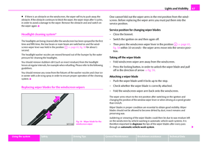 68
68 69
69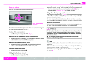 70
70 71
71 72
72 73
73 74
74 75
75 76
76 77
77 78
78 79
79 80
80 81
81 82
82 83
83 84
84 85
85 86
86 87
87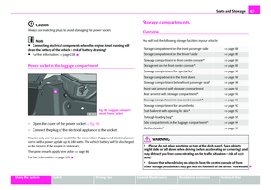 88
88 89
89 90
90 91
91 92
92 93
93 94
94 95
95 96
96 97
97 98
98 99
99 100
100 101
101 102
102 103
103 104
104 105
105 106
106 107
107 108
108 109
109 110
110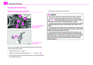 111
111 112
112 113
113 114
114 115
115 116
116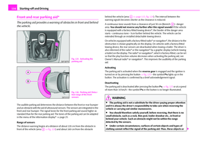 117
117 118
118 119
119 120
120 121
121 122
122 123
123 124
124 125
125 126
126 127
127 128
128 129
129 130
130 131
131 132
132 133
133 134
134 135
135 136
136 137
137 138
138 139
139 140
140 141
141 142
142 143
143 144
144 145
145 146
146 147
147 148
148 149
149 150
150 151
151 152
152 153
153 154
154 155
155 156
156 157
157 158
158 159
159 160
160 161
161 162
162 163
163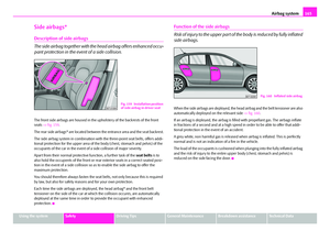 164
164 165
165 166
166 167
167 168
168 169
169 170
170 171
171 172
172 173
173 174
174 175
175 176
176 177
177 178
178 179
179 180
180 181
181 182
182 183
183 184
184 185
185 186
186 187
187 188
188 189
189 190
190 191
191 192
192 193
193 194
194 195
195 196
196 197
197 198
198 199
199 200
200 201
201 202
202 203
203 204
204 205
205 206
206 207
207 208
208 209
209 210
210 211
211 212
212 213
213 214
214 215
215 216
216 217
217 218
218 219
219 220
220 221
221 222
222 223
223 224
224 225
225 226
226 227
227 228
228 229
229 230
230 231
231 232
232 233
233 234
234 235
235 236
236 237
237 238
238 239
239 240
240 241
241 242
242 243
243 244
244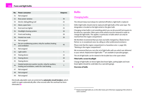 245
245 246
246 247
247 248
248 249
249 250
250 251
251 252
252 253
253 254
254 255
255 256
256 257
257 258
258 259
259 260
260 261
261 262
262 263
263 264
264 265
265 266
266 267
267 268
268 269
269 270
270 271
271