Page 17 of 94

ENGINE COMPARTMENT CONNECTION UNIT
Fault finding - Interpretation of faults87G
87G-17V7 MR-372-J84-87G050$330.mif
UPC
Vdiag No.: 48, 4C
DF007
PRESENT
OR
STOREDUPC - ALTERNATOR CONNECTION
CO: Open circuit
CC: Short circuit to earth
1.DEF: Communication disrupted
NOTESSpecial notes:
–Check the conformity of the wiring (see Test no. 2 Wiring test).
Repair if necessary.
–The fault illuminates the Battery charge warning light on the instrument panel and
the STOP warning light.
–Conditions for applying the fault finding procedure to stored faults:
The fault is declared present after the engine has been running for 10 minutes.
Use Wiring Diagrams Technical Note for Mégane II or Scénic II.
CO
NOTES+ APC.
Engine stopped.
Disconnect the UPC-Alternator connection for the alternator component code 103.
Check the connection and condition of the alternator connector, component code 103.
If the connector is faulty and if there is a repair procedure (see Technical Note 6015A, Electrical wiring repair,
Wiring: Precautions for repair), repair the connector, otherwise replace the connector.
Measure the voltage on connection 2N between the alternator, component code 103 and the battery earth,
component code 107.
If the voltage is less than 3 V
Check the connection and condition of connector MT1 for the Protection and Switching Unit, component code
1337.
If the connector is faulty and if there is a repair procedure (see Technical Note 6015A, Electrical wiring repair,
Wiring: Precautions for repair), repair the connector, otherwise replace the connector.
Check the insulation, continuity and the absence of interference resistance on the following connection:
–2N between components 1337 and 103.
If the connection is faulty and if there is a repair procedure (see Technical Note 6015A, Electrical wiring repair,
Wiring: Precautions for repair), repair the wiring otherwise replace the wiring.
If the fault is still present, replace the Protection and Switching Unit (see Replacement of components).
AFTER REPAIRErase the faults from the computer memory, switch the + after ignition supply off and
back on again, and run another check using the diagnostic tool after 10 minutes
with the engine running.
USM_V48_DF007/USM_V4C_DF007
Page 18 of 94

ENGINE COMPARTMENT CONNECTION UNIT
Fault finding - Interpretation of faults87G
87G-18V7 MR-372-J84-87G050$330.mif
UPC
Vdiag No.: 48, 4C
DF007
CONTINUED 1
If the voltage is greater than 9 V
Replace the Protection and Switching Unit (see Replacement of components).
If the voltage is greater than or equal to 3 V and less than or equal to 9 V
If the voltage is greater than or equal to 3 V and less than or equal to 9 V:
Use an oscilloscope to record the presence of a square pulse signal on connection 2N between the alternator,
component code 103 and the Protection and Switching Unit, component code 1337 on the alternator side.
Connect the oscilloscope between the connector of the UPC- alternator connection on the alternator side and the
battery earth, component code 107.
Adjust the oscilloscope:
–calibration: 2.5 V/div,
–time base: 2 ms/div.
AFTER REPAIRErase the faults from the computer memory, switch the + after ignition supply off and
back on again, and run another check using the diagnostic tool after 10 minutes
with the engine running.
Page 19 of 94
ENGINE COMPARTMENT CONNECTION UNIT
Fault finding - Interpretation of faults87G
87G-19V7 MR-372-J84-87G050$330.mif
UPC
Vdiag No.: 48, 4C
DF007
CONTINUED 2
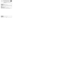
Perform three successive acquisitions at intervals of 10 to 15 seconds.
Check that the signal resembles the image above.
If so:
Replace the alternator (see MR 364 or 370 Mechanical, 16A, Starting - Charging, Alternator: Removal -
Refitting).
Otherwise:
Contact Techline.
MULTIMETER
UNIVERSAL SCOPE
TIME BASE
2 ms/div
TRIGGER
AUTO
RANGE
2.5 V/div
AFTER REPAIRErase the faults from the computer memory, switch the + after ignition supply off and
back on again, and run another check using the diagnostic tool after 10 minutes
with the engine running.
Page 20 of 94

ENGINE COMPARTMENT CONNECTION UNIT
Fault finding - Interpretation of faults87G
87G-20V7 MR-372-J84-87G050$330.mif
UPC
Vdiag No.: 48, 4C
DF007
CONTINUED 3
1.DEF
NOTESNone.
Check the connection and condition of the alternator connector, component code 103.
If the connector is faulty and if there is a repair procedure (see Technical Note 6015A, Electrical wiring repair,
Wiring: Precautions for repair), repair the connector, otherwise replace the connector.
Check the connection and condition of connector MT1 for the Protection and Switching Unit, component code
1337.
If the connector is faulty and if there is a repair procedure (see Technical Note 6015A, Electrical wiring repair,
Wiring: Precautions for repair), repair the connector, otherwise replace the connector.
With the engine running, switch on the electrical heated rear screen.
Measure the voltage between the earth of the alternator casing component code 103 and the battery earth
component code 107.
If the difference is over 1 V, check the vehicle earths.
If the fault is still present, contact the Techline.
AFTER REPAIRErase the faults from the computer memory, switch the + after ignition supply off and
back on again and run another check using the diagnostic tool.
Page 21 of 94

ENGINE COMPARTMENT CONNECTION UNIT
Fault finding - Interpretation of faults87G
87G-21V7 MR-372-J84-87G050$330.mif
UPC
Vdiag No.: 48, 4C
DF007
CONTINUED 4
CC
NOTESNone.
Check the connection and condition of the alternator connector, component code 103.
If the connector is faulty and if there is a repair procedure (see Technical Note 6015A, Electrical wiring repair,
Wiring: Precautions for repair), repair the connector, otherwise replace the connector.
Check the connection and condition of connector MT1 for the Protection and Switching Unit, component code
1337.
If the connector is faulty and if there is a repair procedure (see Technical Note 6015A, Electrical wiring repair,
Wiring: Precautions for repair), repair the connector, otherwise replace the connector.
Disconnect the UPC-Alternator connection for the alternator and the Protection and Switching Unit.
Ensure that the UPC-Alternator connection is insulated in relation to the + 12V supply and the earth:
–2N between components 1337 and 103.
If the connection is faulty and if there is a repair procedure (see Technical Note 6015A, Electrical wiring repair,
Wiring: Precautions for repair), repair the wiring otherwise replace the wiring.
If the fault is still present, disconnect the connector from the Protection and Switching Unit.
In + after ignition feed, measure the voltage of the connector MT1 for the Protection and Switching Unit on
connection code 2N.
If the voltage is less than 3V or greater than 9V:
Replace the Protection and Switching Unit (see Replacement of components).
If the voltage is between 3V and 9V:
Replace the alternator (see MR 364 or MR 370 Mechanical, 16A, Starting - Charging, Alternator: Removal -
Refitting).
AFTER REPAIRErase the faults from the computer memory, switch the + after ignition supply off and
back on again and run another check using the diagnostic tool.
Page 22 of 94

ENGINE COMPARTMENT CONNECTION UNIT
Fault finding - Interpretation of faults87G
87G-22V7 MR-372-J84-87G050$330.mif
UPC
Vdiag No.: 4C
DF009
PRESENT
OR
STORED+ APC CIRCUIT
1.DEF: Permanent low level
2.DEF: Permanent high signal
NOTESSpecial note:
This fault only applies to Vdiag 4C.
Conditions for applying the fault finding procedure to present faults:
The fault is declared present after the ignition has been switched on.
Use Wiring Diagrams Technical Note for Mégane II or Scénic II.
Check the connection and condition of the LPG electric control unit connector, component code 997.
Check for a voltage on connection AP31 to the connector for the LPG electric control unit, component code 997.
If the connection is faulty and if there is a repair procedure (see Technical Note 6015A, Electrical wiring repair,
Wiring: Precautions for repair), repair the wiring otherwise replace the wiring.
Check the connection and condition of the multifunction switch, the reverse gear switch and the manual
gearbox neutral sensor/reversing lights, component codes 485, 155, and 1109.
Check for a voltage on connection AP11 to the connectors for the multifunction switch, the reverse gear switch
and the manual gearbox neutral sensor/reverse lights, component codes 485, 155, and 1109.
If the connection is faulty and if there is a repair procedure (see Technical Note 6015A, Electrical wiring repair,
Wiring: Precautions for repair), repair the wiring otherwise replace the wiring.
Check the connection and condition of the passenger compartment electric control unit, component code 645.
Check for a voltage on connection APCB to the connector for the passenger compartment electric control unit,
component code 645.
If the connection is faulty and if there is a repair procedure (see Technical Note 6015A, Electrical wiring repair,
Wiring: Precautions for repair), repair the wiring otherwise replace the wiring.
Check the connection and condition of the electric steering column lock, component code 1088.
Check for a voltage on connection AP15 to the connector for the electric steering column lock, component code
1088.
If the connection is faulty and if there is a repair procedure (see Technical Note 6015A, Electrical wiring repair,
Wiring: Precautions for repair), repair the wiring otherwise replace the wiring.
Check the connection and condition of the airbag/pretensioner electric control unit and the electric power-
assisted steering system, component codes 756 and 1232.
Check for a voltage on connection AP44 to the connectors for the airbag/pretensioner electric control unit and
the electric power-assisted steering system connectors, component codes 756 and 1232.
If the connection is faulty and if there is a repair procedure (see Technical Note 6015A, Electrical wiring repair,
Wiring: Precautions for repair), repair the wiring otherwise replace the wiring.
AFTER REPAIRErase the faults from the computer memory, switch the + after ignition supply off and
back on again and run another check using the diagnostic tool.
USM_V4C_DF009
Page 23 of 94

ENGINE COMPARTMENT CONNECTION UNIT
Fault finding - Interpretation of faults87G
87G-23V7 MR-372-J84-87G050$330.mif
UPC
Vdiag No.: 4C
DF009
CONTINUED
Check the connection and condition of the passenger compartment fuse and relay box, the gear lever display,
the steering column top control module, the additional heater relay 1 and 2, the diagnostic socket, the
parking distance control ECU, the right and left-hand rear electric window switch, the radio, the electric
door mirror control, the front and rear electric window locking controls and the passenger electric window
switch, component codes 260, 1129, 1546, 1067, 1068, 225, 1222, 130, 131, 261, 134, 135, 1511, 1512
and 133.
Check for a voltage on connection AP43 to the connectors for the passenger compartment fuse and relay box,
the gear lever display, the steering column top control module, the additional heater relay 1 and 2, the
diagnostic socket, the parking distance control ECU, the right and left-hand rear electric window switch,
the radio, the electric door mirror control, the front and rear electric window locking controls, the
passenger electric window switch, component codes 260, 1129, 1546, 1067, 1068, 225, 1222, 130, 131, 261,
134, 135, 1511, 1512 and 133.
If the connection or connections are faulty and if there is a repair procedure (see Technical Note 6015A, Electrical
wiring repair, Wiring: Precautions for repair), repair the wiring, otherwise replace it.
Check the insulation, continuity and the absence of interference resistance on the following connections:
–AP31 between components 1337 and 997,
–AP11 between components 1337, 485, 155 and 1109,
–APCB between components 1337 and 645,
–AP15 between components 1337 and 1088,
–AP44 between components 1337, 756 and 1232,
–AP43 between components 1337, 260, 1129, 1546, 1067, 1068, 225, 1222, 130, 131, 261, 134, 135, 1511, 1512
and 133.
If the connections are faulty and if there is a repair procedure (see Technical Note 6015A, Electrical wiring
repair, Wiring: Precautions for repair), repair the wiring, otherwise replace it.
Check the connection and condition of the Protection and Switching Unit, component code 1337.
If the connector is faulty and if there is a repair procedure (see Technical Note 6015A, Electrical wiring repair,
Wiring: Precautions for repair), repair the connector, otherwise replace the connector.
If the fault is still present, contact the Techline.
AFTER REPAIRErase the faults from the computer memory, switch the + after ignition supply off and
back on again and run another check using the diagnostic tool.
Page 24 of 94

ENGINE COMPARTMENT CONNECTION UNIT
Fault finding - Interpretation of faults87G
87G-24V7 MR-372-J84-87G050$330.mif
UPC
Vdiag No.: 48, 4C
DF012
PRESENT
OR
STOREDALTERNATOR
1.DEF: Alternator mechanical or electrical fault
NOTESConditions for applying the fault finding procedure to present faults:
The fault is declared present after the engine has been running for at least 1 minute.
Special note:
The fault illuminates the Battery and STOP warning lights on the instrument panel.
Use Wiring Diagrams Technical Note for Mégane II or Scénic II.
1.DEF
NOTESNone.
Check the fitting, condition and tension of the accessories drive belt.
Visually check that the alternator is not clogged.
Clean out the alternator cooling vents using an air gun.
Check the wiring, the connections and the earths (see Test no. 1 Wiring test).
If the connection is faulty and if there is a repair procedure (see Technical Note 6015A, Electrical wiring repair,
Wiring: Precautions for repair), repair the wiring otherwise replace the wiring.
Run command AC014 Alternator regulation (see Interpretation of commands).
With the bonnet closed, start the engine.
Leave the engine to run for 2 minutes at idle speed.
If the fault is still present, replace the alternator (see MR 364 or MR 370 Mechanical, 16A, Starting - Charging,
Alternator: Removal - Refitting).
AFTER REPAIRErase the faults from the computer memory, switch the + after ignition supply off and
back on again and run another check using the diagnostic tool.
USM_V48_DF012/USM_V4C_DF012