2008 NISSAN TIIDA stc
[x] Cancel search: stcPage 1 of 2771

-1
QUICK REFERENCE INDEX
AGENERAL INFORMATIONGIGeneral Information
BENGINEEMEngine Mechanical
LUEngine Lubrication System
COEngine Cooling System
ECEngine Control System
FLFuel System
EXExhaust System
ACCAccelerator Control System
CTRANSMISSION/
TRANSAXLECLClutch System
MTManual Transaxle
ATAutomatic Transaxle
CVTCVT
DDRIVELINE/AXLEFAXFront Axle
RAXRear Axle
ESUSPENSIONFSUFront Suspension
RSURear Suspension
WTRoad Wheels & Tires
FBRAKESBRBrake System
PBParking Brake System
BRCBrake Control System
GSTEERINGPSPower Steering System
STCSteering Control System
HRESTRAINTSSBSeat Belts
SRSSupplemental Restraint System (SRS)
IBODYBLBody, Lock & Security System
GWGlasses, Window System & Mirrors
RFRoof
EIExterior & Interior
IPInstrument Panel
SESeat
JAIR CONDITIONERMTCManual Air Conditioner
KELECTRICALSCStarting & Charging System
LTLighting System
DIDriver Information System
WWWiper, Washer & Horn
BCSBody Control System
LANLAN System
AVAudio Visual, Navigation & Telephone System
ACSAuto Cruise Control System
PGPower Supply, Ground & Circuit Elements
LMAINTENANCEMAMaintenance
Edition: May 2007
Revision: May 2007
Publication No. SM8E-1C11U0
B
D
© 2007 NISSAN NORTH AMERICA, INC.
All rights reserved. No part of this Service Manual may be reproduced or stored in a retrieval system, or transmitted in any
form, or by any means, electronic, mechanical, photo-copying, recording or otherwise, without the prior written permission
of Nissan North America Inc.
A
C
E
F
G
H
I
J
K
L
M
Page 432 of 2771

BCS-16
< SERVICE INFORMATION >
BCM (BODY CONTROL MODULE)
OK >> GO TO 3.
NG >> Repair or replace the harness.
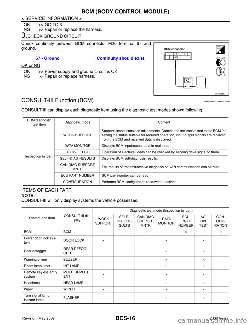
3.CHECK GROUND CIRCUIT
Check continuity between BCM connector M20 terminal 67 and
ground.
OK or NG
OK >> Power supply and ground circuit is OK.
NG >> Repair or replace harness.
CONSULT-III Function (BCM)INFOID:0000000001704590
CONSULT-III can display each diagnostic item using the diagnostic test modes shown following.
ITEMS OF EACH PART
NOTE:
CONSULT-III will only display systems the vehicle possesses.67 - Ground : Continuity should exist.
LIIA0915E
BCM diagnostic
test itemDiagnostic mode Content
Inspection by partWORK SUPPORTSupports inspections and adjustments. Commands are transmitted to the BCM for
setting the status suitable for required operation, input/output signals are received
from the BCM and received data is displayed.
DATA MONITOR Displays BCM input/output data in real time.
ACTIVE TEST Operation of electrical loads can be checked by sending drive signal to them.
SELF-DIAG RESULTS Displays BCM self-diagnosis results.
CAN DIAG SUPPORT
MNTRThe results of transmit/receive diagnosis of CAN communication can be read.
ECU PART NUMBER BCM part number can be read.
CONFIGURATION Performs BCM configuration read/write functions.
System and itemCONSULT-III dis-
playDiagnostic test mode (Inspection by part)
WORK
SUPPORTSELF−
DIAG RE-
SULTSCAN DIAG
SUPPORT
MNTRDATA
MONITORECU
PA R T
NUMBERAC-
TIVE
TESTCON-
FIGU-
RATION
BCM BCM×× × × ×
Power door lock sys-
temDOOR LOCK×××
Rear defoggerREAR DEFOG-
GER××
Warning chime BUZZER××
Room lamp timer INT LAMP×××
Remote keyless entry
systemMULTI REMOTE
ENT×××
Headlamp HEAD LAMP×××
Wiper WIPER×××
Turn signal lamp
Hazard lampFLASHER××
Page 433 of 2771

BCM (BODY CONTROL MODULE)
BCS-17
< SERVICE INFORMATION >
C
D
E
F
G
H
I
J
L
MA
B
BCS
N
O
P
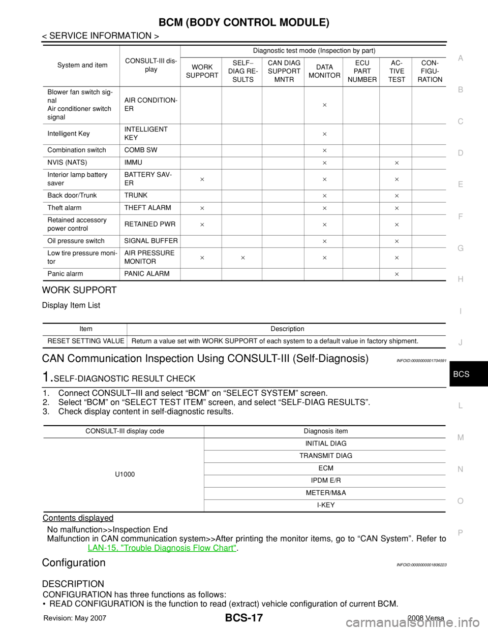
WORK SUPPORT
Display Item List
CAN Communication Inspection Using CONSULT-III (Self-Diagnosis)INFOID:0000000001704591
1.SELF-DIAGNOSTIC RESULT CHECK
1. Connect CONSULT–III and select “BCM” on “SELECT SYSTEM” screen.
2. Select “BCM” on “SELECT TEST ITEM” screen, and select “SELF-DIAG RESULTS”.
3. Check display content in self-diagnostic results.
Contents displayed
No malfunction>>Inspection End
Malfunction in CAN communication system>>After printing the monitor items, go to “CAN System”. Refer to
LAN-15, "
Trouble Diagnosis Flow Chart".
ConfigurationINFOID:0000000001806223
DESCRIPTION
CONFIGURATION has three functions as follows:
• READ CONFIGURATION is the function to read (extract) vehicle configuration of current BCM.
Blower fan switch sig-
nal
Air conditioner switch
signalAIR CONDITION-
ER×
Intelligent KeyINTELLIGENT
KEY×
Combination switch COMB SW×
NVIS (NATS) IMMU××
Interior lamp battery
saverBATTERY SAV-
ER×××
Back door/Trunk TRUNK××
Theft alarm THEFT ALARM×××
Retained accessory
power controlRETAINED PWR×××
Oil pressure switch SIGNAL BUFFER××
Low tire pressure moni-
torAIR PRESSURE
MONITOR×× × ×
Panic alarm PANIC ALARM× System and itemCONSULT-III dis-
playDiagnostic test mode (Inspection by part)
WORK
SUPPORTSELF−
DIAG RE-
SULTSCAN DIAG
SUPPORT
MNTRDATA
MONITORECU
PA R T
NUMBERAC-
TIVE
TESTCON-
FIGU-
RATION
Item Description
RESET SETTING VALUE Return a value set with WORK SUPPORT of each system to a default value in factory shipment.
CONSULT-III display code Diagnosis item
U1000INITIAL DIAG
TRANSMIT DIAG
ECM
IPDM E/R
METER/M&A
I-KEY
Page 873 of 2771

CVT-34
< SERVICE INFORMATION >
TROUBLE DIAGNOSIS
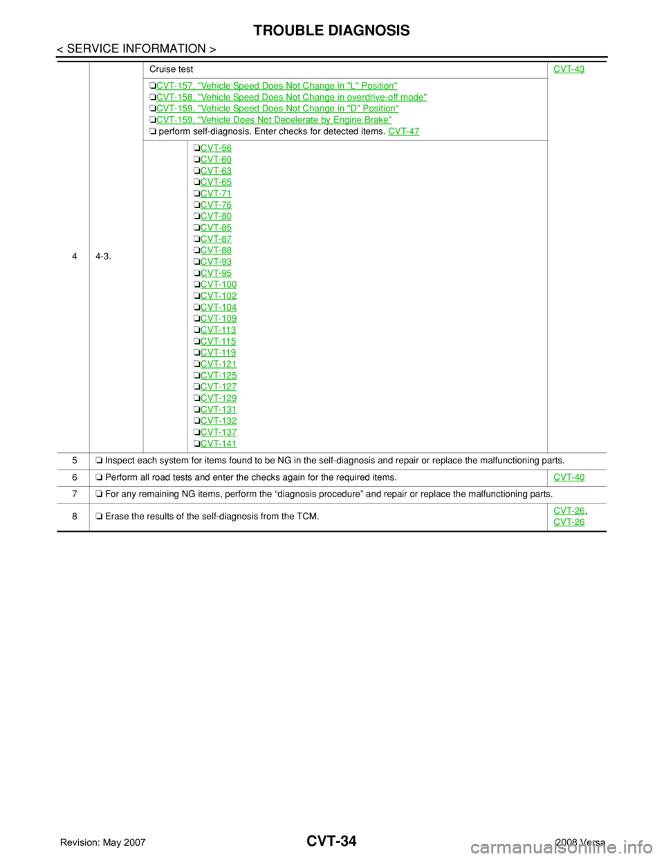
44-3.Cruise testCVT-43
❏CVT-157, "Vehicle Speed Does Not Change in "L" Position"
❏CVT-158, "Vehicle Speed Does Not Change in overdrive-off mode"
❏CVT-159, "Vehicle Speed Does Not Change in "D" Position"
❏CVT-159, "Vehicle Does Not Decelerate by Engine Brake"
❏ perform self-diagnosis. Enter checks for detected items. CVT-47
❏CVT-56
❏CVT-60
❏CVT-63
❏CVT-65
❏CVT-71
❏CVT-76
❏CVT-80
❏CVT-85
❏CVT-87
❏CVT-88
❏CVT-93
❏CVT-95
❏CVT-100
❏CVT-102
❏CVT-104
❏CVT-109
❏CVT-113
❏CVT-115
❏CVT-119
❏CVT-121
❏CVT-125
❏CVT-127
❏CVT-129
❏CVT-131
❏CVT-132
❏CVT-137
❏CVT-141
5❏ Inspect each system for items found to be NG in the self-diagnosis and repair or replace the malfunctioning parts.
6❏ Perform all road tests and enter the checks again for the required items.CVT-40
7❏ For any remaining NG items, perform the “diagnosis procedure” and repair or replace the malfunctioning parts.
8❏ Erase the results of the self-diagnosis from the TCM.CVT-26
,
CVT-26
Page 2027 of 2771
![NISSAN TIIDA 2008 Service Repair Manual LAN-36
< COMPONENT DIAGNOSIS >[CAN]
EPS BRANCH LINE CIRCUIT
EPS BRANCH LINE CIRCUIT
Diagnosis ProcedureINFOID:0000000001711232
INSPECTION PROCEDURE
1.CHECK CONNECTOR
1. Turn the ignition switch OFF.
2 NISSAN TIIDA 2008 Service Repair Manual LAN-36
< COMPONENT DIAGNOSIS >[CAN]
EPS BRANCH LINE CIRCUIT
EPS BRANCH LINE CIRCUIT
Diagnosis ProcedureINFOID:0000000001711232
INSPECTION PROCEDURE
1.CHECK CONNECTOR
1. Turn the ignition switch OFF.
2](/manual-img/5/57399/w960_57399-2026.png)
LAN-36
< COMPONENT DIAGNOSIS >[CAN]
EPS BRANCH LINE CIRCUIT
EPS BRANCH LINE CIRCUIT
Diagnosis ProcedureINFOID:0000000001711232
INSPECTION PROCEDURE
1.CHECK CONNECTOR
1. Turn the ignition switch OFF.
2. Disconnect the battery cable from the negative terminal.
3. Check the terminals and connectors of the EPS control unit for damage, bend and loose connection (unit
side and connector side).
Is the inspection result normal?
YES >> GO TO 2.
NO >> Repair the terminal and connector.
2.CHECK HARNESS FOR OPEN CIRCUIT
1. Disconnect the connector of EPS control unit.
2. Check the resistance between the EPS control unit harness connector terminals.
Is the measurement value within the specification?
YES >> GO TO 3.
NO >> Repair the EPS control unit branch line.
3.CHECK POWER SUPPLY AND GROUND CIRCUIT
Check the power supply and the ground circuit of the EPS control unit. Refer to STC-14, "
DTC C1601 BAT-
TERY VOLT".
Is the inspection result normal?
YES (Present error)>>Replace the EPS control unit. Refer to PS-9, "Removal and Installation".
YES (Past error)>>Error was detected in the EPS control unit branch line.
NO >> Repair the power supply and the ground circuit.
EPS control unit harness connector
Resistance (Ω)
Connector No. Terminal No.
M53 9 16 Approx. 54 – 66
Page 2038 of 2771
![NISSAN TIIDA 2008 Service Repair Manual EPS BRANCH LINE CIRCUIT
LAN-47
< COMPONENT DIAGNOSIS >[CAN SYSTEM (TYPE 1)]
C
D
E
F
G
H
I
J
L
MA
B
LAN
N
O
P
EPS BRANCH LINE CIRCUIT
Diagnosis ProcedureINFOID:0000000001711348
INSPECTION PROCEDURE
1.C NISSAN TIIDA 2008 Service Repair Manual EPS BRANCH LINE CIRCUIT
LAN-47
< COMPONENT DIAGNOSIS >[CAN SYSTEM (TYPE 1)]
C
D
E
F
G
H
I
J
L
MA
B
LAN
N
O
P
EPS BRANCH LINE CIRCUIT
Diagnosis ProcedureINFOID:0000000001711348
INSPECTION PROCEDURE
1.C](/manual-img/5/57399/w960_57399-2037.png)
EPS BRANCH LINE CIRCUIT
LAN-47
< COMPONENT DIAGNOSIS >[CAN SYSTEM (TYPE 1)]
C
D
E
F
G
H
I
J
L
MA
B
LAN
N
O
P
EPS BRANCH LINE CIRCUIT
Diagnosis ProcedureINFOID:0000000001711348
INSPECTION PROCEDURE
1.CHECK CONNECTOR
1. Turn the ignition switch OFF.
2. Disconnect the battery cable from the negative terminal.
3. Check the terminals and connectors of the EPS control unit for damage, bend and loose connection (unit
side and connector side).
Is the inspection result normal?
YES >> GO TO 2.
NO >> Repair the terminal and connector.
2.CHECK HARNESS FOR OPEN CIRCUIT
1. Disconnect the connector of EPS control unit.
2. Check the resistance between the EPS control unit harness connector terminals.
Is the measurement value within the specification?
YES >> GO TO 3.
NO >> Repair the EPS control unit branch line.
3.CHECK POWER SUPPLY AND GROUND CIRCUIT
Check the power supply and the ground circuit of the EPS control unit. Refer to STC-14, "
DTC C1601 BAT-
TERY VOLT".
Is the inspection result normal?
YES (Present error)>>Replace the EPS control unit. Refer to PS-9, "Removal and Installation".
YES (Past error)>>Error was detected in the EPS control unit branch line.
NO >> Repair the power supply and the ground circuit.
EPS control unit harness connector
Resistance (Ω)
Connector No. Terminal No.
M53 9 16 Approx. 54 – 66
Page 2046 of 2771
![NISSAN TIIDA 2008 Service Repair Manual EPS BRANCH LINE CIRCUIT
LAN-55
< COMPONENT DIAGNOSIS >[CAN SYSTEM (TYPE 2)]
C
D
E
F
G
H
I
J
L
MA
B
LAN
N
O
P
EPS BRANCH LINE CIRCUIT
Diagnosis ProcedureINFOID:0000000001711368
INSPECTION PROCEDURE
1.C NISSAN TIIDA 2008 Service Repair Manual EPS BRANCH LINE CIRCUIT
LAN-55
< COMPONENT DIAGNOSIS >[CAN SYSTEM (TYPE 2)]
C
D
E
F
G
H
I
J
L
MA
B
LAN
N
O
P
EPS BRANCH LINE CIRCUIT
Diagnosis ProcedureINFOID:0000000001711368
INSPECTION PROCEDURE
1.C](/manual-img/5/57399/w960_57399-2045.png)
EPS BRANCH LINE CIRCUIT
LAN-55
< COMPONENT DIAGNOSIS >[CAN SYSTEM (TYPE 2)]
C
D
E
F
G
H
I
J
L
MA
B
LAN
N
O
P
EPS BRANCH LINE CIRCUIT
Diagnosis ProcedureINFOID:0000000001711368
INSPECTION PROCEDURE
1.CHECK CONNECTOR
1. Turn the ignition switch OFF.
2. Disconnect the battery cable from the negative terminal.
3. Check the terminals and connectors of the EPS control unit for damage, bend and loose connection (unit
side and connector side).
Is the inspection result normal?
YES >> GO TO 2.
NO >> Repair the terminal and connector.
2.CHECK HARNESS FOR OPEN CIRCUIT
1. Disconnect the connector of EPS control unit.
2. Check the resistance between the EPS control unit harness connector terminals.
Is the measurement value within the specification?
YES >> GO TO 3.
NO >> Repair the EPS control unit branch line.
3.CHECK POWER SUPPLY AND GROUND CIRCUIT
Check the power supply and the ground circuit of the EPS control unit. Refer to STC-14, "
DTC C1601 BAT-
TERY VOLT".
Is the inspection result normal?
YES (Present error)>>Replace the EPS control unit. Refer to PS-9, "Removal and Installation".
YES (Past error)>>Error was detected in the EPS control unit branch line.
NO >> Repair the power supply and the ground circuit.
EPS control unit harness connector
Resistance (Ω)
Connector No. Terminal No.
M53 9 16 Approx. 54 – 66
Page 2056 of 2771
![NISSAN TIIDA 2008 Service Repair Manual EPS BRANCH LINE CIRCUIT
LAN-65
< COMPONENT DIAGNOSIS >[CAN SYSTEM (TYPE 3)]
C
D
E
F
G
H
I
J
L
MA
B
LAN
N
O
P
EPS BRANCH LINE CIRCUIT
Diagnosis ProcedureINFOID:0000000001711388
INSPECTION PROCEDURE
1.C NISSAN TIIDA 2008 Service Repair Manual EPS BRANCH LINE CIRCUIT
LAN-65
< COMPONENT DIAGNOSIS >[CAN SYSTEM (TYPE 3)]
C
D
E
F
G
H
I
J
L
MA
B
LAN
N
O
P
EPS BRANCH LINE CIRCUIT
Diagnosis ProcedureINFOID:0000000001711388
INSPECTION PROCEDURE
1.C](/manual-img/5/57399/w960_57399-2055.png)
EPS BRANCH LINE CIRCUIT
LAN-65
< COMPONENT DIAGNOSIS >[CAN SYSTEM (TYPE 3)]
C
D
E
F
G
H
I
J
L
MA
B
LAN
N
O
P
EPS BRANCH LINE CIRCUIT
Diagnosis ProcedureINFOID:0000000001711388
INSPECTION PROCEDURE
1.CHECK CONNECTOR
1. Turn the ignition switch OFF.
2. Disconnect the battery cable from the negative terminal.
3. Check the terminals and connectors of the EPS control unit for damage, bend and loose connection (unit
side and connector side).
Is the inspection result normal?
YES >> GO TO 2.
NO >> Repair the terminal and connector.
2.CHECK HARNESS FOR OPEN CIRCUIT
1. Disconnect the connector of EPS control unit.
2. Check the resistance between the EPS control unit harness connector terminals.
Is the measurement value within the specification?
YES >> GO TO 3.
NO >> Repair the EPS control unit branch line.
3.CHECK POWER SUPPLY AND GROUND CIRCUIT
Check the power supply and the ground circuit of the EPS control unit. Refer to STC-14, "
DTC C1601 BAT-
TERY VOLT".
Is the inspection result normal?
YES (Present error)>>Replace the EPS control unit. Refer to PS-9, "Removal and Installation".
YES (Past error)>>Error was detected in the EPS control unit branch line.
NO >> Repair the power supply and the ground circuit.
EPS control unit harness connector
Resistance (Ω)
Connector No. Terminal No.
M53 9 16 Approx. 54 – 66