2008 NISSAN TIIDA Wiring diagram ecm
[x] Cancel search: Wiring diagram ecmPage 437 of 2771

BL-3
C
D
E
F
G
H
J
K
L
MA
B
BL
N
O
P
FUEL FILLER LID OPENER ............................186
Removal and Installation of Fuel Filler Lid Opener ..186
VEHICLE SECURITY (THEFT WARNING)
SYSTEM ...........................................................
187
Component Parts and Harness Connector Loca-
tion ........................................................................
187
System Description ...............................................188
CAN Communication System Description .............190
Schematic .............................................................191
Wiring Diagram - VEHSEC - .................................192
Terminal and Reference Value for BCM ...............195
Terminal and Reference Value for Intelligent Key
Unit ........................................................................
195
CONSULT-III Function (BCM) ...............................196
Trouble Diagnosis .................................................197
Preliminary Check .................................................197
Symptom Chart .....................................................199
Diagnosis Procedure 1 ..........................................200
Diagnosis Procedure 2 ..........................................203
Diagnosis Procedure 3 ..........................................204
Diagnosis Procedure 4 ..........................................204
Diagnosis Procedure 5 ..........................................204
Diagnosis Procedure 6 ..........................................204
Diagnosis Procedure 7 ..........................................204
Diagnosis Procedure 8 ..........................................206
Diagnosis Procedure 9 ..........................................207
NATS (Nissan Anti-Theft System) .................210
Component Parts and Harness Connector Loca-
tion .........................................................................
210
System Description ................................................210
System Composition ..............................................211
ECM Re-communicating Function .........................211
Wiring Diagram - NATS - .......................................213
Terminal and Reference Value for BCM ................213
CONSULT-III Function ..........................................213
Trouble Diagnosis Procedure ................................215
Trouble Diagnosis ..................................................217
Diagnosis Procedure 1 ..........................................218
Diagnosis Procedure 2 ..........................................220
Diagnosis Procedure 3 ..........................................221
Diagnosis Procedure 4 ..........................................222
Diagnosis Procedure 5 ..........................................223
How to Replace NATS Antenna Amp ....................224
BODY REPAIR ................................................225
Body Exterior Paint Color ......................................225
Body Component Parts .........................................227
Corrosion Protection ..............................................232
Body Sealing .........................................................236
Body Construction .................................................242
Body Alignment .....................................................244
Handling Precaution for Plastics ............................261
Precaution in Repairing High Strength Steel .........265
Foam Repair ..........................................................268
Replacement Operation .........................................271
Page 1076 of 2771

EC-2
ECM Terminal and Reference Value .....................102
CONSULT-II Function (ENGINE) ..........................109
Generic Scan Tool (GST) Function .......................119
CONSULT-II Reference Value in Data Monitor
Mode ......................................................................
121
Major Sensor Reference Graph in Data Monitor
Mode ......................................................................
124
TROUBLE DIAGNOSIS - SPECIFICATION
VALUE .............................................................
127
Description .............................................................127
Testing Condition ...................................................127
Inspection Procedure .............................................127
Diagnosis Procedure .............................................127
TROUBLE DIAGNOSIS FOR INTERMITTENT
INCIDENT ........................................................
136
Description .............................................................136
Diagnosis Procedure .............................................136
POWER SUPPLY AND GROUND CIRCUIT ...137
Wiring Diagram ......................................................137
Diagnosis Procedure .............................................138
Ground Inspection .................................................142
DTC U1000, U1001 CAN COMMUNICATION
LINE .................................................................
143
Description .............................................................143
On Board Diagnosis Logic .....................................143
DTC Confirmation Procedure ................................143
Wiring Diagram ......................................................144
Diagnosis Procedure .............................................144
DTC U1010 CAN COMMUNICATION .............145
Description .............................................................145
On Board Diagnosis Logic .....................................145
DTC Confirmation Procedure ................................145
Diagnosis Procedure .............................................145
DTC P0011 IVT CONTROL .............................147
Description .............................................................147
CONSULT-II Reference Value in Data Monitor
Mode ......................................................................
147
On Board Diagnosis Logic .....................................148
DTC Confirmation Procedure ................................148
Diagnosis Procedure .............................................149
Component Inspection ...........................................150
Removal and Installation .......................................150
DTC P0031, P0032 A/F SENSOR 1 HEATER .151
Description .............................................................151
CONSULT-II Reference Value in Data Monitor
Mode ......................................................................
151
On Board Diagnosis Logic .....................................151
DTC Confirmation Procedure ................................151
Wiring Diagram ......................................................152
Diagnosis Procedure .............................................153
Component Inspection ...........................................154
Removal and Installation .......................................155
DTC P0037, P0038 HO2S2 HEATER ..............156
Description ............................................................156
CONSULT-II Reference Value in Data Monitor
Mode .....................................................................
156
On Board Diagnosis Logic ....................................156
DTC Confirmation Procedure ................................156
Wiring Diagram .....................................................158
Diagnosis Procedure .............................................159
Component Inspection ..........................................160
Removal and Installation .......................................161
DTC P0075 IVT CONTROL SOLENOID
VALVE ..............................................................
162
Component Description ........................................162
CONSULT-II Reference Value in Data Monitor
Mode .....................................................................
162
On Board Diagnosis Logic ....................................162
DTC Confirmation Procedure ................................162
Wiring Diagram .....................................................163
Diagnosis Procedure .............................................164
Component Inspection ..........................................165
Removal and Installation .......................................166
DTC P0101 MAF SENSOR ..............................167
Component Description ........................................167
CONSULT-II Reference Value in Data Monitor
Mode .....................................................................
167
On Board Diagnosis Logic ....................................167
DTC Confirmation Procedure ................................167
Overall Function Check .........................................169
Wiring Diagram .....................................................170
Diagnosis Procedure .............................................171
Component Inspection ..........................................173
Removal and Installation .......................................174
DTC P0102, P0103 MAF SENSOR ..................175
Component Description ........................................175
CONSULT-II Reference Value in Data Monitor
Mode .....................................................................
175
On Board Diagnosis Logic ....................................175
DTC Confirmation Procedure ................................175
Wiring Diagram .....................................................177
Diagnosis Procedure .............................................178
Component Inspection ..........................................180
Removal and Installation .......................................181
DTC P0112, P0113 IAT SENSOR ....................182
Component Description ........................................182
On Board Diagnosis Logic ....................................182
DTC Confirmation Procedure ................................182
Wiring Diagram .....................................................184
Diagnosis Procedure .............................................184
Component Inspection ..........................................186
Removal and Installation .......................................186
DTC P0117, P0118 ECT SENSOR ...................187
Component Description ........................................187
On Board Diagnosis Logic ....................................187
DTC Confirmation Procedure ................................188
Wiring Diagram .....................................................189
Page 1079 of 2771

EC-5
C
D
E
F
G
H
I
J
K
L
M
ECA
N
O
P Component Description .........................................
338
CONSULT-II Reference Value in Data Monitor
Mode .....................................................................
338
On Board Diagnosis Logic ....................................338
DTC Confirmation Procedure ................................338
Wiring Diagram .....................................................340
Diagnosis Procedure .............................................341
Component Inspection ..........................................343
DTC P0448 EVAP CANISTER VENT CON-
TROL VALVE ...................................................
345
Component Description .........................................345
CONSULT-II Reference Value in Data Monitor
Mode .....................................................................
345
On Board Diagnosis Logic ....................................345
DTC Confirmation Procedure ................................345
Wiring Diagram .....................................................347
Diagnosis Procedure .............................................348
Component Inspection ..........................................349
DTC P0451 EVAP CONTROL SYSTEM
PRESSURE SENSOR ......................................
351
Component Description .........................................351
CONSULT-II Reference Value in Data Monitor
Mode .....................................................................
351
On Board Diagnosis Logic ....................................351
DTC Confirmation Procedure ................................351
Diagnosis Procedure .............................................352
Component Inspection ..........................................353
DTC P0452 EVAP CONTROL SYSTEM
PRESSURE SENSOR ......................................
355
Component Description .........................................355
CONSULT-II Reference Value in Data Monitor
Mode .....................................................................
355
On Board Diagnosis Logic ....................................355
DTC Confirmation Procedure ................................355
Wiring Diagram .....................................................357
Diagnosis Procedure .............................................358
Component Inspection ..........................................361
DTC P0453 EVAP CONTROL SYSTEM
PRESSURE SENSOR ......................................
362
Component Description .........................................362
CONSULT-II Reference Value in Data Monitor
Mode .....................................................................
362
On Board Diagnosis Logic ....................................362
DTC Confirmation Procedure ................................362
Wiring Diagram .....................................................364
Diagnosis Procedure .............................................365
Component Inspection ..........................................369
DTC P0455 EVAP CONTROL SYSTEM ..........370
On Board Diagnosis Logic ....................................370
DTC Confirmation Procedure ................................370
Diagnosis Procedure .............................................372
DTC P0456 EVAP CONTROL SYSTEM ..........377
On Board Diagnosis Logic ....................................377
DTC Confirmation Procedure ................................378
Overall Function Check .........................................378
Diagnosis Procedure .............................................379
DTC P0460 FUEL LEVEL SENSOR ...............385
Component Description .........................................385
On Board Diagnosis Logic .....................................385
DTC Confirmation Procedure ................................385
Diagnosis Procedure .............................................386
Removal and Installation .......................................386
DTC P0461 FUEL LEVEL SENSOR ...............387
Component Description .........................................387
On Board Diagnosis Logic .....................................387
Overall Function Check .........................................387
Diagnosis Procedure .............................................388
Removal and Installation .......................................388
DTC P0462, P0463 FUEL LEVEL SENSOR ..389
Component Description .........................................389
On Board Diagnosis Logic .....................................389
DTC Confirmation Procedure ................................389
Diagnosis Procedure .............................................390
Removal and Installation .......................................390
DTC P0500 VSS ..............................................391
Description .............................................................391
On Board Diagnosis Logic .....................................391
DTC Confirmation Procedure ................................391
Overall Function Check .........................................392
Diagnosis Procedure .............................................392
DTC P0506 ISC SYSTEM ...............................393
Description .............................................................393
On Board Diagnosis Logic .....................................393
DTC Confirmation Procedure ................................393
Diagnosis Procedure .............................................393
DTC P0507 ISC SYSTEM ...............................395
Description .............................................................395
On Board Diagnosis Logic .....................................395
DTC Confirmation Procedure ................................395
Diagnosis Procedure .............................................395
DTC P0605 ECM .............................................397
Component Description .........................................397
On Board Diagnosis Logic .....................................397
DTC Confirmation Procedure ................................397
Diagnosis Procedure .............................................398
DTC P0643 SENSOR POWER SUPPLY ........400
On Board Diagnosis Logic .....................................400
DTC Confirmation Procedure ................................400
Wiring Diagram ......................................................401
Diagnosis Procedure .............................................402
DTC P0850 PNP SWITCH ..............................405
Component Description .........................................405
CONSULT-II Reference Value in Data Monitor
Mode ......................................................................
405
On Board Diagnosis Logic .....................................405
DTC Confirmation Procedure ................................405
Page 1211 of 2771
POWER SUPPLY AND GROUND CIRCUIT
EC-137
< SERVICE INFORMATION >
C
D
E
F
G
H
I
J
K
L
MA
EC
N
P O
POWER SUPPLY AND GROUND CIRCUIT
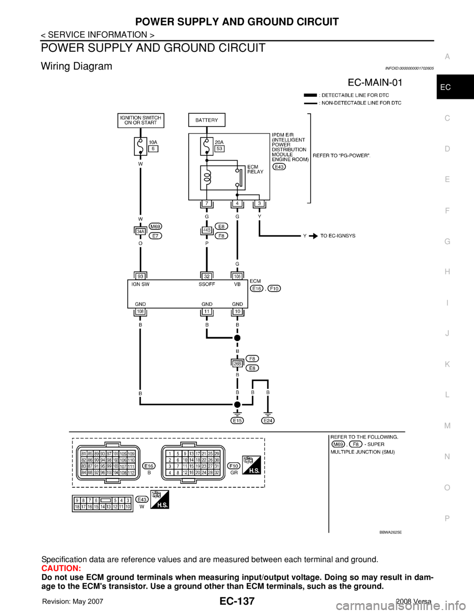
Wiring DiagramINFOID:0000000001702605
Specification data are reference values and are measured between each terminal and ground.
CAUTION:
Do not use ECM ground terminals when measuring input/output voltage. Doing so may result in dam-
age to the ECM's transistor. Use a ground other than ECM terminals, such as the ground.
BBWA2625E
Page 1213 of 2771
POWER SUPPLY AND GROUND CIRCUIT
EC-139
< SERVICE INFORMATION >
C
D
E
F
G
H
I
J
K
L
MA
EC
N
P O
OK or NG
OK >> GO TO 5.
NG >> Repair or replace ground connections.
5.CHECK ECM GROUND CIRCUIT FOR OPEN AND SHORT-I
1. Disconnect ECM harness connector.
2. Check harness continuity between ECM terminals 10, 11, 108 and ground.
Refer to Wiring Diagram.
3. Also check harness for short to power.
OK or NG
OK >> GO TO 7.
NG >> GO TO 6.
6.DETECT MALFUNCTIONING PART
Check the following.
• Harness connectors F8, E8
• Harness for open or short between ECM and ground
>> Repair open circuit or short to power in harness or connectors.
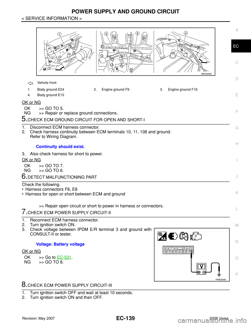
7.CHECK ECM POWER SUPPLY CIRCUIT-II
1. Reconnect ECM harness connector.
2. Turn ignition switch ON.
3. Check voltage between IPDM E/R terminal 3 and ground with
CONSULT-II or tester.
OK or NG
OK >> Go to EC-531.
NG >> GO TO 8.
8.CHECK ECM POWER SUPPLY CIRCUIT-III
1. Turn ignition switch OFF and wait at least 10 seconds.
2. Turn ignition switch ON and then OFF.
:Vehicle front
1. Body ground E24 2. Engine ground F9 3. Engine ground F16
4. Body ground E15
BBIA0698E
Continuity should exist.
Voltage: Battery voltage
PBIB2658E
Page 1214 of 2771
EC-140
< SERVICE INFORMATION >
POWER SUPPLY AND GROUND CIRCUIT
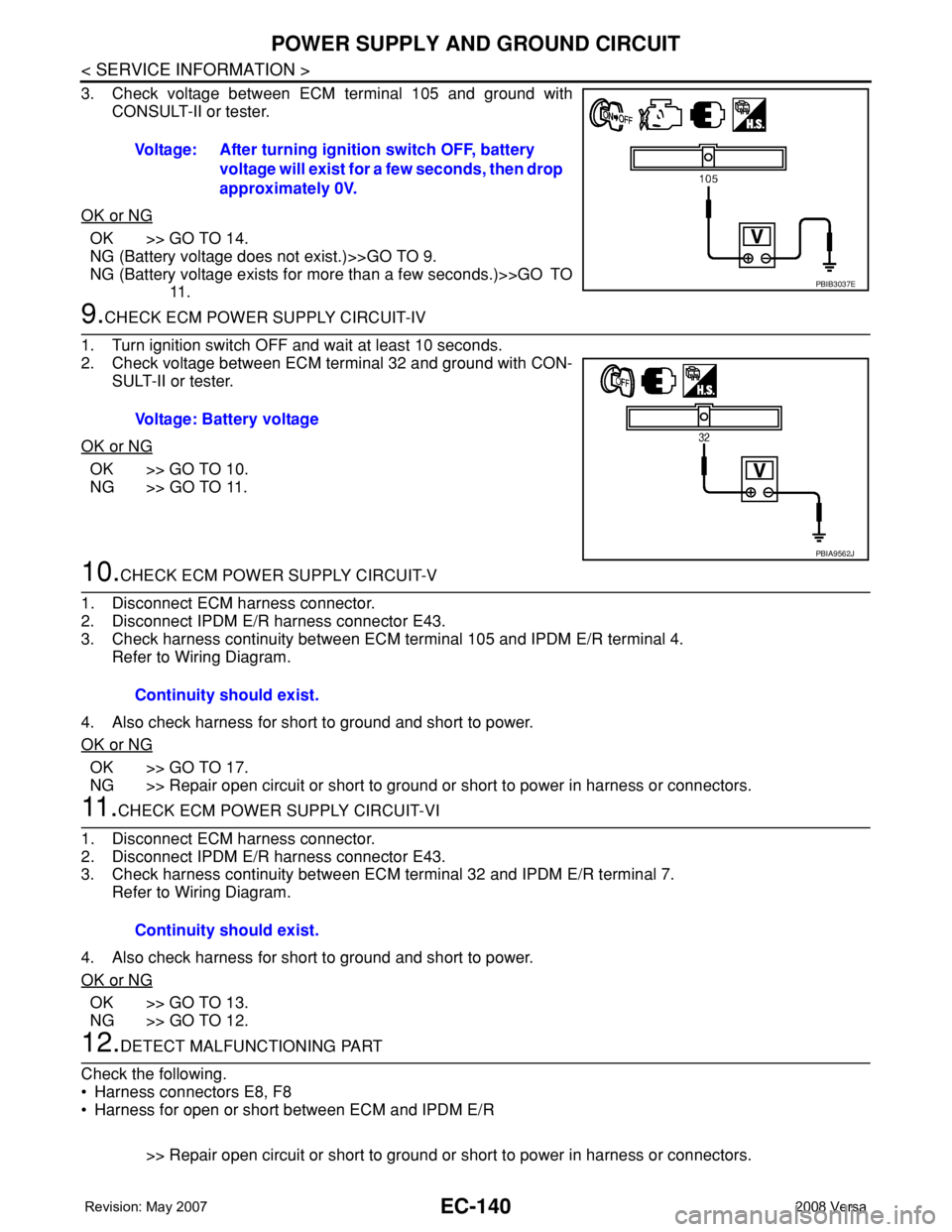
3. Check voltage between ECM terminal 105 and ground with
CONSULT-II or tester.
OK or NG
OK >> GO TO 14.
NG (Battery voltage does not exist.)>>GO TO 9.
NG (Battery voltage exists for more than a few seconds.)>>GO TO
11 .
9.CHECK ECM POWER SUPPLY CIRCUIT-IV
1. Turn ignition switch OFF and wait at least 10 seconds.
2. Check voltage between ECM terminal 32 and ground with CON-
SULT-II or tester.
OK or NG
OK >> GO TO 10.
NG >> GO TO 11.
10.CHECK ECM POWER SUPPLY CIRCUIT-V
1. Disconnect ECM harness connector.
2. Disconnect IPDM E/R harness connector E43.
3. Check harness continuity between ECM terminal 105 and IPDM E/R terminal 4.
Refer to Wiring Diagram.
4. Also check harness for short to ground and short to power.
OK or NG
OK >> GO TO 17.
NG >> Repair open circuit or short to ground or short to power in harness or connectors.
11 .CHECK ECM POWER SUPPLY CIRCUIT-VI
1. Disconnect ECM harness connector.
2. Disconnect IPDM E/R harness connector E43.
3. Check harness continuity between ECM terminal 32 and IPDM E/R terminal 7.
Refer to Wiring Diagram.
4. Also check harness for short to ground and short to power.
OK or NG
OK >> GO TO 13.
NG >> GO TO 12.
12.DETECT MALFUNCTIONING PART
Check the following.
• Harness connectors E8, F8
• Harness for open or short between ECM and IPDM E/R
>> Repair open circuit or short to ground or short to power in harness or connectors. Voltage: After turning ignition switch OFF, battery
voltage will exist for a few seconds, then drop
approximately 0V.
PBIB3037E
Voltage: Battery voltage
PBIA9562J
Continuity should exist.
Continuity should exist.
Page 1215 of 2771
POWER SUPPLY AND GROUND CIRCUIT
EC-141
< SERVICE INFORMATION >
C
D
E
F
G
H
I
J
K
L
MA
EC
N
P O
13.CHECK 20A FUSE
1. Disconnect 20A fuse from IPDM E/R.
2. Check 20A fuse.
OK or NG
OK >> GO TO 17.
NG >> Replace 20A fuse.
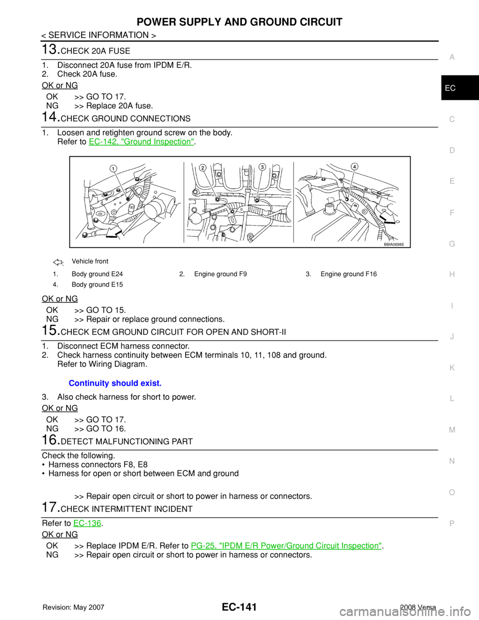
14.CHECK GROUND CONNECTIONS
1. Loosen and retighten ground screw on the body.
Refer to EC-142, "
Ground Inspection".
OK or NG
OK >> GO TO 15.
NG >> Repair or replace ground connections.
15.CHECK ECM GROUND CIRCUIT FOR OPEN AND SHORT-II
1. Disconnect ECM harness connector.
2. Check harness continuity between ECM terminals 10, 11, 108 and ground.
Refer to Wiring Diagram.
3. Also check harness for short to power.
OK or NG
OK >> GO TO 17.
NG >> GO TO 16.
16.DETECT MALFUNCTIONING PART
Check the following.
• Harness connectors F8, E8
• Harness for open or short between ECM and ground
>> Repair open circuit or short to power in harness or connectors.
17.CHECK INTERMITTENT INCIDENT
Refer to EC-136
.
OK or NG
OK >> Replace IPDM E/R. Refer to PG-25, "IPDM E/R Power/Ground Circuit Inspection".
NG >> Repair open circuit or short to power in harness or connectors.
:Vehicle front
1. Body ground E24 2. Engine ground F9 3. Engine ground F16
4. Body ground E15
BBIA0698E
Continuity should exist.
Page 1228 of 2771
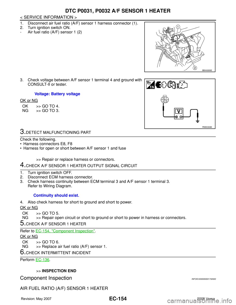
EC-154
< SERVICE INFORMATION >
DTC P0031, P0032 A/F SENSOR 1 HEATER
1. Disconnect air fuel ratio (A/F) sensor 1 harness connector (1).
2. Turn ignition switch ON.
- Air fuel ratio (A/F) sensor 1 (2)
3. Check voltage between A/F sensor 1 terminal 4 and ground with
CONSULT-II or tester.
OK or NG
OK >> GO TO 4.
NG >> GO TO 3.
3.DETECT MALFUNCTIONING PART
Check the following.
• Harness connectors E8, F8
• Harness for open or short between A/F sensor 1 and fuse
>> Repair or replace harness or connectors.
4.CHECK A/F SENSOR 1 HEATER OUTPUT SIGNAL CIRCUIT
1. Turn ignition switch OFF.
2. Disconnect ECM harness connector.
3. Check harness continuity between ECM terminal 3 and A/F sensor 1 terminal 3.
Refer to Wiring Diagram.
4. Also check harness for short to ground and short to power.
OK or NG
OK >> GO TO 5.
NG >> Repair open circuit or short to ground or short to power in harness or connectors.
5.CHECK A/F SENSOR 1 HEATER
Refer to EC-154, "
Component Inspection".
OK or NG
OK >> GO TO 6.
NG >> Replace air fuel ratio (A/F) sensor 1.
6.CHECK INTERMITTENT INCIDENT
Perform EC-136
.
>>INSPECTION END
Component InspectionINFOID:0000000001702630
AIR FUEL RATIO (A/F) SENSOR 1 HEATER
BBIA0699E
Voltage: Battery voltage
PBIB3308E
Continuity should exist.