2008 NISSAN TIIDA VIN
[x] Cancel search: VINPage 22 of 2771
AT-10
< SERVICE INFORMATION >
PREPARATION
PREPARATION
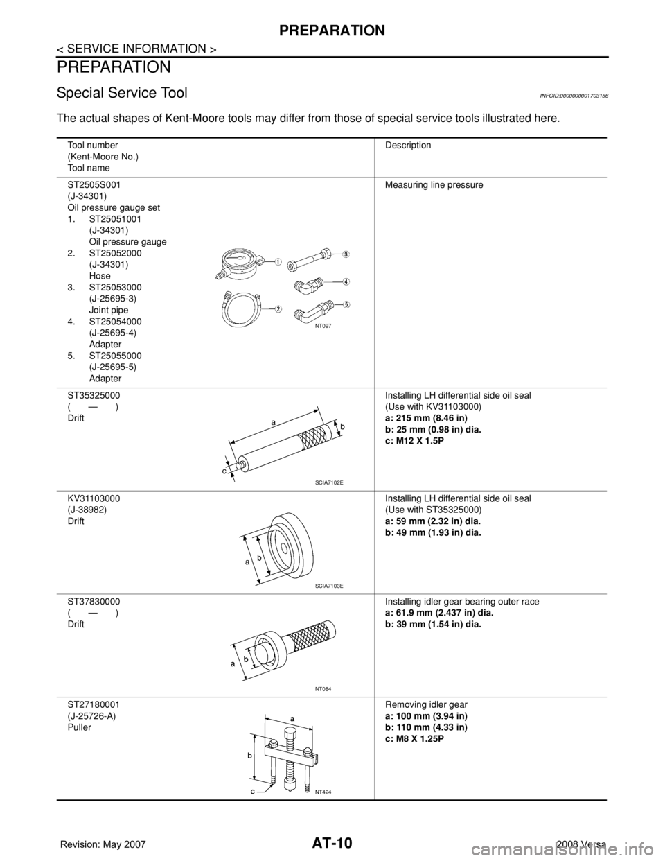
Special Service ToolINFOID:0000000001703156
The actual shapes of Kent-Moore tools may differ from those of special service tools illustrated here.
Tool number
(Kent-Moore No.)
Tool nameDescription
ST2505S001
(J-34301)
Oil pressure gauge set
1. ST25051001
(J-34301)
Oil pressure gauge
2. ST25052000
(J-34301)
Hose
3. ST25053000
(J-25695-3)
Joint pipe
4. ST25054000
(J-25695-4)
Adapter
5. ST25055000
(J-25695-5)
AdapterMeasuring line pressure
ST35325000
( — )
DriftInstalling LH differential side oil seal
(Use with KV31103000)
a: 215 mm (8.46 in)
b: 25 mm (0.98 in) dia.
c: M12 X 1.5P
KV31103000
(J-38982)
DriftInstalling LH differential side oil seal
(Use with ST35325000)
a: 59 mm (2.32 in) dia.
b: 49 mm (1.93 in) dia.
ST37830000
( — )
DriftInstalling idler gear bearing outer race
a: 61.9 mm (2.437 in) dia.
b: 39 mm (1.54 in) dia.
ST27180001
(J-25726-A)
PullerRemoving idler gear
a: 100 mm (3.94 in)
b: 110 mm (4.33 in)
c: M8 X 1.25P
NT097
SCIA7102E
SCIA7103E
NT084
NT424
Page 23 of 2771
PREPARATION
AT-11
< SERVICE INFORMATION >
D
E
F
G
H
I
J
K
L
MA
B
AT
N
O
P
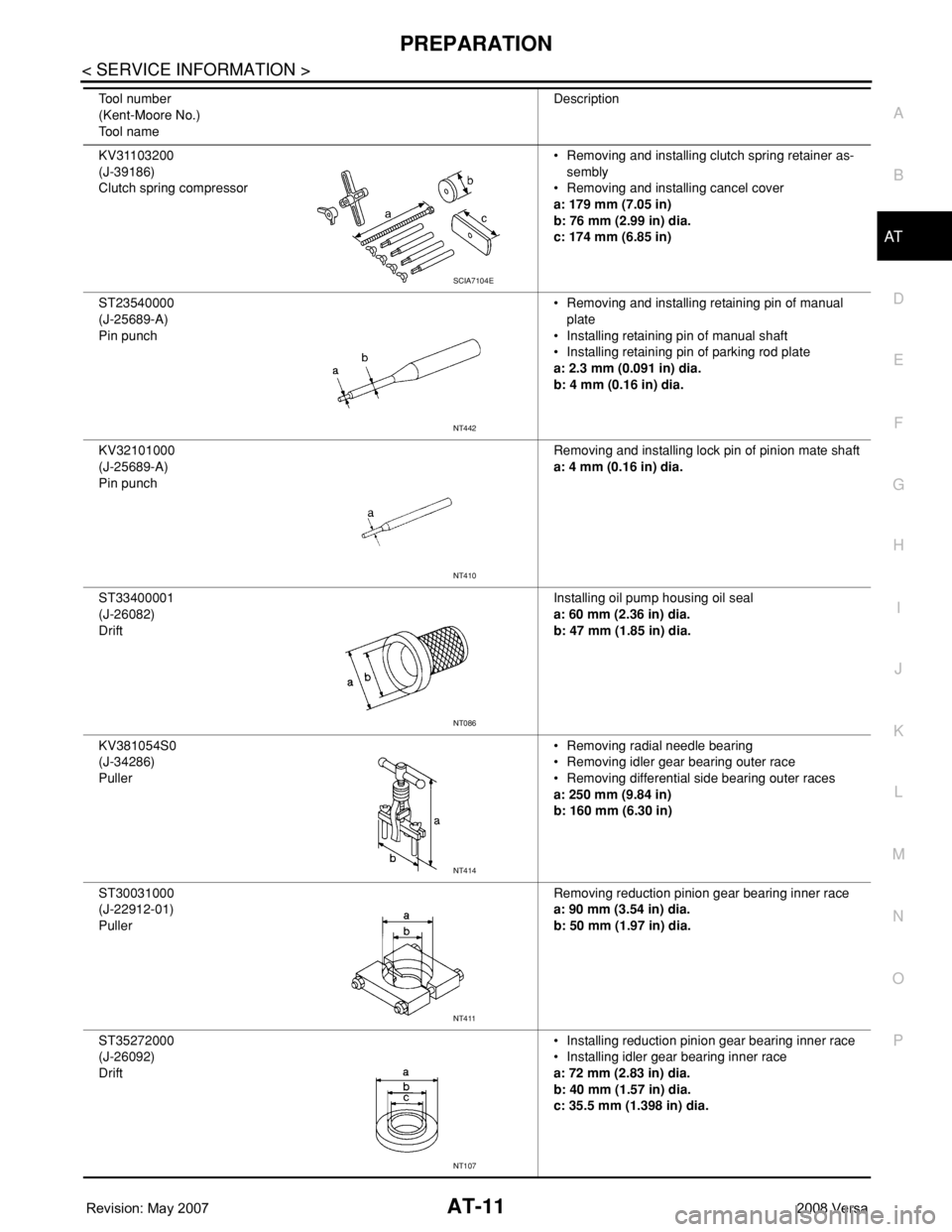
KV31103200
(J-39186)
Clutch spring compressor• Removing and installing clutch spring retainer as-
sembly
• Removing and installing cancel cover
a: 179 mm (7.05 in)
b: 76 mm (2.99 in) dia.
c: 174 mm (6.85 in)
ST23540000
(J-25689-A)
Pin punch• Removing and installing retaining pin of manual
plate
• Installing retaining pin of manual shaft
• Installing retaining pin of parking rod plate
a: 2.3 mm (0.091 in) dia.
b: 4 mm (0.16 in) dia.
KV32101000
(J-25689-A)
Pin punchRemoving and installing lock pin of pinion mate shaft
a: 4 mm (0.16 in) dia.
ST33400001
(J-26082)
DriftInstalling oil pump housing oil seal
a: 60 mm (2.36 in) dia.
b: 47 mm (1.85 in) dia.
KV381054S0
(J-34286)
Puller• Removing radial needle bearing
• Removing idler gear bearing outer race
• Removing differential side bearing outer races
a: 250 mm (9.84 in)
b: 160 mm (6.30 in)
ST30031000
(J-22912-01)
PullerRemoving reduction pinion gear bearing inner race
a: 90 mm (3.54 in) dia.
b: 50 mm (1.97 in) dia.
ST35272000
(J-26092)
Drift• Installing reduction pinion gear bearing inner race
• Installing idler gear bearing inner race
a: 72 mm (2.83 in) dia.
b: 40 mm (1.57 in) dia.
c: 35.5 mm (1.398 in) dia. Tool number
(Kent-Moore No.)
Tool nameDescription
SCIA7104E
NT442
NT410
NT086
NT414
NT411
NT107
Page 25 of 2771
PREPARATION
AT-13
< SERVICE INFORMATION >
D
E
F
G
H
I
J
K
L
MA
B
AT
N
O
P
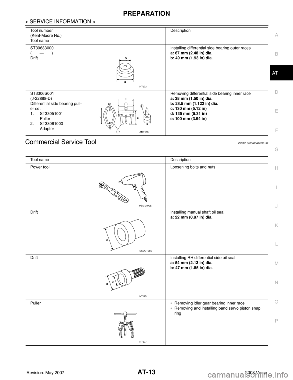
Commercial Service ToolINFOID:0000000001703157
ST30633000
( — )
DriftInstalling differential side bearing outer races
a: 67 mm (2.48 in) dia.
b: 49 mm (1.93 in) dia.
ST3306S001
(J-22888-D)
Differential side bearing pull-
er set
1. ST33051001
Puller
2. ST33061000
AdapterRemoving differential side bearing inner race
a: 38 mm (1.50 in) dia.
b: 28.5 mm (1.122 in) dia.
c: 130 mm (5.12 in)
d: 135 mm (5.31 in)
e: 100 mm (3.94 in) Tool number
(Kent-Moore No.)
Tool nameDescription
NT073
AMT153
Tool name Description
Power tool Loosening bolts and nuts
DriftInstalling manual shaft oil seal
a: 22 mm (0.87 in) dia.
DriftInstalling RH differential side oil seal
a: 54 mm (2.13 in) dia.
b: 47 mm (1.85 in) dia.
Puller• Removing idler gear bearing inner race
• Removing and installing band servo piston snap
ring
PBIC0190E
SCIA7105E
NT115
NT077
Page 26 of 2771
AT-14
< SERVICE INFORMATION >
PREPARATION
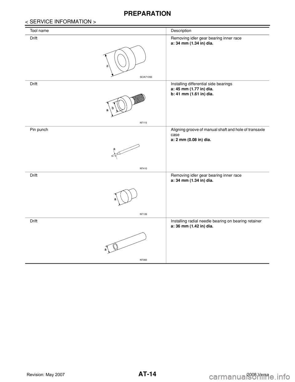
DriftRemoving idler gear bearing inner race
a: 34 mm (1.34 in) dia.
DriftInstalling differential side bearings
a: 45 mm (1.77 in) dia.
b: 41 mm (1.61 in) dia.
Pin punch Aligning groove of manual shaft and hole of transaxle
case
a: 2 mm (0.08 in) dia.
DriftRemoving idler gear bearing inner race
a: 34 mm (1.34 in) dia.
DriftInstalling radial needle bearing on bearing retainer
a: 36 mm (1.42 in) dia. Tool name Description
SCIA7105E
NT115
NT410
NT109
NT083
Page 27 of 2771
A/T FLUID
AT-15
< SERVICE INFORMATION >
D
E
F
G
H
I
J
K
L
MA
B
AT
N
O
P
A/T FLUID
Checking A/T FluidINFOID:0000000001703158
1. Warm up engine.
2. Check for A/T fluid leakage.
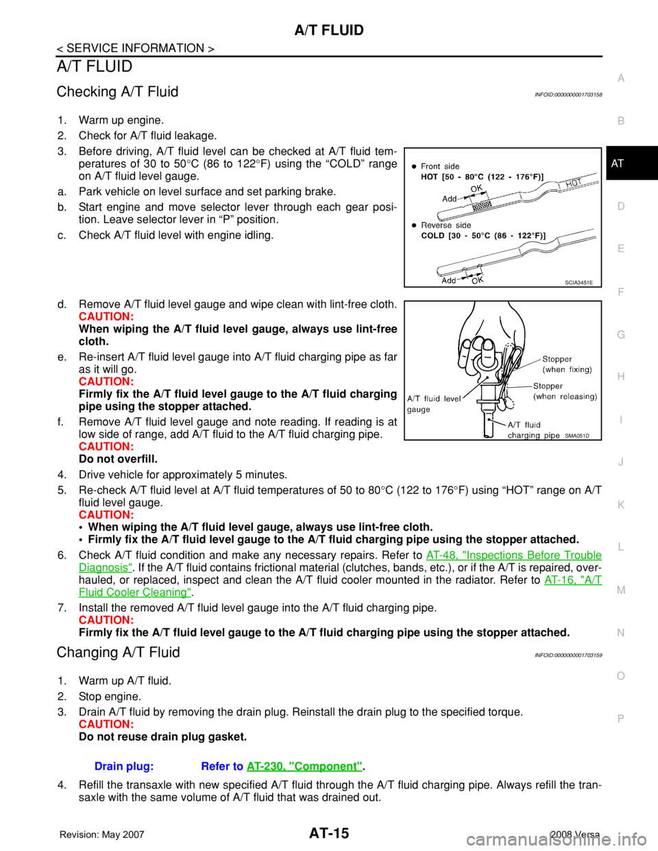
3. Before driving, A/T fluid level can be checked at A/T fluid tem-
peratures of 30 to 50°C (86 to 122°F) using the “COLD” range
on A/T fluid level gauge.
a. Park vehicle on level surface and set parking brake.
b. Start engine and move selector lever through each gear posi-
tion. Leave selector lever in “P” position.
c. Check A/T fluid level with engine idling.
d. Remove A/T fluid level gauge and wipe clean with lint-free cloth.
CAUTION:
When wiping the A/T fluid level gauge, always use lint-free
cloth.
e. Re-insert A/T fluid level gauge into A/T fluid charging pipe as far
as it will go.
CAUTION:
Firmly fix the A/T fluid level gauge to the A/T fluid charging
pipe using the stopper attached.
f. Remove A/T fluid level gauge and note reading. If reading is at
low side of range, add A/T fluid to the A/T fluid charging pipe.
CAUTION:
Do not overfill.
4. Drive vehicle for approximately 5 minutes.
5. Re-check A/T fluid level at A/T fluid temperatures of 50 to 80°C (122 to 176°F) using “HOT” range on A/T
fluid level gauge.
CAUTION:
• When wiping the A/T fluid level gauge, always use lint-free cloth.
• Firmly fix the A/T fluid level gauge to the A/T fluid charging pipe using the stopper attached.
6. Check A/T fluid condition and make any necessary repairs. Refer to AT-48, "
Inspections Before Trouble
Diagnosis". If the A/T fluid contains frictional material (clutches, bands, etc.), or if the A/T is repaired, over-
hauled, or replaced, inspect and clean the A/T fluid cooler mounted in the radiator. Refer to AT-16, "
A/T
Fluid Cooler Cleaning".
7. Install the removed A/T fluid level gauge into the A/T fluid charging pipe.
CAUTION:
Firmly fix the A/T fluid level gauge to the A/T fluid charging pipe using the stopper attached.
Changing A/T FluidINFOID:0000000001703159
1. Warm up A/T fluid.
2. Stop engine.
3. Drain A/T fluid by removing the drain plug. Reinstall the drain plug to the specified torque.
CAUTION:
Do not reuse drain plug gasket.
4. Refill the transaxle with new specified A/T fluid through the A/T fluid charging pipe. Always refill the tran-
saxle with the same volume of A/T fluid that was drained out.
SCIA3451E
SMA051D
Drain plug: Refer to AT-230, "Component".
Page 41 of 2771

A/T CONTROL SYSTEM
AT-29
< SERVICE INFORMATION >
D
E
F
G
H
I
J
K
L
MA
B
AT
N
O
P
*1: Spare for vehicle speed sensor·A/T (revolution sensor)
*2: Spare for accelerator pedal position signal
*3: If these input and output signals are different, the TCM triggers the fail-safe function.
*4: Used as a condition for starting self-diagnostics; if self-diagnosis are not started, it is judged that there is some kind of error.
*5: Input by CAN communications.
*6: Output by CAN communications.
Line Pressure ControlINFOID:0000000001703166
• TCM has various line pressure control characteristics to match the driving conditions.
• An ON-OFF duty signal is sent to the line pressure solenoid valve based on TCM characteristics.
• Hydraulic pressure on the clutch and brake is electronically controlled through the line pressure solenoid
valve to accommodate engine torque. This results in smooth shift operation.
NORMAL CONTROL
The characteristic of the line pressure to the throttle opening is set
for suitable clutch operation.
BACK-UP CONTROL (ENGINE BRAKE)
If the selector lever is shifted to “2” position while driving in D4 or D3,
great driving force is applied to the clutch inside the transaxle. Clutch
operating pressure (line pressure) must be increased to deal with
this driving force.
DURING SHIFT CHANGE
Out-
putShift solenoid valve A/B X (*3) X X
Line pressure solenoid X (*3) X X
Torque converter clutch solenoid
valveX(*3) XX
Overrun clutch solenoid valve X X (*3) X X
OD OFF indicator lamp
(*6)XX Control itemLine
pressure
controlVeh icl e
speed
controlShift
controlLock-up
controlEngine
brake
controlFail-safe
functionSelf-diag-
nostics
function
SAT003J
SAT004J
Page 43 of 2771
A/T CONTROL SYSTEM
AT-31
< SERVICE INFORMATION >
D
E
F
G
H
I
J
K
L
MA
B
AT
N
O
P
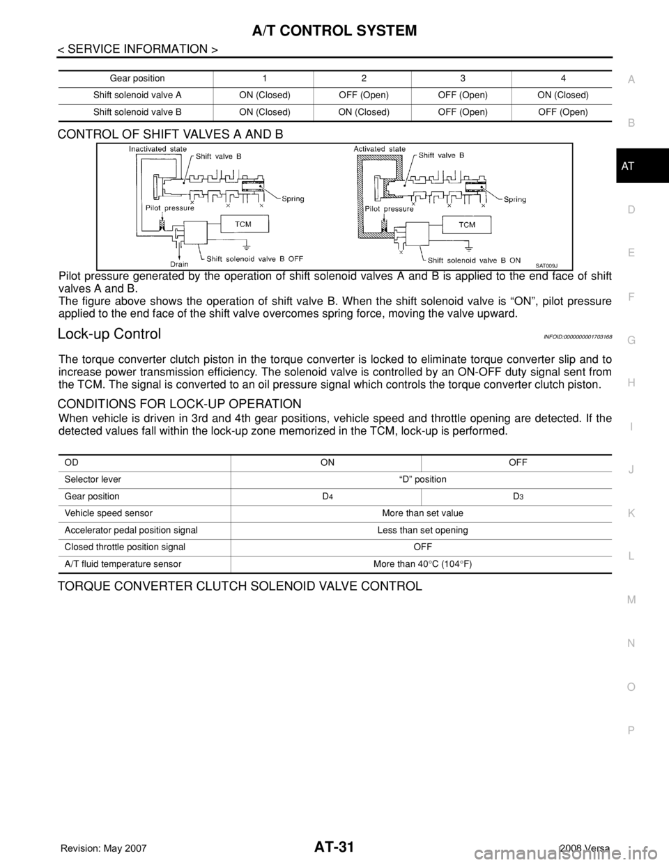
CONTROL OF SHIFT VALVES A AND B
Pilot pressure generated by the operation of shift solenoid valves A and B is applied to the end face of shift
valves A and B.
The figure above shows the operation of shift valve B. When the shift solenoid valve is “ON”, pilot pressure
applied to the end face of the shift valve overcomes spring force, moving the valve upward.
Lock-up ControlINFOID:0000000001703168
The torque converter clutch piston in the torque converter is locked to eliminate torque converter slip and to
increase power transmission efficiency. The solenoid valve is controlled by an ON-OFF duty signal sent from
the TCM. The signal is converted to an oil pressure signal which controls the torque converter clutch piston.
CONDITIONS FOR LOCK-UP OPERATION
When vehicle is driven in 3rd and 4th gear positions, vehicle speed and throttle opening are detected. If the
detected values fall within the lock-up zone memorized in the TCM, lock-up is performed.
TORQUE CONVERTER CLUTCH SOLENOID VALVE CONTROL
Gear position 1 2 3 4
Shift solenoid valve A ON (Closed) OFF (Open) OFF (Open) ON (Closed)
Shift solenoid valve B ON (Closed) ON (Closed) OFF (Open) OFF (Open)
SAT009J
OD ON OFF
Selector lever “D” position
Gear position D
4D3
Vehicle speed sensor More than set value
Accelerator pedal position signal Less than set opening
Closed throttle position signal OFF
A/T fluid temperature sensor More than 40°C (104°F)
Page 45 of 2771

A/T CONTROL SYSTEM
AT-33
< SERVICE INFORMATION >
D
E
F
G
H
I
J
K
L
MA
B
AT
N
O
P
OVERRUN CLUTCH OPERATING CONDITIONS
OVERRUN CLUTCH SOLENOID VALVE CONTROL
The overrun clutch solenoid valve is operated by an ON-OFF signal
transmitted by the TCM to provide overrun clutch control (engine
brake control).
When this solenoid valve is “ON”, the pilot pressure drain port
closes. When it is “OFF”, the drain port opens.
During the solenoid valve “ON” pilot pressure is applied to the end
face of the overrun clutch control valve.
OVERRUN CLUTCH CONTROL VALVE OPERATION
When the solenoid valve is “ON”, pilot pressure is applied to the
overrun clutch control valve. This pushes up the overrun clutch con-
trol valve. The line pressure is then shut off so that the clutch does
not engage. Only in “1” position, however, 1 range pressure is
applied to overrun clutch control valve, resulting in valve moving
downward and clutch engaged.
When the solenoid valve is “OFF”, pilot pressure is not generated. At
this point, the overrun clutch control valve moves downward by
spring force. As a result, overrun clutch operation pressure is pro-
vided by the overrun clutch reducing valve. At overrun clutch reduc-
ing valve in “D” position, the hydraulic pressure is reduced to a level
that balances the spring force. This is sent to overrun clutch control
valve and becomes the operating pressure of overrun clutch which is
engaged at all times. In “2” position and “1” position, overrun clutch
reducing valve is pushed down by 2 range pressure. Line pressure is
directly sent to overrun clutch control valve and becomes the operat-
ing pressure of overrun clutch which is engaged at all times.
SCIA7186E
SAT015J
SCIA7172E