2008 NISSAN TIIDA Rear
[x] Cancel search: RearPage 1 of 2771

-1
QUICK REFERENCE INDEX
AGENERAL INFORMATIONGIGeneral Information
BENGINEEMEngine Mechanical
LUEngine Lubrication System
COEngine Cooling System
ECEngine Control System
FLFuel System
EXExhaust System
ACCAccelerator Control System
CTRANSMISSION/
TRANSAXLECLClutch System
MTManual Transaxle
ATAutomatic Transaxle
CVTCVT
DDRIVELINE/AXLEFAXFront Axle
RAXRear Axle
ESUSPENSIONFSUFront Suspension
RSURear Suspension
WTRoad Wheels & Tires
FBRAKESBRBrake System
PBParking Brake System
BRCBrake Control System
GSTEERINGPSPower Steering System
STCSteering Control System
HRESTRAINTSSBSeat Belts
SRSSupplemental Restraint System (SRS)
IBODYBLBody, Lock & Security System
GWGlasses, Window System & Mirrors
RFRoof
EIExterior & Interior
IPInstrument Panel
SESeat
JAIR CONDITIONERMTCManual Air Conditioner
KELECTRICALSCStarting & Charging System
LTLighting System
DIDriver Information System
WWWiper, Washer & Horn
BCSBody Control System
LANLAN System
AVAudio Visual, Navigation & Telephone System
ACSAuto Cruise Control System
PGPower Supply, Ground & Circuit Elements
LMAINTENANCEMAMaintenance
Edition: May 2007
Revision: May 2007
Publication No. SM8E-1C11U0
B
D
© 2007 NISSAN NORTH AMERICA, INC.
All rights reserved. No part of this Service Manual may be reproduced or stored in a retrieval system, or transmitted in any
form, or by any means, electronic, mechanical, photo-copying, recording or otherwise, without the prior written permission
of Nissan North America Inc.
A
C
E
F
G
H
I
J
K
L
M
Page 5 of 2771

QUICK REFERENCE CHART: VERSA
2008
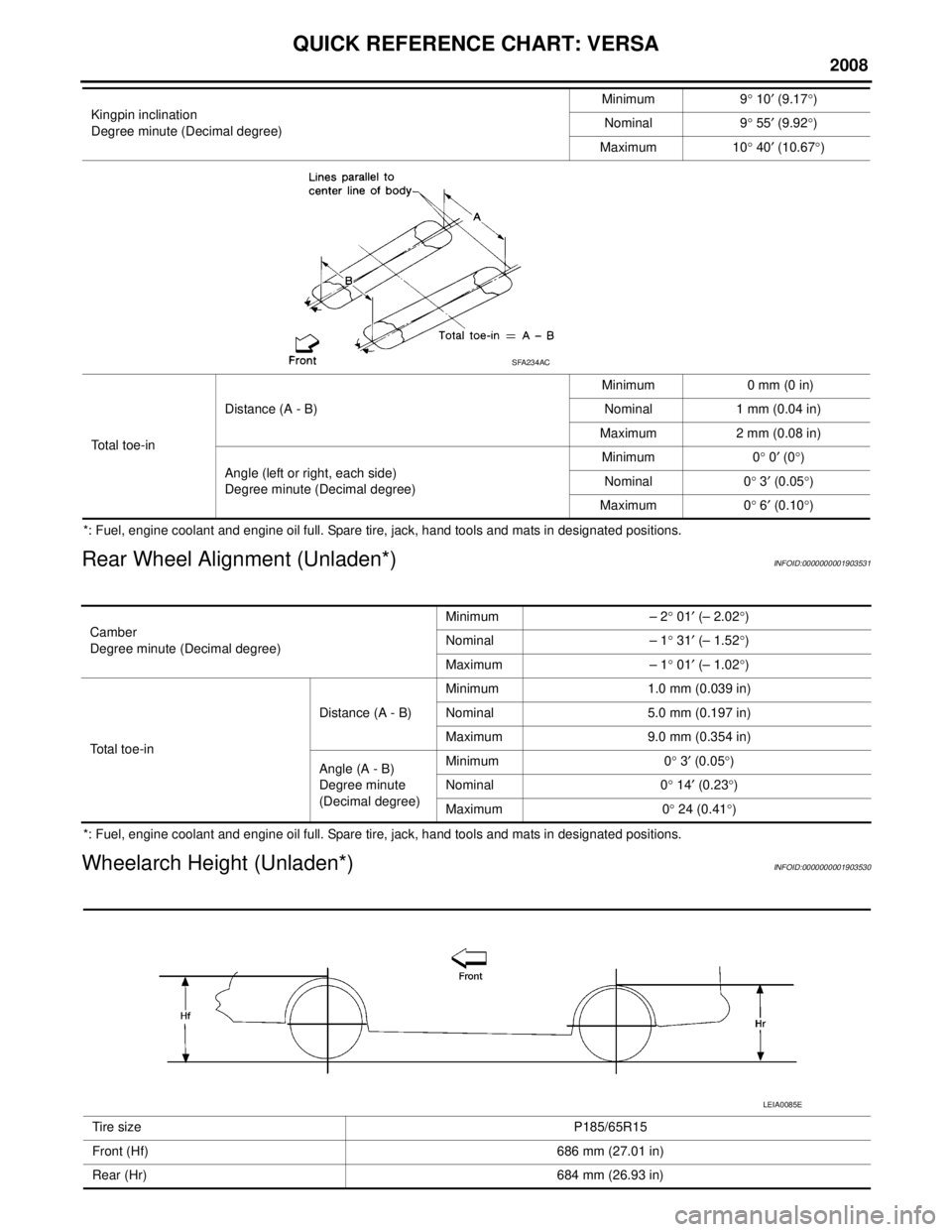
*: Fuel, engine coolant and engine oil full. Spare tire, jack, hand tools and mats in designated positions.
Rear Wheel Alignment (Unladen*)INFOID:0000000001903531
*: Fuel, engine coolant and engine oil full. Spare tire, jack, hand tools and mats in designated positions.
Wheelarch Height (Unladen*)INFOID:0000000001903530
Kingpin inclination
Degree minute (Decimal degree)Minimum 9
° 10 ′ (9.17 °)
Nominal 9 ° 55 ′ (9.92 °)
Maximum 10 ° 40 ′ (10.67 °)
Total toe-in Distance (A - B)
Minimum 0 mm (0 in)
Nominal 1 mm (0.04 in)
Maximum 2 mm (0.08 in)
Angle (left or right, each side)
Degree minute (Decimal degree) Minimum 0
° 0 ′ (0 °)
Nominal 0 ° 3 ′ (0.05 °)
Maximum 0 ° 6 ′ (0.10 °)
SFA234AC
Camber
Degree minute (Decimal degree) Minimum – 2
° 01 ′ (– 2.02 °)
Nominal – 1 ° 31 ′ (– 1.52 °)
Maximum – 1 ° 01 ′ (– 1.02 °)
Total toe-in Distance (A - B)
Minimum 1.0 mm (0.039 in)
Nominal 5.0 mm (0.197 in)
Maximum 9.0 mm (0.354 in)
Angle (A - B)
Degree minute
(Decimal degree) Minimum 0
° 3 ′ (0.05 °)
Nominal 0 ° 14 ′ (0.23 °)
Maximum 0 ° 24 (0.41 °)
Tire size P185/65R15
Front (Hf) 686 mm (27.01 in)
Rear (Hr) 684 mm (26.93 in)
LEIA0085E
Page 6 of 2771

2008
QUICK REFERENCE CHART: VERSA
*: Fuel, engine coolant and engine oil full. Spare tire, jack, hand tools and mats in designated positions.
General SpecificationINFOID:0000000001903532
Brake PedalINFOID:0000000001903533
Unit: mm (in)
Front Disc BrakeINFOID:0000000001903534
Unit: mm (in)
Rear Drum BrakeINFOID:0000000001903535
Unit: mm (in)
Front brake Brake model CLZ25VACylinder bore diameter 57.2 mm (2.252 in)
Pad
Length × width × thickness 125.6 mm
× 46.0 mm × 9.5 mm
(4.945 in × 1.811 in × 0.374 in)
Rotor outer diameter × thickness 280 mm × 24.0 mm (11.02 in × 0.945 in)
Rear brake Brake model LT20D Cylinder bore diameter 15.87 mm (0.625 in)
Lining
Length × width × thickness 194.1 mm
× 30.0 mm × 4.0 mm
(7.642 in × 1.181 in × 0.157 in)
Drum outer diameter 228.6 mm (9.000 in)
Master cylinder Cylinder bore diameter 22.22 mm (0.875 in)
Control valve Valve model Electric brake force distribution
Brake booster Booster model C255 Diaphragm diameter 255 mm (10.04 in)
Brake pedal free height (from dash panel top surface) A/T, CVT model 172.4 - 182.4 (6.79 - 7.18)
M/T model 162.3 - 172.3 (6.39 - 6.78)
Brake pedal depressed height
[under a force of 490 N (50 kg-f, 110 lb-f) with the engine running] A/T, CVT model 98 (3.86) or more
M/T model 90 (3.54) or more
Clearance between brake pedal lever and the threaded end of stop lamp switch 0.74 - 1.96 (0.0291 - 0.0772)
Pedal play 3 - 11 (0.12 - 0.43)
Brake modelCLZ25VA
Brake pad Standard thickness (new) 9.5 (0.374)
Repair limit thickness 2.0 (0.079)
Disc rotor Standard thickness (new) 24.0 (0.945)
Repair limit thickness 22.0 (0.866)
Runout limit 0.04 (0.0016)
Maximum uneven wear (mea-
sured at 8 positions)
0.02 mm (0.0008 in) or less
Brake model
LT 2 0 D
Brake lining Standard thickness (new) 4.0 (0.157)
Repair limit thickness 1.5 (0.059)
Drum Standard inner diameter (new) 228.6 (9.000)
Repair limit inner diameter 230.0 (9.055)
Page 16 of 2771

AT-4
Diagnosis Procedure .............................................210
KEY INTERLOCK CABLE ...............................213
Removal and Installation .......................................213
ON-VEHICLE SERVICE ..................................216
Control Valve Assembly and Accumulators ...........216
Park/Neutral Position (PNP) Switch ......................219
Revolution Sensor .................................................221
Turbine Revolution Sensor (Power Train Revolu-
tion Sensor) ...........................................................
222
Differential Side Oil Seal ........................................223
AIR BREATHER HOSE ...................................225
Removal and Installation .......................................225
TRANSAXLE ASSEMBLY ..............................226
Removal and Installation .......................................226
OVERHAUL .....................................................230
Component ............................................................230
Oil Channel ............................................................237
Location of Adjusting Shims, Needle Bearings and
Thrust Washers .....................................................
238
Location of Snap Rings .........................................239
DISASSEMBLY ...............................................240
Disassembly ..........................................................240
REPAIR FOR COMPONENT PARTS ..............257
Manual Shaft .........................................................257
Oil Pump ................................................................260
Control Valve Assembly ........................................263
Control Valve Upper Body .....................................272
Control Valve Lower Body .....................................276
Reverse Clutch ......................................................279
High Clutch ............................................................284
Forward and Overrun Clutches .............................288
Low & Reverse Brake ............................................295
Rear Internal Gear and Forward Clutch Hub .........299
Output Shaft, Output Gear, Idler Gear, Reduction
Pinion Gear and Bearing Retainer .........................
302
Band Servo Piston Assembly ................................307
Final Drive .............................................................313
ASSEMBLY ......................................................318
Assembly (1) .........................................................318
Adjustment (1) .......................................................319
Assembly (2) .........................................................325
Adjustment (2) .......................................................330
Assembly (3) .........................................................333
SERVICE DATA AND SPECIFICATIONS
(SDS) ................................................................
341
General Specification ............................................341
Vehicle Speed at Which Gear Shifting Occurs .....341
Vehicle Speed at When Lock-up Occurs/Releases
.
341
Stall Speed ............................................................341
Line Pressure ........................................................341
Adjusting shims, Needle Bearings, Thrust Wash-
ers and Snap Rings ..............................................
341
Control Valves .......................................................343
Accumulator ..........................................................343
Clutches and Brakes .............................................343
Final Drive .............................................................345
Planetary Carrier ...................................................345
Oil Pump ...............................................................345
Input Shaft .............................................................345
Reduction Pinion Gear ..........................................345
Band Servo ...........................................................345
Output Shaft ..........................................................346
Bearing Retainer ...................................................346
Total End Play .......................................................346
Reverse Clutch End Play ......................................346
Removal and Installation .......................................346
Shift Solenoid Valves ............................................346
Solenoid Valves ....................................................346
A/T Fluid Temperature Sensor ..............................347
Revolution Sensor .................................................347
Dropping Resistor .................................................347
Turbine Revolution Sensor (Power Train Revolu-
tion Sensor) ...........................................................
347
Page 31 of 2771

A/T CONTROL SYSTEM
AT-19
< SERVICE INFORMATION >
D
E
F
G
H
I
J
K
L
MA
B
AT
N
O
P
A/T CONTROL SYSTEM
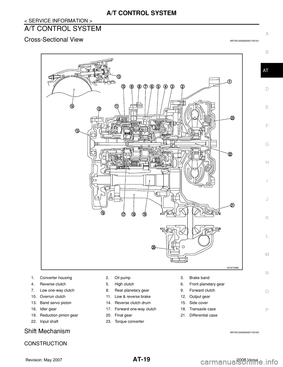
Cross-Sectional ViewINFOID:0000000001703161
Shift MechanismINFOID:0000000001703162
CONSTRUCTION
1. Converter housing 2. Oil pump 3. Brake band
4. Reverse clutch 5. High clutch 6. Front planetary gear
7. Low one-way clutch 8. Rear planetary gear 9. Forward clutch
10. Overrun clutch 11. Low & reverse brake 12. Output gear
13. Band servo piston 14. Reverse clutch drum 15. Side cover
16. Idler gear 17. Forward one-way clutch 18. Transaxle case
19. Reduction pinion gear 20. Final gear 21. Differential case
22. Input shaft 23. Torque converter
SCIA7938E
Page 32 of 2771

AT-20
< SERVICE INFORMATION >
A/T CONTROL SYSTEM
FUNCTION OF CLUTCH AND BRAKE
CLUTCH AND BAND CHART
1. Torque converter 2. Oil pump 3. Input shaft
4. Brake band 5. Reverse clutch 6. High clutch
7. Front sun gear 8. Front pinion gear 9. Front internal gear
10. Front planetary carrier 11. Rear sun gear 12. Rear pinion gear
13. Rear internal gear 14. Rear planetary carrier 15. Forward clutch
16. Forward one-way clutch 17. Overrun clutch 18. Low one-way clutch
19. Low & reverse brake 20. Parking pawl 21. Parking gear
22. Output shaft 23. Idle gear 24. Output gear
SAT998I
Clutch and brake components Abbr. Function
5Reverse clutch R/C To transmit input power to front sun gear 7.
6High clutch H/C To transmit input power to front planetary carrier 10.
15Forward clutch F/C To connect front planetary carrier 10 with forward one-way clutch 16.
17Overrun clutch O/C To connect front planetary carrier 10 with rear internal gear 13.
4Brake band B/B To lock front sun gear 7.
16Forward one-way clutch F/O.CWhen forward clutch 15 is engaged, to stop rear internal gear 13 from rotating in
opposite direction against engine revolution.
18Low one-way clutch L/O.CTo stop front planetary carrier 10 from rotating in opposite direction against en-
gine revolution.
19Low & reverse brake L & R/B To lock front planetary carrier 10.
Shift posi-
tionR/C
5H/C
6F/C
15O/C
17Band servo
F/O.C
16L/O.C
18L&R/B
19Lock-
upRemarks
2nd
apply3rd re-
lease4th ap-
ply
PPA R K
POSITION
RREVERSE
POSITION
NNEUTRAL
POSITION
D*4 1st *1D B B
Page 34 of 2771

AT-22
< SERVICE INFORMATION >
A/T CONTROL SYSTEM
“D1” and “21” Positions
*: Overrun clutch remains in engaged condition when throttle opening is less than 1/16.•Forward clutch
•Forward one-way clutch
•Overrun clutch
•Low & reverse brakeAs overrun clutch engages, rear internal gear is locked by the operation of low and re-
verse brake.
This is different from that of D
1 and 21.
Engine brake Overrun clutch always engages, therefore engine brake can be obtained when deceler-
ating.
SCIA1816E
•Forward one-way clutch
•Forward clutch
•Low one-way clutchRear internal gear is locked to rotate counterclockwise because of the functioning of these three
clutches.
Overrun clutch
engagement conditions
(Engine brake)D
1: OD OFF (OD OFF indicator lamp is on) and throttle opening is less than specification*
2
1: Always engaged
At D
1 and 21 positions, engine brake is not activated due to free turning of low one- way clutch.
Page 35 of 2771

A/T CONTROL SYSTEM
AT-23
< SERVICE INFORMATION >
D
E
F
G
H
I
J
K
L
MA
B
AT
N
O
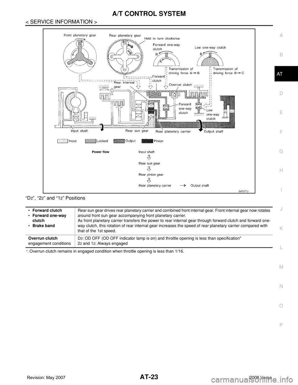
P “D
2”, “22” and “12” Positions
*: Overrun clutch remains in engaged condition when throttle opening is less than 1/16.
SAT377J
•Forward clutch
•Forward one-way
clutch
•Brake bandRear sun gear drives rear planetary carrier and combined front internal gear. Front internal gear now rotates
around front sun gear accompanying front planetary carrier.
As front planetary carrier transfers the power to rear internal gear through forward clutch and forward one-
way clutch, this rotation of rear internal gear increases the speed of rear planetary carrier compared with
that of the 1st speed.
Overrun clutch
engagement conditionsD
2: OD OFF (OD OFF indicator lamp is on) and throttle opening is less than specification*
2
2 and 12: Always engaged