2008 NISSAN TIIDA Electrical
[x] Cancel search: ElectricalPage 1022 of 2771

DI-1
ELECTRICAL
C
D
E
F
G
H
I
J
L
M
SECTION DI
A
B
DI
N
O
P
CONTENTS
DRIVER INFORMATION SYSTEM
SERVICE INFORMATION ............................2
PRECAUTION .....................................................2
Precaution for Supplemental Restraint System
(SRS) "AIR BAG" and "SEAT BELT PRE-TEN-
SIONER" ...................................................................
2
PREPARATION ...................................................3
Commercial Service Tool ..........................................3
COMBINATION METERS ...................................4
Component Parts and Harness Connector Loca-
tion ............................................................................
4
System Description ...................................................4
Arrangement of Combination Meter ..........................6
Internal Circuit ...........................................................7
Wiring Diagram - METER - .......................................8
Combination Meter Harness Connector Terminal
Layout .....................................................................
10
Terminal and Reference Value for Combination
Meter .......................................................................
10
Self-Diagnosis Mode of Combination Meter ............11
CONSULT-III Function (METER/M&A) ...................13
Trouble Diagnosis ...................................................14
Symptom Chart .......................................................15
Power Supply and Ground Circuit Inspection .........15
Vehicle Speed Signal Inspection .............................16
Engine Speed Signal Inspection .............................17
Fuel Level Sensor Signal Inspection .......................17
Fuel Gauge Fluctuates, Indicates Wrong Value, or
Varies ......................................................................
19
Fuel Gauge Does Not Move to Full-position ...........19
DTC [U1000] CAN Communication Circuit .............19
Electrical Component Inspection .............................19
Removal and Installation .........................................20
WARNING LAMPS .............................................21
Schematic ................................................................21
Wiring Diagram - WARN - .......................................22
Oil Pressure Warning Lamp Stays Off (Ignition
Switch ON) ..............................................................
30
Oil Pressure Warning Lamp Does Not Turn Off
(Oil Pressure Is Normal) ..........................................
32
Component Inspection .............................................32
A/T INDICATOR ................................................34
System Description ..................................................34
Wiring Diagram - AT/IND - .......................................35
A/T Indicator Does Not Illuminate ............................36
CVT INDICATOR ...............................................38
System Description ..................................................38
Wiring Diagram - CVTIND - .....................................38
CVT Indicator Does Not Illuminate ..........................39
WARNING CHIME .............................................41
Component Parts and Harness Connector Loca-
tion ...........................................................................
41
System Description ..................................................41
Wiring Diagram - CHIME - .......................................44
Terminal and Reference Value for BCM ..................45
CONSULT-III Function (BCM) .................................45
Trouble Diagnosis ....................................................46
Combination Meter Buzzer Circuit Inspection .........47
Front Door Switch LH Signal Inspection ..................48
Key Switch Signal Inspection (Without Intelligent
Key) .........................................................................
49
Key Switch and Ignition Knob Switch Signal In-
spection (With Intelligent Key, When Mechanical
Key Is Used) ............................................................
50
Lighting Switch Signal Inspection ............................52
Parking Brake Switch Signal Inspection ..................52
Electrical Component Inspection .............................53
Page 1023 of 2771

DI-2
< SERVICE INFORMATION >
PRECAUTION
SERVICE INFORMATION
PRECAUTION
Precaution for Supplemental Restraint System (SRS) "AIR BAG" and "SEAT BELT
PRE-TENSIONER"
INFOID:0000000001704488
The Supplemental Restraint System such as “AIR BAG” and “SEAT BELT PRE-TENSIONER”, used along
with a front seat belt, helps to reduce the risk or severity of injury to the driver and front passenger for certain
types of collision. This system includes seat belt switch inputs and dual stage front air bag modules. The SRS
system uses the seat belt switches to determine the front air bag deployment, and may only deploy one front
air bag, depending on the severity of a collision and whether the front occupants are belted or unbelted.
Information necessary to service the system safely is included in the SR and SB section of this Service Man-
ual.
WARNING:
• To avoid rendering the SRS inoperative, which could increase the risk of personal injury or death in
the event of a collision which would result in air bag inflation, all maintenance must be performed by
an authorized NISSAN/INFINITI dealer.
• Improper maintenance, including incorrect removal and installation of the SRS, can lead to personal
injury caused by unintentional activation of the system. For removal of Spiral Cable and Air Bag
Module, see the SR section.
• Do not use electrical test equipment on any circuit related to the SRS unless instructed to in this
Service Manual. SRS wiring harnesses can be identified by yellow and/or orange harnesses or har-
ness connectors.
Page 1031 of 2771
DI-10
< SERVICE INFORMATION >
COMBINATION METERS
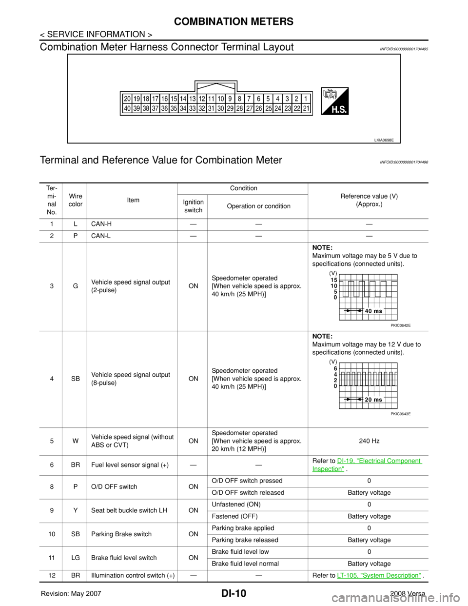
Combination Meter Harness Connector Terminal Layout
INFOID:0000000001704495
Terminal and Reference Value for Combination MeterINFOID:0000000001704496
LKIA0698E
Te r -
mi-
nal
No.Wire
colorItemCondition
Reference value (V)
(Approx.) Ignition
switchOperation or condition
1LCAN-H — — —
2PCAN-L — — —
3GVehicle speed signal output
(2-pulse)ONSpeedometer operated
[When vehicle speed is approx.
40 km/h (25 MPH)] NOTE:
Maximum voltage may be 5 V due to
specifications (connected units).
4SBVehicle speed signal output
(8-pulse)ONSpeedometer operated
[When vehicle speed is approx.
40 km/h (25 MPH)]NOTE:
Maximum voltage may be 12 V due to
specifications (connected units).
5WVehicle speed signal (without
ABS or CVT)ONSpeedometer operated
[When vehicle speed is approx.
20 km/h (12 MPH)]240 Hz
6 BR Fuel level sensor signal (+) — —Refer to DI-19, "
Electrical Component
Inspection" .
8 P O/D OFF switch ONO/D OFF switch pressed 0
O/D OFF switch released Battery voltage
9 Y Seat belt buckle switch LH ONUnfastened (ON) 0
Fastened (OFF) Battery voltage
10 SB Parking Brake switch ONParking brake applied 0
Parking brake released Battery voltage
11 LG Brake fluid level switch ONBrake fluid level low 0
Brake fluid level normal Battery voltage
12 BR Illumination control switch (+) — — Refer to LT- 1 0 5 , "
System Description" .
PKIC0642E
PKIC0643E
Page 1039 of 2771
DI-18
< SERVICE INFORMATION >
COMBINATION METERS
OK or NG
OK >> GO TO 2.
NG >> Replace combination meter. Refer to IP-11, "
Removal and Installation" .
2.CHECK HARNESS CONNECTOR
1. Turn ignition switch OFF.
2. Check combination meter and fuel level sensor unit terminals (meter-side and harness-side) for poor con-
nection.
OK or NG
OK >> GO TO 3.
NG >> Repair or replace terminals or connectors.
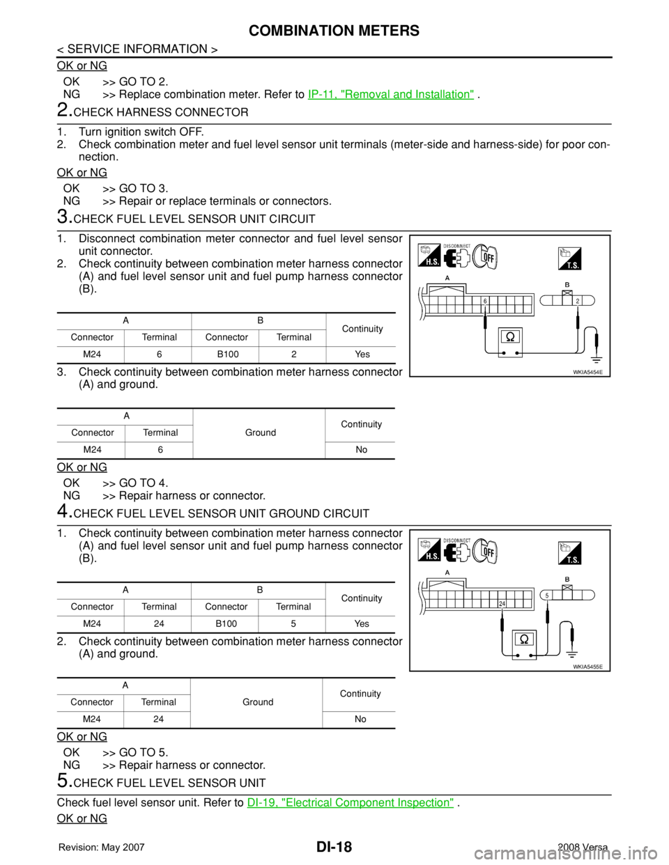
3.CHECK FUEL LEVEL SENSOR UNIT CIRCUIT
1. Disconnect combination meter connector and fuel level sensor
unit connector.
2. Check continuity between combination meter harness connector
(A) and fuel level sensor unit and fuel pump harness connector
(B).
3. Check continuity between combination meter harness connector
(A) and ground.
OK or NG
OK >> GO TO 4.
NG >> Repair harness or connector.
4.CHECK FUEL LEVEL SENSOR UNIT GROUND CIRCUIT
1. Check continuity between combination meter harness connector
(A) and fuel level sensor unit and fuel pump harness connector
(B).
2. Check continuity between combination meter harness connector
(A) and ground.
OK or NG
OK >> GO TO 5.
NG >> Repair harness or connector.
5.CHECK FUEL LEVEL SENSOR UNIT
Check fuel level sensor unit. Refer to DI-19, "
Electrical Component Inspection" .
OK or NG
AB
Continuity
Connector Terminal Connector Terminal
M24 6 B100 2 Yes
A
GroundContinuity
Connector Terminal
M24 6 No
WKIA5454E
AB
Continuity
Connector Terminal Connector Terminal
M24 24 B100 5 Yes
A
GroundContinuity
Connector Terminal
M24 24 No
WKIA5455E
Page 1040 of 2771
COMBINATION METERS
DI-19
< SERVICE INFORMATION >
C
D
E
F
G
H
I
J
L
MA
B
DI
N
O
P
OK >> Check fuel level sensor unit installation, and check whether the float arm interferes or binds with
any of the internal components in the fuel tank. Repair or replace malfunctioning part, if neces-
sary.
NG >> Replace fuel level sensor unit.
Fuel Gauge Fluctuates, Indicates Wrong Value, or VariesINFOID:0000000001704505
1.CHECK FUEL GAUGE FLUCTUATION
Test drive vehicle to see if gauge fluctuates only during driving or at the instant of stopping.
Does the indication value vary only during driving or at the at the instant of stopping?
YES >> The pointer fluctuation may be caused by fuel level change in the fuel tank. Condition is normal.
NO >> Ask the customer about the situation when the symptom occurs in detail, and perform the trouble
diagnosis.
Fuel Gauge Does Not Move to Full-positionINFOID:0000000001704506
1.OBSERVE FUEL GAUGE
Does it take a long time for the pointer to move to FULL position?
YES or NO
YES >> GO TO 2.
NO >> GO TO 3.
2.IDENTIFY FUELING CONDITION
Was the vehicle fueled with the ignition switch ON?
YES or NO
YES >> Be sure to fuel the vehicle with the ignition switch OFF. Otherwise, it will take a long time to move
to FULL position because of the characteristic of the fuel gauge.
NO >> GO TO 3.
3.OBSERVE VEHICLE POSITION
Is the vehicle parked on an incline?
YES or NO
YES >> Check the fuel level indication with vehicle on a level surface.
NO >> GO TO 4.
4.OBSERVE FUEL GAUGE POINTER
During driving, does the fuel gauge pointer move gradually toward EMPTY position?
YES or NO
YES >> Check the components. Refer to DI-19, "Electrical Component Inspection" .
NO >> The float arm may interfere or bind with any of the components in the fuel tank.
DTC [U1000] CAN Communication CircuitINFOID:0000000001704507
Symptom: Display CAN COMM CIRC [U1000] at the result of self-diagnosis for combination meter.
1.CHECK CAN COMMUNICATION
1. Select "SELF-DIAG RESULTS" mode for "METER/M&A" with CONSULT-III.
2. Print out CONSULT-III screen.
>> Go to "CAN SYSTEM". Refer to LAN-15, "
Trouble Diagnosis Flow Chart".
Electrical Component InspectionINFOID:0000000001704508
FUEL LEVEL SENSOR UNIT CHECK
For removal, refer to FL-5, "Removal and Installation" .
Check Fuel Level Sensor Unit and Fuel Pump
Page 1067 of 2771
![NISSAN TIIDA 2008 Service Repair Manual DI-46
< SERVICE INFORMATION >
WARNING CHIME
DATA MONITOR
Display Item List
ACTIVE TEST
Display Item List
SELF-DIAG RESULTS
Display Item List
NOTE:
If “CAN communication [U1000]” is indicated, afte NISSAN TIIDA 2008 Service Repair Manual DI-46
< SERVICE INFORMATION >
WARNING CHIME
DATA MONITOR
Display Item List
ACTIVE TEST
Display Item List
SELF-DIAG RESULTS
Display Item List
NOTE:
If “CAN communication [U1000]” is indicated, afte](/manual-img/5/57399/w960_57399-1066.png)
DI-46
< SERVICE INFORMATION >
WARNING CHIME
DATA MONITOR
Display Item List
ACTIVE TEST
Display Item List
SELF-DIAG RESULTS
Display Item List
NOTE:
If “CAN communication [U1000]” is indicated, after printing the monitor item, go to “LAN system”. Refer to
LAN-15, "
Trouble Diagnosis Flow Chart".
Trouble DiagnosisINFOID:0000000001704526
HOW TO PERFORM TROUBLE DIAGNOSIS
1. Confirm the symptom and customer complaint.
2. Understand the outline of system. Refer to DI-41, "
System Description".
3. Perform the preliminary inspection. Refer to "PRELIMINARY INSPECTION".
4. According to symptom chart, repair or replace the cause of the malfunction. Refer to "SYMPTOM
CHART".
5. Does warning chime system operate normally? If it operates normally, GO TO 6. If not, GO TO 4.
6. Inspection End.
PRELIMINARY INSPECTION
BCM diagnostic
test itemDiagnostic mode Description
Inspection by partWORK SUPPORTSupports inspections and adjustments. Commands are transmitted to the BCM for
setting the status suitable for required operation, input/output signals are received
from the BCM and received data is displayed.
DATA MONITOR Displays BCM input/output data in real time.
ACTIVE TEST Operation of electrical loads can be checked by sending drive signal to them.
SELF-DIAG RESULTS Displays BCM self-diagnosis results.
CAN DIAG SUPPORT MNTR The result of transmit/receive diagnosis of CAN communication can be read.
ECU PART NUMBER BCM part number can be read.
CONFIGURATION Performs BCM configuration read/write functions.
Monitored item ALL SIGNALSSELECTION
FROM MENUContents
IGN ON SW X X Indicates [ON/OFF] condition of ignition switch.
KEY ON SW X X Indicates [ON/OFF] condition of key switch.
DOOR SW-DR X X Indicates [ON/OFF] condition of front door switch LH.
LIGHT SW 1ST X X Indicates [ON/OFF] condition of lighting switch.
BUCKLE SW X X Indicates [ON/OFF] condition of seat belt buckle switch LH.
Test item Malfunction is detected when···
IGN KEY WARN ALM This test is able to check key warning chime operation.
LIGHT WARN ALM This test is able to check light warning chime operation.
SEAT BELT WARN TEST This test is able to check seat belt warning chime operation.
Display item [Code] Malfunction is detected when...
CAN communication [U1000] Malfunction is detected in CAN communication.
Page 1069 of 2771
DI-48
< SERVICE INFORMATION >
WARNING CHIME
OK >> Check battery power supply circuit of combination meter. If OK, replace combination meter. Refer
to IP-11, "
Removal and Installation".
NG >> Replace BCM. Refer to BCS-18, "
Removal and Installation of BCM".
Front Door Switch LH Signal InspectionINFOID:0000000001704528
1.CHECK BCM INPUT SIGNAL
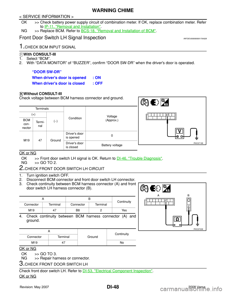
With CONSULT-III
1. Select “BCM”.
2. With “DATA MONITOR” of “BUZZER”, confirm “DOOR SW-DR” when the driver's door is operated.
Without CONSULT-III
Check voltage between BCM harness connector and ground.
OK or NG
OK >> Front door switch LH signal is OK. Return to DI-46, "Trouble Diagnosis".
NG >> GO TO 2.
2.CHECK FRONT DOOR SWITCH LH CIRCUIT
1. Turn ignition switch OFF.
2. Disconnect BCM connector and front door switch LH connector.
3. Check continuity between BCM harness connector (A) and front
door switch LH harness connector (B).
4. Check continuity between BCM harness connector (A) and
ground.
OK or NG
OK >> GO TO 3.
NG >> Repair harness or connector.
3.CHECK FRONT DOOR SWITCH LH
Check front door switch LH. Refer to DI-53, "
Electrical Component Inspection".
OK or NG
“DOOR SW-DR”
When driver's door is opened : ON
When driver's door is closed : OFF
Te r m i n a l s
ConditionVol tag e
(Approx.) (+)
(−) BCM
con-
nectorTe r m i -
nal
M19 47 GroundDriver's door
is opened0
Driver's door
is closedBattery voltage
PKIC0719E
AB
Continuity
Connector Terminal Connector Terminal
M19 47 B8 2 Yes
A
GroundContinuity
Connector Terminal
M19 47 No
PKIC0720E
Page 1074 of 2771
WARNING CHIME
DI-53
< SERVICE INFORMATION >
C
D
E
F
G
H
I
J
L
MA
B
DI
N
O
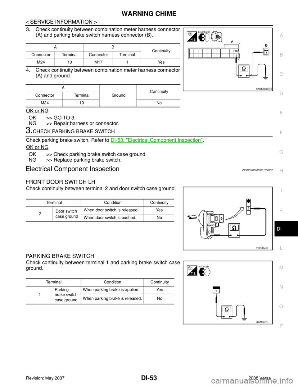
P
3. Check continuity between combination meter harness connector
(A) and parking brake switch harness connector (B).
4. Check continuity between combination meter harness connector
(A) and ground.
OK or NG
OK >> GO TO 3.
NG >> Repair harness or connector.
3.CHECK PARKING BRAKE SWITCH
Check parking brake switch. Refer to DI-53, "
Electrical Component Inspection".
OK or NG
OK >> Check parking brake switch case ground.
NG >> Replace parking brake switch.
Electrical Component InspectionINFOID:0000000001704532
FRONT DOOR SWITCH LH
Check continuity between terminal 2 and door switch case ground.
PARKING BRAKE SWITCH
Check continuity between terminal 1 and parking brake switch case
ground.
AB
Continuity
Connector Terminal Connector Terminal
M2410M17 1 Yes
A
GroundContinuity
Connector Terminal
M24 10 No
AWMIA0067GB
Terminal Condition Continuity
2Door switch
case groundWhen door switch is released. Yes
When door switch is pushed. No
PKIC0245E
Terminal Condition Continuity
1Parking
brake switch
case groundWhen parking brake is applied. Yes
When parking brake is released. No
LKIA0907E