2008 NISSAN TIIDA Electrical
[x] Cancel search: ElectricalPage 1275 of 2771
DTC P0127 IAT SENSOR
EC-201
< SERVICE INFORMATION >
C
D
E
F
G
H
I
J
K
L
MA
EC
N
P O
DTC P0127 IAT SENSOR
Component DescriptionINFOID:0000000001702693
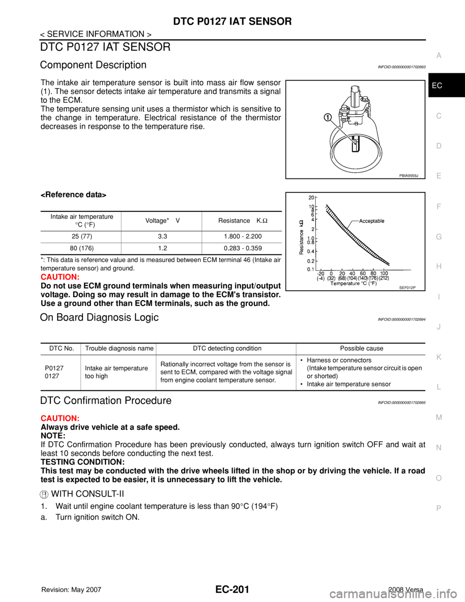
The intake air temperature sensor is built into mass air flow sensor
(1). The sensor detects intake air temperature and transmits a signal
to the ECM.
The temperature sensing unit uses a thermistor which is sensitive to
the change in temperature. Electrical resistance of the thermistor
decreases in response to the temperature rise.
*: This data is reference value and is measured between ECM terminal 46 (Intake air
temperature sensor) and ground.
CAUTION:
Do not use ECM ground terminals when measuring input/output
voltage. Doing so may result in damage to the ECM's transistor.
Use a ground other than ECM terminals, such as the ground.
On Board Diagnosis LogicINFOID:0000000001702694
DTC Confirmation ProcedureINFOID:0000000001702695
CAUTION:
Always drive vehicle at a safe speed.
NOTE:
If DTC Confirmation Procedure has been previously conducted, always turn ignition switch OFF and wait at
least 10 seconds before conducting the next test.
TESTING CONDITION:
This test may be conducted with the drive wheels lifted in the shop or by driving the vehicle. If a road
test is expected to be easier, it is unnecessary to lift the vehicle.
WITH CONSULT-II
1. Wait until engine coolant temperature is less than 90°C (194°F)
a. Turn ignition switch ON.
PBIA9559J
Intake air temperature
°C (°F)Voltage* V Resistance K.Ω
25 (77) 3.3 1.800 - 2.200
80 (176) 1.2 0.283 - 0.359
SEF012P
DTC No. Trouble diagnosis name DTC detecting condition Possible cause
P0127
0127Intake air temperature
too highRationally incorrect voltage from the sensor is
sent to ECM, compared with the voltage signal
from engine coolant temperature sensor.• Harness or connectors
(Intake temperature sensor circuit is open
or shorted)
• Intake air temperature sensor
Page 1344 of 2771
EC-270
< SERVICE INFORMATION >
DTC P0181 FTT SENSOR
DTC P0181 FTT SENSOR
Component DescriptionINFOID:0000000001702768
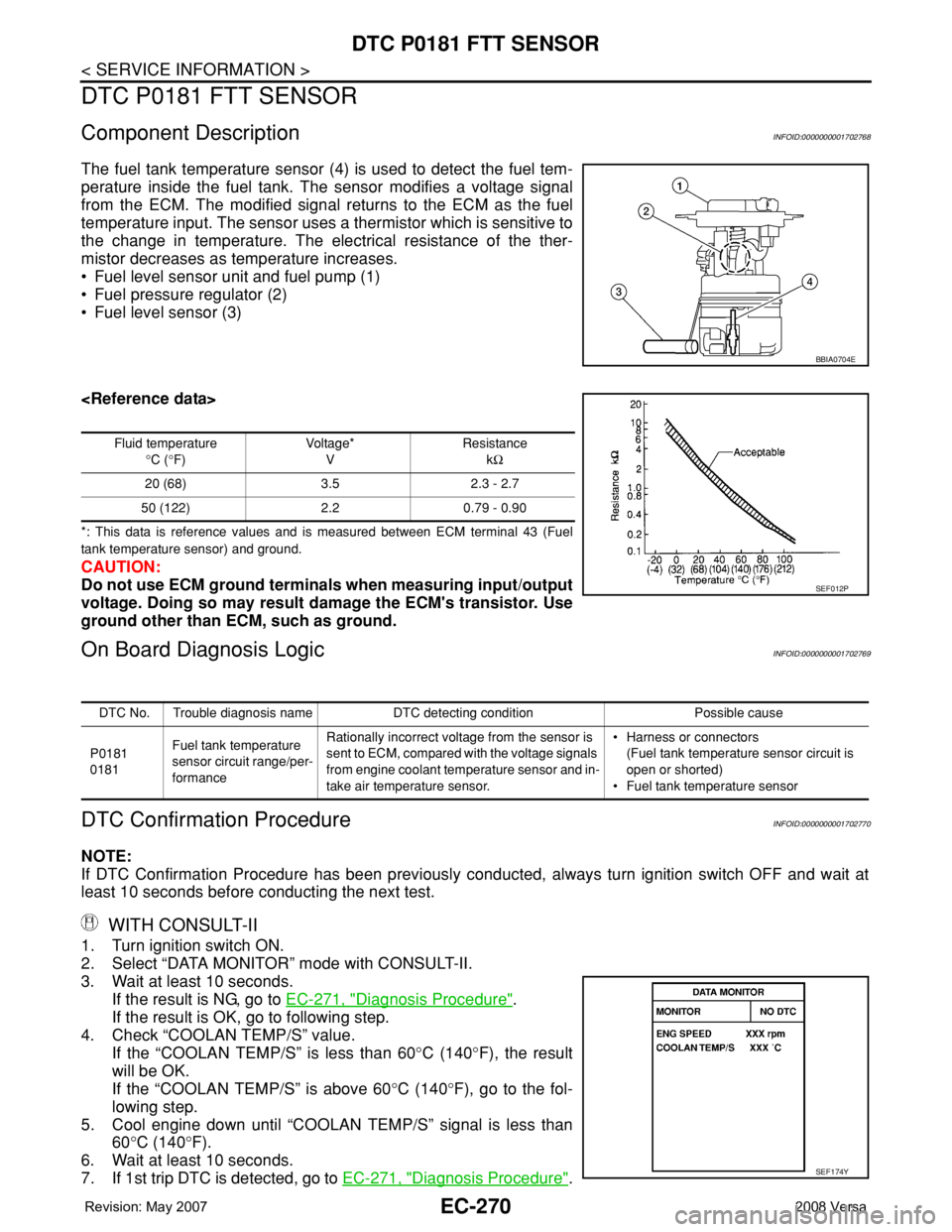
The fuel tank temperature sensor (4) is used to detect the fuel tem-
perature inside the fuel tank. The sensor modifies a voltage signal
from the ECM. The modified signal returns to the ECM as the fuel
temperature input. The sensor uses a thermistor which is sensitive to
the change in temperature. The electrical resistance of the ther-
mistor decreases as temperature increases.
• Fuel level sensor unit and fuel pump (1)
• Fuel pressure regulator (2)
• Fuel level sensor (3)
*: This data is reference values and is measured between ECM terminal 43 (Fuel
tank temperature sensor) and ground.
CAUTION:
Do not use ECM ground terminals when measuring input/output
voltage. Doing so may result damage the ECM's transistor. Use
ground other than ECM, such as ground.
On Board Diagnosis LogicINFOID:0000000001702769
DTC Confirmation ProcedureINFOID:0000000001702770
NOTE:
If DTC Confirmation Procedure has been previously conducted, always turn ignition switch OFF and wait at
least 10 seconds before conducting the next test.
WITH CONSULT-II
1. Turn ignition switch ON.
2. Select “DATA MONITOR” mode with CONSULT-II.
3. Wait at least 10 seconds.
If the result is NG, go to EC-271, "
Diagnosis Procedure".
If the result is OK, go to following step.
4. Check “COOLAN TEMP/S” value.
If the “COOLAN TEMP/S” is less than 60°C (140°F), the result
will be OK.
If the “COOLAN TEMP/S” is above 60°C (140°F), go to the fol-
lowing step.
5. Cool engine down until “COOLAN TEMP/S” signal is less than
60°C (140°F).
6. Wait at least 10 seconds.
7. If 1st trip DTC is detected, go to EC-271, "
Diagnosis Procedure".
BBIA0704E
Fluid temperature
°C (°F)Voltage*
VResistance
kΩ
20 (68) 3.5 2.3 - 2.7
50 (122) 2.2 0.79 - 0.90
SEF012P
DTC No. Trouble diagnosis name DTC detecting condition Possible cause
P0181
0181Fuel tank temperature
sensor circuit range/per-
formanceRationally incorrect voltage from the sensor is
sent to ECM, compared with the voltage signals
from engine coolant temperature sensor and in-
take air temperature sensor.• Harness or connectors
(Fuel tank temperature sensor circuit is
open or shorted)
• Fuel tank temperature sensor
SEF174Y
Page 1348 of 2771
EC-274
< SERVICE INFORMATION >
DTC P0182, P0183 FTT SENSOR
DTC P0182, P0183 FTT SENSOR
Component DescriptionINFOID:0000000001702775
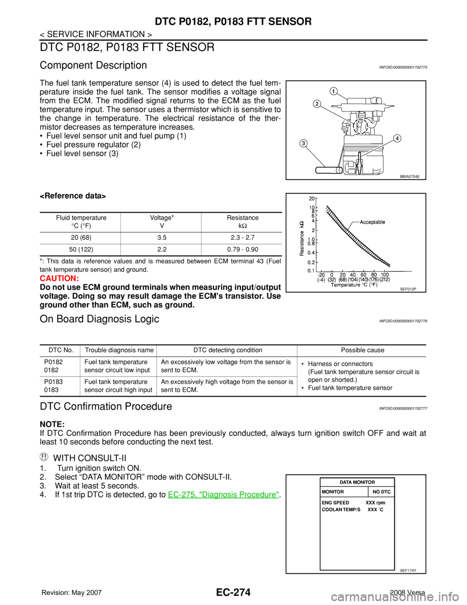
The fuel tank temperature sensor (4) is used to detect the fuel tem-
perature inside the fuel tank. The sensor modifies a voltage signal
from the ECM. The modified signal returns to the ECM as the fuel
temperature input. The sensor uses a thermistor which is sensitive to
the change in temperature. The electrical resistance of the ther-
mistor decreases as temperature increases.
• Fuel level sensor unit and fuel pump (1)
• Fuel pressure regulator (2)
• Fuel level sensor (3)
*: This data is reference values and is measured between ECM terminal 43 (Fuel
tank temperature sensor) and ground.
CAUTION:
Do not use ECM ground terminals when measuring input/output
voltage. Doing so may result damage the ECM's transistor. Use
ground other than ECM, such as ground.
On Board Diagnosis LogicINFOID:0000000001702776
DTC Confirmation ProcedureINFOID:0000000001702777
NOTE:
If DTC Confirmation Procedure has been previously conducted, always turn ignition switch OFF and wait at
least 10 seconds before conducting the next test.
WITH CONSULT-II
1. Turn ignition switch ON.
2. Select “DATA MONITOR” mode with CONSULT-II.
3. Wait at least 5 seconds.
4. If 1st trip DTC is detected, go to EC-275, "
Diagnosis Procedure".
BBIA0704E
Fluid temperature
°C (°F)Voltage*
VResistance
kΩ
20 (68) 3.5 2.3 - 2.7
50 (122) 2.2 0.79 - 0.90
SEF012P
DTC No. Trouble diagnosis name DTC detecting condition Possible cause
P0182
0182Fuel tank temperature
sensor circuit low inputAn excessively low voltage from the sensor is
sent to ECM.• Harness or connectors
(Fuel tank temperature sensor circuit is
open or shorted.)
• Fuel tank temperature sensor P0183
0183Fuel tank temperature
sensor circuit high inputAn excessively high voltage from the sensor is
sent to ECM.
SEF174Y
Page 1361 of 2771
DTC P0300 - P0304 MULTIPLE CYLINDER MISFIRE, NO. 1 - 4 CYLINDER MIS-
FIRE
EC-287
< SERVICE INFORMATION >
C
D
E
F
G
H
I
J
K
L
MA
EC
N
P O
8. Crank engine for 5 seconds or more to remove combustion gas in the cylinder.
9. Connect spark plug and harness connector to ignition coil.
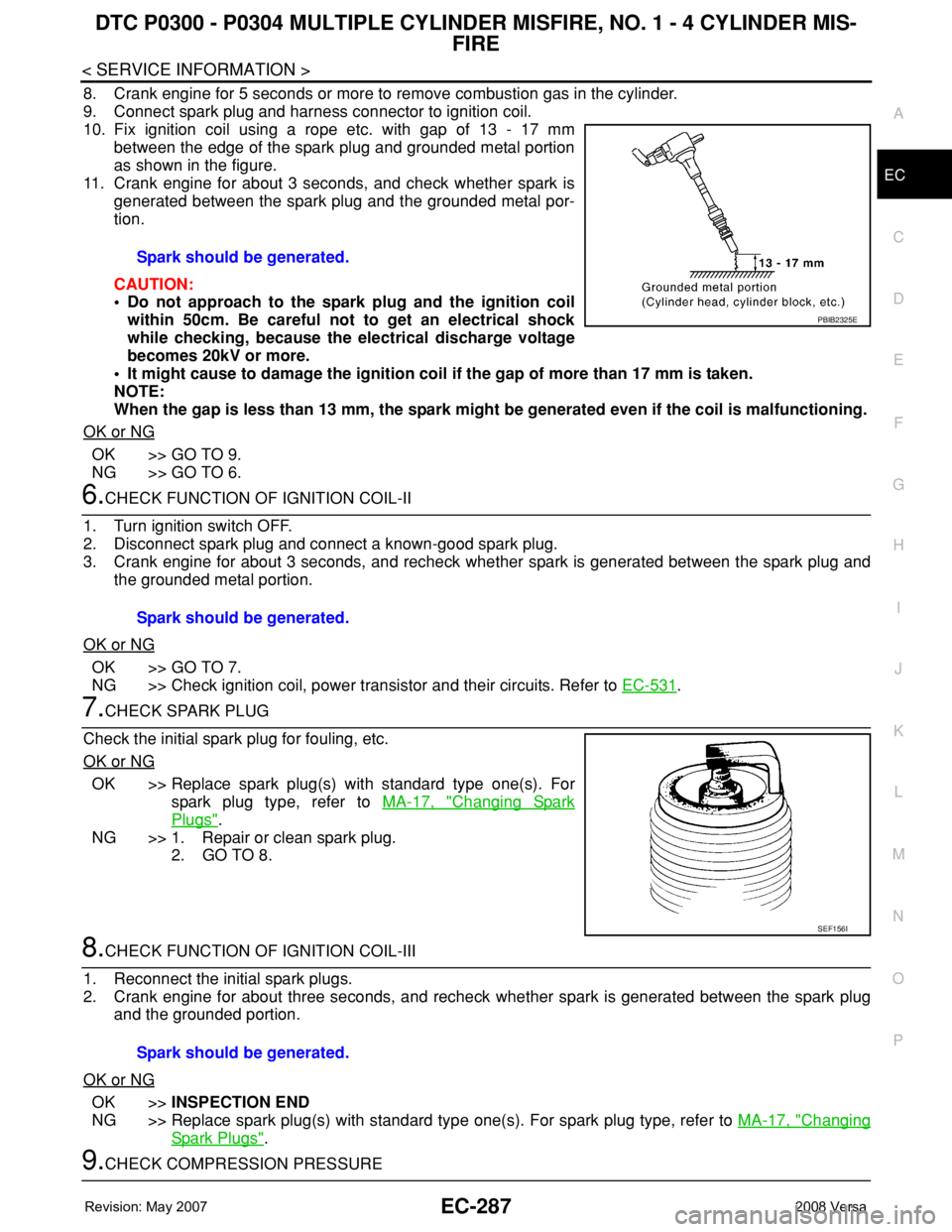
10. Fix ignition coil using a rope etc. with gap of 13 - 17 mm
between the edge of the spark plug and grounded metal portion
as shown in the figure.
11. Crank engine for about 3 seconds, and check whether spark is
generated between the spark plug and the grounded metal por-
tion.
CAUTION:
• Do not approach to the spark plug and the ignition coil
within 50cm. Be careful not to get an electrical shock
while checking, because the electrical discharge voltage
becomes 20kV or more.
• It might cause to damage the ignition coil if the gap of more than 17 mm is taken.
NOTE:
When the gap is less than 13 mm, the spark might be generated even if the coil is malfunctioning.
OK or NG
OK >> GO TO 9.
NG >> GO TO 6.
6.CHECK FUNCTION OF IGNITION COIL-II
1. Turn ignition switch OFF.
2. Disconnect spark plug and connect a known-good spark plug.
3. Crank engine for about 3 seconds, and recheck whether spark is generated between the spark plug and
the grounded metal portion.
OK or NG
OK >> GO TO 7.
NG >> Check ignition coil, power transistor and their circuits. Refer to EC-531
.
7.CHECK SPARK PLUG
Check the initial spark plug for fouling, etc.
OK or NG
OK >> Replace spark plug(s) with standard type one(s). For
spark plug type, refer to MA-17, "
Changing Spark
Plugs".
NG >> 1. Repair or clean spark plug.
2. GO TO 8.
8.CHECK FUNCTION OF IGNITION COIL-III
1. Reconnect the initial spark plugs.
2. Crank engine for about three seconds, and recheck whether spark is generated between the spark plug
and the grounded portion.
OK or NG
OK >>INSPECTION END
NG >> Replace spark plug(s) with standard type one(s). For spark plug type, refer to MA-17, "
Changing
Spark Plugs".
9.CHECK COMPRESSION PRESSURESpark should be generated.
PBIB2325E
Spark should be generated.
SEF156I
Spark should be generated.
Page 1385 of 2771
DTC P0420 THREE WAY CATALYST FUNCTION
EC-311
< SERVICE INFORMATION >
C
D
E
F
G
H
I
J
K
L
MA
EC
N
P O
OK >> GO TO 6.
NG >> Perform EC-523, "
Diagnosis Procedure".
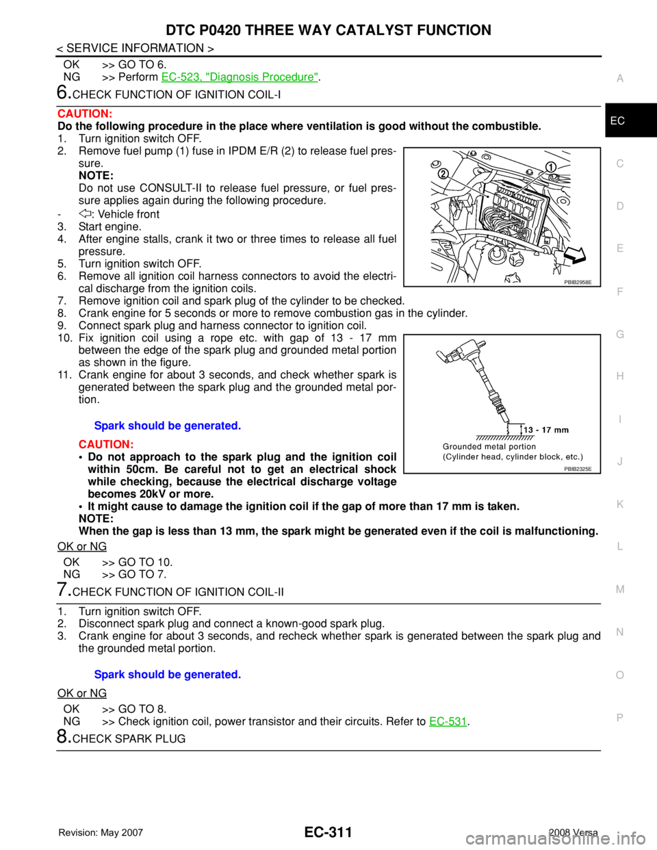
6.CHECK FUNCTION OF IGNITION COIL-I
CAUTION:
Do the following procedure in the place where ventilation is good without the combustible.
1. Turn ignition switch OFF.
2. Remove fuel pump (1) fuse in IPDM E/R (2) to release fuel pres-
sure.
NOTE:
Do not use CONSULT-II to release fuel pressure, or fuel pres-
sure applies again during the following procedure.
- : Vehicle front
3. Start engine.
4. After engine stalls, crank it two or three times to release all fuel
pressure.
5. Turn ignition switch OFF.
6. Remove all ignition coil harness connectors to avoid the electri-
cal discharge from the ignition coils.
7. Remove ignition coil and spark plug of the cylinder to be checked.
8. Crank engine for 5 seconds or more to remove combustion gas in the cylinder.
9. Connect spark plug and harness connector to ignition coil.
10. Fix ignition coil using a rope etc. with gap of 13 - 17 mm
between the edge of the spark plug and grounded metal portion
as shown in the figure.
11. Crank engine for about 3 seconds, and check whether spark is
generated between the spark plug and the grounded metal por-
tion.
CAUTION:
• Do not approach to the spark plug and the ignition coil
within 50cm. Be careful not to get an electrical shock
while checking, because the electrical discharge voltage
becomes 20kV or more.
• It might cause to damage the ignition coil if the gap of more than 17 mm is taken.
NOTE:
When the gap is less than 13 mm, the spark might be generated even if the coil is malfunctioning.
OK or NG
OK >> GO TO 10.
NG >> GO TO 7.
7.CHECK FUNCTION OF IGNITION COIL-II
1. Turn ignition switch OFF.
2. Disconnect spark plug and connect a known-good spark plug.
3. Crank engine for about 3 seconds, and recheck whether spark is generated between the spark plug and
the grounded metal portion.
OK or NG
OK >> GO TO 8.
NG >> Check ignition coil, power transistor and their circuits. Refer to EC-531
.
8.CHECK SPARK PLUGSpark should be generated.
PBIB2958E
PBIB2325E
Spark should be generated.
Page 1506 of 2771
EC-432
< SERVICE INFORMATION >
DTC P1564 ASCD STEERING SWITCH
DTC P1564 ASCD STEERING SWITCH
Component DescriptionINFOID:0000000001702951
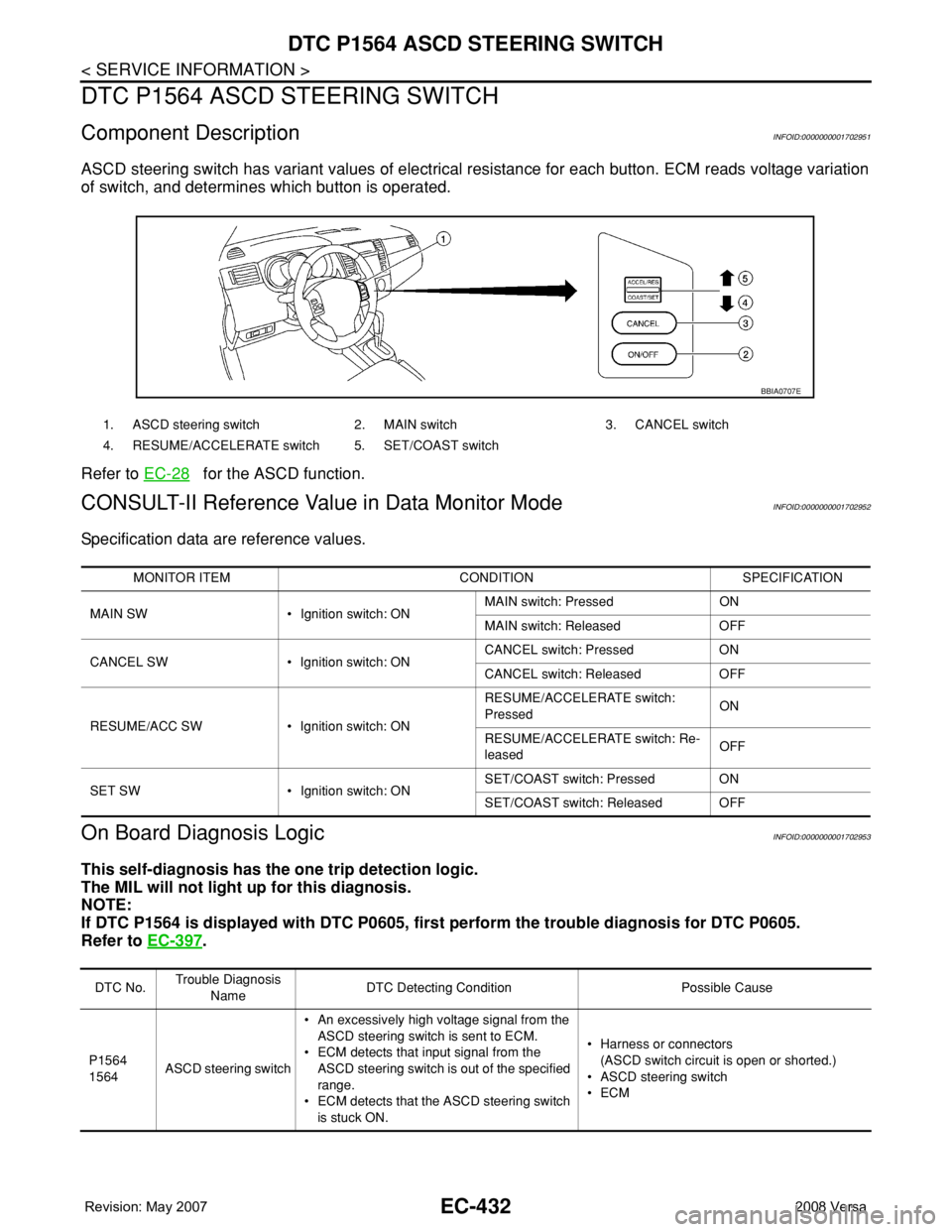
ASCD steering switch has variant values of electrical resistance for each button. ECM reads voltage variation
of switch, and determines which button is operated.
Refer to EC-28
for the ASCD function.
CONSULT-II Reference Value in Data Monitor ModeINFOID:0000000001702952
Specification data are reference values.
On Board Diagnosis LogicINFOID:0000000001702953
This self-diagnosis has the one trip detection logic.
The MIL will not light up for this diagnosis.
NOTE:
If DTC P1564 is displayed with DTC P0605, first perform the trouble diagnosis for DTC P0605.
Refer to EC-397
.
1. ASCD steering switch 2. MAIN switch 3. CANCEL switch
4. RESUME/ACCELERATE switch 5. SET/COAST switch
BBIA0707E
MONITOR ITEM CONDITION SPECIFICATION
MAIN SW • Ignition switch: ONMAIN switch: Pressed ON
MAIN switch: Released OFF
CANCEL SW • Ignition switch: ONCANCEL switch: Pressed ON
CANCEL switch: Released OFF
RESUME/ACC SW • Ignition switch: ONRESUME/ACCELERATE switch:
PressedON
RESUME/ACCELERATE switch: Re-
leasedOFF
SET SW • Ignition switch: ONSET/COAST switch: Pressed ON
SET/COAST switch: Released OFF
DTC No.Trouble Diagnosis
NameDTC Detecting Condition Possible Cause
P1564
1564ASCD steering switch• An excessively high voltage signal from the
ASCD steering switch is sent to ECM.
• ECM detects that input signal from the
ASCD steering switch is out of the specified
range.
• ECM detects that the ASCD steering switch
is stuck ON.• Harness or connectors
(ASCD switch circuit is open or shorted.)
•ASCD steering switch
•ECM
Page 1593 of 2771
ELECTRICAL LOAD SIGNAL
EC-519
< SERVICE INFORMATION >
C
D
E
F
G
H
I
J
K
L
MA
EC
N
P O
ELECTRICAL LOAD SIGNAL
CONSULT-II Reference Value in Data Monitor ModeINFOID:0000000001703057
Specification data are reference values.
Diagnosis ProcedureINFOID:0000000001703058
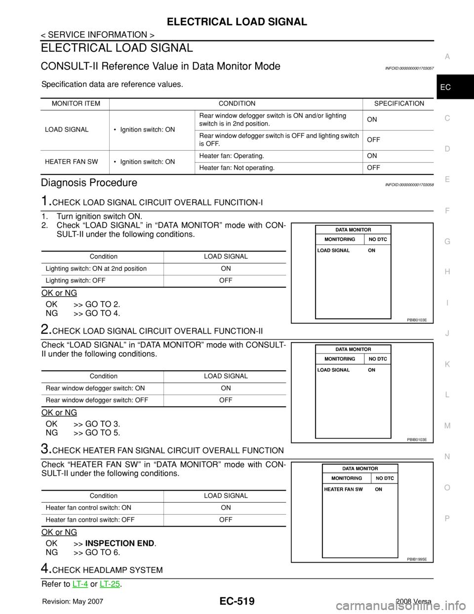
1.CHECK LOAD SIGNAL CIRCUIT OVERALL FUNCITION-I
1. Turn ignition switch ON.
2. Check “LOAD SIGNAL” in “DATA MONITOR” mode with CON-
SULT-II under the following conditions.
OK or NG
OK >> GO TO 2.
NG >> GO TO 4.
2.CHECK LOAD SIGNAL CIRCUIT OVERALL FUNCTION-II
Check “LOAD SIGNAL” in “DATA MONITOR” mode with CONSULT-
II under the following conditions.
OK or NG
OK >> GO TO 3.
NG >> GO TO 5.
3.CHECK HEATER FAN SIGNAL CIRCUIT OVERALL FUNCTION
Check “HEATER FAN SW” in “DATA MONITOR” mode with CON-
SULT-II under the following conditions.
OK or NG
OK >>INSPECTION END.
NG >> GO TO 6.
4.CHECK HEADLAMP SYSTEM
Refer to LT- 4
or LT- 2 5.
MONITOR ITEM CONDITION SPECIFICATION
LOAD SIGNAL • Ignition switch: ONRear window defogger switch is ON and/or lighting
switch is in 2nd position.ON
Rear window defogger switch is OFF and lighting switch
is OFF.OFF
HEATER FAN SW • Ignition switch: ONHeater fan: Operating. ON
Heater fan: Not operating. OFF
Condition LOAD SIGNAL
Lighting switch: ON at 2nd position ON
Lighting switch: OFF OFF
PBIB0103E
Condition LOAD SIGNAL
Rear window defogger switch: ON ON
Rear window defogger switch: OFF OFF
PBIB0103E
Condition LOAD SIGNAL
Heater fan control switch: ON ON
Heater fan control switch: OFF OFF
PBIB1995E
Page 1594 of 2771

EC-520
< SERVICE INFORMATION >
ELECTRICAL LOAD SIGNAL
>>INSPECTION END
5.CHECK REAR WINDOW DEFOGGER SYSTEM
Refer to GW-49
.
>>INSPECTION END
6.CHECK HEATER FAN CONTROL SYSTEM
Refer to MTC-22
.
>>INSPECTION END