2008 NISSAN TIIDA steering
[x] Cancel search: steeringPage 1014 of 2771

KEY INTERLOCK CABLE
CVT-175
< SERVICE INFORMATION >
D
E
F
G
H
I
J
K
L
MA
B
CVT
N
O
P
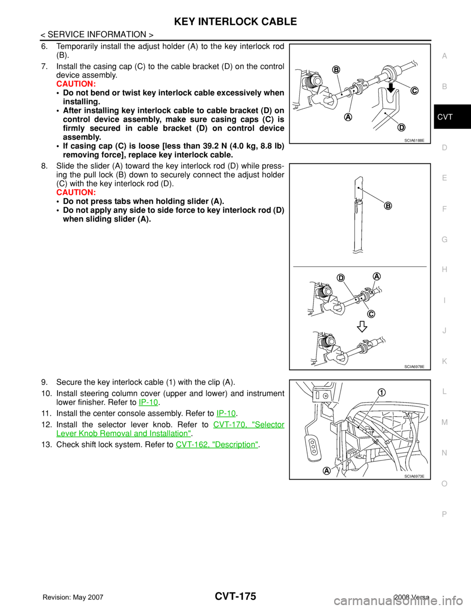
6. Temporarily install the adjust holder (A) to the key interlock rod
(B).
7. Install the casing cap (C) to the cable bracket (D) on the control
device assembly.
CAUTION:
• Do not bend or twist key interlock cable excessively when
installing.
• After installing key interlock cable to cable bracket (D) on
control device assembly, make sure casing caps (C) is
firmly secured in cable bracket (D) on control device
assembly.
• If casing cap (C) is loose [less than 39.2 N (4.0 kg, 8.8 lb)
removing force], replace key interlock cable.
8. Slide the slider (A) toward the key interlock rod (D) while press-
ing the pull lock (B) down to securely connect the adjust holder
(C) with the key interlock rod (D).
CAUTION:
• Do not press tabs when holding slider (A).
• Do not apply any side to side force to key interlock rod (D)
when sliding slider (A).
9. Secure the key interlock cable (1) with the clip (A).
10. Install steering column cover (upper and lower) and instrument
lower finisher. Refer to IP-10
.
11. Install the center console assembly. Refer to IP-10
.
12. Install the selector lever knob. Refer to CVT-170, "
Selector
Lever Knob Removal and Installation".
13. Check shift lock system. Refer to CVT-162, "
Description".
SCIA6188E
SCIA6978E
SCIA6973E
Page 1080 of 2771

EC-6
Overall Function Check .........................................406
Wiring Diagram ......................................................407
Diagnosis Procedure .............................................408
DTC P1148 CLOSED LOOP CONTROL .........411
On Board Diagnosis Logic .....................................411
DTC P1217 ENGINE OVER TEMPERATURE .412
System Description ................................................412
CONSULT-II Reference Value in Data Monitor
Mode ......................................................................
413
On Board Diagnosis Logic .....................................413
Overall Function Check .........................................413
Wiring Diagram ......................................................416
Diagnosis Procedure .............................................417
Main 13 Causes of Overheating ............................424
Component Inspection ...........................................424
DTC P1225 TP SENSOR .................................426
Component Description .........................................426
On Board Diagnosis Logic .....................................426
DTC Confirmation Procedure ................................426
Diagnosis Procedure .............................................426
Removal and Installation .......................................427
DTC P1226 TP SENSOR .................................428
Component Description .........................................428
On Board Diagnosis Logic .....................................428
DTC Confirmation Procedure ................................428
Diagnosis Procedure .............................................428
Removal and Installation .......................................429
DTC P1421 COLD START CONTROL ............430
Description .............................................................430
On Board Diagnosis Logic .....................................430
DTC Confirmation Procedure ................................430
Diagnosis Procedure .............................................430
DTC P1564 ASCD STEERING SWITCH .........432
Component Description .........................................432
CONSULT-II Reference Value in Data Monitor
Mode ......................................................................
432
On Board Diagnosis Logic .....................................432
DTC Confirmation Procedure ................................433
Wiring Diagram ......................................................434
Diagnosis Procedure .............................................435
Component Inspection ...........................................437
DTC P1572 ASCD BRAKE SWITCH ..............438
Component Description .........................................438
CONSULT-II Reference Value in Data Monitor
Mode ......................................................................
438
On Board Diagnosis Logic .....................................438
DTC Confirmation Procedure ................................439
Wiring Diagram ......................................................440
Diagnosis Procedure .............................................441
Component Inspection ...........................................445
DTC P1574 ASCD VEHICLE SPEED SEN-
SOR ..................................................................
447
Component Description .........................................447
On Board Diagnosis Logic ....................................447
DTC Confirmation Procedure ................................447
Diagnosis Procedure .............................................448
DTC P1715 INPUT SPEED SENSOR (TUR-
BINE REVOLUTION SENSOR) ........................
449
Description ............................................................449
CONSULT-II Reference Value in Data Monitor
Mode .....................................................................
449
On Board Diagnosis Logic ....................................449
Diagnosis Procedure .............................................449
DTC P1715 INPUT SPEED SENSOR (PRIMA-
RY SPEED SENSOR) .......................................
450
Description ............................................................450
CONSULT-II Reference Value in Data Monitor
Mode .....................................................................
450
On Board Diagnosis Logic ....................................450
DTC Confirmation Procedure ................................450
Diagnosis Procedure .............................................451
DTC P1805 BRAKE SWITCH ..........................452
Description ............................................................452
CONSULT-II Reference Value in Data Monitor
Mode .....................................................................
452
On Board Diagnosis Logic ....................................452
DTC Confirmation Procedure ................................452
Wiring Diagram .....................................................453
Diagnosis Procedure .............................................454
Component Inspection ..........................................455
DTC P2100, P2103 THROTTLE CONTROL
MOTOR RELAY ................................................
456
Component Description ........................................456
CONSULT-II Reference Value in Data Monitor
Mode .....................................................................
456
On Board Diagnosis Logic ....................................456
DTC Confirmation Procedure ................................456
Wiring Diagram .....................................................458
Diagnosis Procedure .............................................459
DTC P2101 ELECTRIC THROTTLE CON-
TROL FUNCTION .............................................
461
Description ............................................................461
On Board Diagnosis Logic ....................................461
DTC Confirmation Procedure ................................461
Wiring Diagram .....................................................462
Diagnosis Procedure .............................................463
Component Inspection ..........................................466
Removal and Installation .......................................466
DTC P2118 THROTTLE CONTROL MOTOR ..467
Component Description ........................................467
On Board Diagnosis Logic ....................................467
DTC Confirmation Procedure ................................467
Wiring Diagram .....................................................468
Diagnosis Procedure .............................................469
Component Inspection ..........................................470
Removal and Installation .......................................470
Page 1097 of 2771

ENGINE CONTROL SYSTEM
EC-23
< SERVICE INFORMATION >
C
D
E
F
G
H
I
J
K
L
MA
EC
N
P O
*1: This sensor is not used to control the engine system under normal conditions.
*2: This signal is sent to the ECM through CAN communication line.
*3: ECM determines the start signal status by the signals of engine speed and battery voltage.
SYSTEM DESCRIPTION
The amount of fuel injected from the fuel injector is determined by the ECM. The ECM controls the length of
time the valve remains open (injection pulse duration). The amount of fuel injected is a program value in the
ECM memory. The program value is preset by engine operating conditions. These conditions are determined
by input signals (for engine speed and intake air) from the crankshaft position sensor (POS), camshaft position
sensor (PHASE) and the mass air flow sensor.
VARIOUS FUEL INJECTION INCREASE/DECREASE COMPENSATION
In addition, the amount of fuel injected is compensated to improve engine performance under various operat-
ing conditions as listed below.
• When starting the engine
• During acceleration
• Hot-engine operation
• When selector lever is changed from N to D (A/T and CVT models)
• High-load, high-speed operation
• During deceleration
• During high engine speed operation
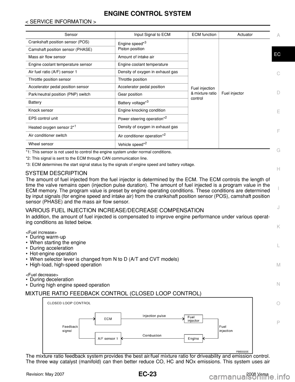
MIXTURE RATIO FEEDBACK CONTROL (CLOSED LOOP CONTROL)
The mixture ratio feedback system provides the best air/fuel mixture ratio for driveability and emission control.
The three way catalyst (manifold) can then better reduce CO, HC and NOx emissions. This system uses air
Sensor Input Signal to ECM ECM function Actuator
Crankshaft position sensor (POS)
Engine speed*
3
Piston position
Fuel injection
& mixture ratio
controlFuel injector Camshaft position sensor (PHASE)
Mass air flow sensor Amount of intake air
Engine coolant temperature sensor Engine coolant temperature
Air fuel ratio (A/F) sensor 1 Density of oxygen in exhaust gas
Throttle position sensor Throttle position
Accelerator pedal position sensor Accelerator pedal position
Park/neutral position (PNP) switch Gear position
Battery
Battery voltage*
3
Knock sensor Engine knocking condition
EPS control unit
Power steering operation*
2
Heated oxygen sensor 2*1Density of oxygen in exhaust gas
Air conditioner switch
Air conditioner operation*
2
Wheel sensor
Vehicle speed*2
PBIB3020E
Page 1101 of 2771

AIR CONDITIONING CUT CONTROL
EC-27
< SERVICE INFORMATION >
C
D
E
F
G
H
I
J
K
L
MA
EC
N
P O
AIR CONDITIONING CUT CONTROL
Input/Output Signal ChartINFOID:0000000001702558
*1: This signal is sent to the ECM through CAN communication line.
*2: ECM determines the start signal status by the signals of engine speed and battery voltage.
System DescriptionINFOID:0000000001702559
This system improves engine operation when the air conditioner is used.
Under the following conditions, the air conditioner is turned off.
• When the accelerator pedal is fully depressed.
• When cranking the engine.
• At high engine speeds.
• When the engine coolant temperature becomes excessively high.
• When operating power steering during low engine speed or low vehicle speed.
• When engine speed is excessively low.
• When refrigerant pressure is excessively low or high.
Sensor Input Signal to ECM ECM function Actuator
Air conditioner switch
Air conditioner ON signal*
1
Air conditioner
cut controlAir conditioner relay Accelerator pedal position sensor Accelerator pedal position
Crankshaft position sensor (POS)
Camshaft position sensor (PHASE)Engine speed*
2
Engine coolant temperature sensor Engine coolant temperature
Battery
Battery voltage*
2
Refrigerant pressure sensor Refrigerant pressure
EPS control unit
Power steering operation*
1
Wheel sensor
Vehicle speed*1
Page 1102 of 2771

EC-28
< SERVICE INFORMATION >
AUTOMATIC SPEED CONTROL DEVICE (ASCD)
AUTOMATIC SPEED CONTROL DEVICE (ASCD)
System DescriptionINFOID:0000000001702560
INPUT/OUTPUT SIGNAL CHART
*: This signal is sent to the ECM through CAN communication line.
BASIC ASCD SYSTEM
Refer to Owner's Manual for ASCD operating instructions.
Automatic Speed Control Device (ASCD) allows a driver to keep vehicle at predetermined constant speed
without depressing accelerator pedal. Driver can set vehicle speed in advance between approximately 40 km/
h (25 MPH) and 144 km/h (89 MPH).
ECM controls throttle angle of electric throttle control actuator to regulate engine speed.
Operation status of ASCD is indicated by CRUISE indicator and SET indicator in combination meter. If any
malfunction occurs in ASCD system, it automatically deactivates control.
NOTE:
Always drive vehicle in safe manner according to traffic conditions and obey all traffic laws.
SET OPERATION
Press MAIN switch. (The CRUISE indicator in combination meter illuminates.)
When vehicle speed reaches a desired speed between approximately 40 km/h (25 MPH) and 144 km/h (89
MPH), press SET/COAST switch. (Then SET indicator in combination meter illuminates.)
ACCELERATE OPERATION
If the RESUME/ACCELERATE switch is depressed during cruise control driving, increase the vehicle speed
until the switch is released or vehicle speed reaches maximum speed controlled by the system.
And then ASCD will keep the new set speed.
CANCEL OPERATION
When any of following conditions exist, cruise operation will be canceled.
• CANCEL switch is pressed
• More than two switches at ASCD steering switch are pressed at the same time (Set speed will be cleared)
• Brake pedal is depressed
• Clutch pedal is depressed or gear position is changed to the neutral position (M/T models)
• Selector lever is changed to N, P, R position (A/T and CVT models)
• Vehicle speed decreased to 13 km/h (8 MPH) lower than the set speed
When the ECM detects any of the following conditions, the ECM will cancel the cruise operation and inform
the driver by blinking indicator lamp.
• Engine coolant temperature is slightly higher than the normal operating temperature, CRUISE lamp may
blink slowly.
When the engine coolant temperature decreases to the normal operating temperature, CRUISE lamp will
stop blinking and the cruise operation will be able to work by pressing SET/COAST switch or RESUME/
ACCELERATE switch.
• Malfunction for some self-diagnoses regarding ASCD control: SET lamp will blink quickly.
If MAIN switch is turned to OFF during ASCD is activated, all of ASCD operations will be canceled and vehicle
speed memory will be erased.
COAST OPERATION
When the SET/COAST switch is depressed during cruise control driving, decrease vehicle set speed until the
switch is released. And then ASCD will keep the new set speed.
Sensor Input signal to ECM ECM function Actuator
ASCD brake switch Brake pedal operation
ASCD vehicle speed controlElectric throttle control
actuator Stop lamp switch Brake pedal operation
ASCD clutch switch (M/T models) Clutch pedal operation
ASCD steering switch ASCD steering switch operation
Park/neutral position (PNP) switch Gear position
Combination meter Vehicle speed*
TCM (A/T and CVT models) Powertrain revolution*
Page 1103 of 2771

AUTOMATIC SPEED CONTROL DEVICE (ASCD)
EC-29
< SERVICE INFORMATION >
C
D
E
F
G
H
I
J
K
L
MA
EC
N
P O
RESUME OPERATION
When the RESUME/ACCELERATE switch is depressed after cancel operation other than depressing MAIN
switch is performed, vehicle speed will return to last set speed. To resume vehicle set speed, vehicle condition
must meet following conditions.
• Brake pedal is released.
• Clutch pedal is released (M/T models)
• Selector lever is in other than P and N positions (A/T and CVT models)
• Vehicle speed is greater than 40 km/h (25 MPH) and less than 144 km/h (89 MPH)
Component DescriptionINFOID:0000000001702561
ASCD STEERING SWITCH
Refer to EC-432.
ASCD BRAKE SWITCH
Refer to EC-438 and EC-508.
ASCD CLUTCH SWITCH
Refer to EC-438 and EC-508.
STOP LAMP SWITCH
Refer to EC-438, EC-452and EC-508.
ELECTRIC THROTTLE CONTROL ACTUATOR
Refer to EC-456, EC-461, EC-467and EC-472.
ASCD INDICATOR
Refer to EC-516.
Page 1143 of 2771

BASIC SERVICE PROCEDURE
EC-69
< SERVICE INFORMATION >
C
D
E
F
G
H
I
J
K
L
MA
EC
N
P O
BASIC SERVICE PROCEDURE
Basic InspectionINFOID:0000000001702578
1.INSPECTION START
1. Check service records for any recent repairs that may indicate a related malfunction, or a current need for
scheduled maintenance.
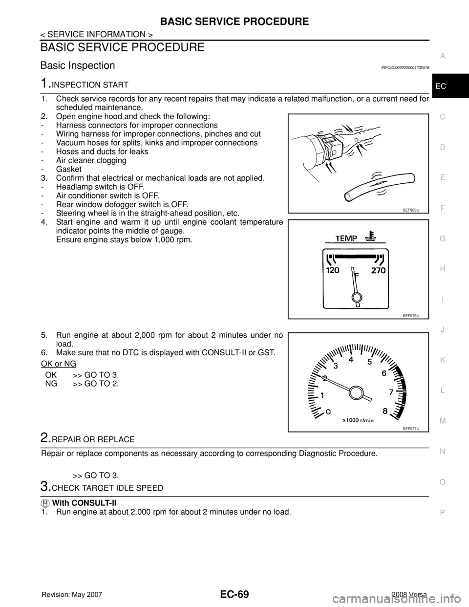
2. Open engine hood and check the following:
- Harness connectors for improper connections
- Wiring harness for improper connections, pinches and cut
- Vacuum hoses for splits, kinks and improper connections
- Hoses and ducts for leaks
- Air cleaner clogging
- Gasket
3. Confirm that electrical or mechanical loads are not applied.
- Headlamp switch is OFF.
- Air conditioner switch is OFF.
- Rear window defogger switch is OFF.
- Steering wheel is in the straight-ahead position, etc.
4. Start engine and warm it up until engine coolant temperature
indicator points the middle of gauge.
Ensure engine stays below 1,000 rpm.
5. Run engine at about 2,000 rpm for about 2 minutes under no
load.
6. Make sure that no DTC is displayed with CONSULT-II or GST.
OK or NG
OK >> GO TO 3.
NG >> GO TO 2.
2.REPAIR OR REPLACE
Repair or replace components as necessary according to corresponding Diagnostic Procedure.
>> GO TO 3.
3.CHECK TARGET IDLE SPEED
With CONSULT-II
1. Run engine at about 2,000 rpm for about 2 minutes under no load.
SEF983U
SEF976U
SEF977U
Page 1150 of 2771

EC-76
< SERVICE INFORMATION >
BASIC SERVICE PROCEDURE
Accelerator Pedal Released Position Learning
INFOID:0000000001702582
DESCRIPTION
Accelerator Pedal Released Position Learning is an operation to learn the fully released position of the accel-
erator pedal by monitoring the accelerator pedal position sensor output signal. It must be performed each time
harness connector of accelerator pedal position sensor or ECM is disconnected.
OPERATION PROCEDURE
1. Make sure that accelerator pedal is fully released.
2. Turn ignition switch ON and wait at least 2 seconds.
3. Turn ignition switch OFF and wait at least 10 seconds.
4. Turn ignition switch ON and wait at least 2 seconds.
5. Turn ignition switch OFF and wait at least 10 seconds.
Throttle Valve Closed Position LearningINFOID:0000000001702583
DESCRIPTION
Throttle Valve Closed Position Learning is an operation to learn the fully closed position of the throttle valve by
monitoring the throttle position sensor output signal. It must be performed each time harness connector of
electric throttle control actuator or ECM is disconnected.
OPERATION PROCEDURE
1. Make sure that accelerator pedal is fully released.
2. Turn ignition switch ON.
3. Turn ignition switch OFF and wait at least 10 seconds.
Make sure that throttle valve moves during above 10 seconds by confirming the operating sound.
Idle Air Volume LearningINFOID:0000000001702584
DESCRIPTION
Idle Air Volume Learning is an operation to learn the idle air volume that keeps each engine within the specific
range. It must be performed under any of the following conditions:
• Each time electric throttle control actuator or ECM is replaced.
• Idle speed or ignition timing is out of specification.
PREPARATION
Before performing Idle Air Volume Learning, make sure that all of the following conditions are satisfied.
Learning will be cancelled if any of the following conditions are missed for even a moment.
• Battery voltage: More than 12.9V (At idle)
• Engine coolant temperature: 70 - 95°C (158 - 203°F)
• Park/neutral position (PNP) switch: ON
• Electric load switch: OFF
[Air conditioner, headlamp, rear window defogger]
On vehicles equipped with daytime light systems, if the parking brake is applied before the engine is
started the headlamp will not be illuminated.
• Steering wheel: Neutral (Straight-ahead position)
• Vehicle speed: Stopped
• Transmission: Warmed-up
- Models with CONSULT-II (A/T and CVT models)
• Drive vehicle until “FLUID TEMP SE” in “DATA MONITOR” mode of “A/T” or “CVT” system indicates less
than 0.9V.
- Models without CONSULT-II (A/T and CVT models) and M/T models
• Drive vehicle for 10 minutes.
OPERATION PROCEDURE
With CONSULT-II
1. Perform EC-76, "Accelerator Pedal Released Position Learning".
2. Perform EC-76, "
Throttle Valve Closed Position Learning".