2008 NISSAN TIIDA steering
[x] Cancel search: steeringPage 407 of 2771
AV-48
< SERVICE INFORMATION >
TELEPHONE
Bluetooth Control Unit Self-Diagnosis Function
INFOID:0000000001704682
The Bluetooth control unit has two diagnostic checks. The first diagnostic check is performed automatically
every ignition cycle during control unit initialization. The second diagnostic check is performed by the techni-
cian using the steering wheel audio control switches prior to trouble diagnosis.
BLUETOOTH CONTROL UNIT INITIALIZATION CHECKS
• Internal control unit failure
• Bluetooth antenna connection open or shorted
• Steering wheel audio control switches (SEND/END) stuck closed
• Vehicle speed pulse count
• Bluetooth Microphone connection test (with playback to operator)
• Bluetooth inquiry check
SELF-DIAGNOSIS MODE
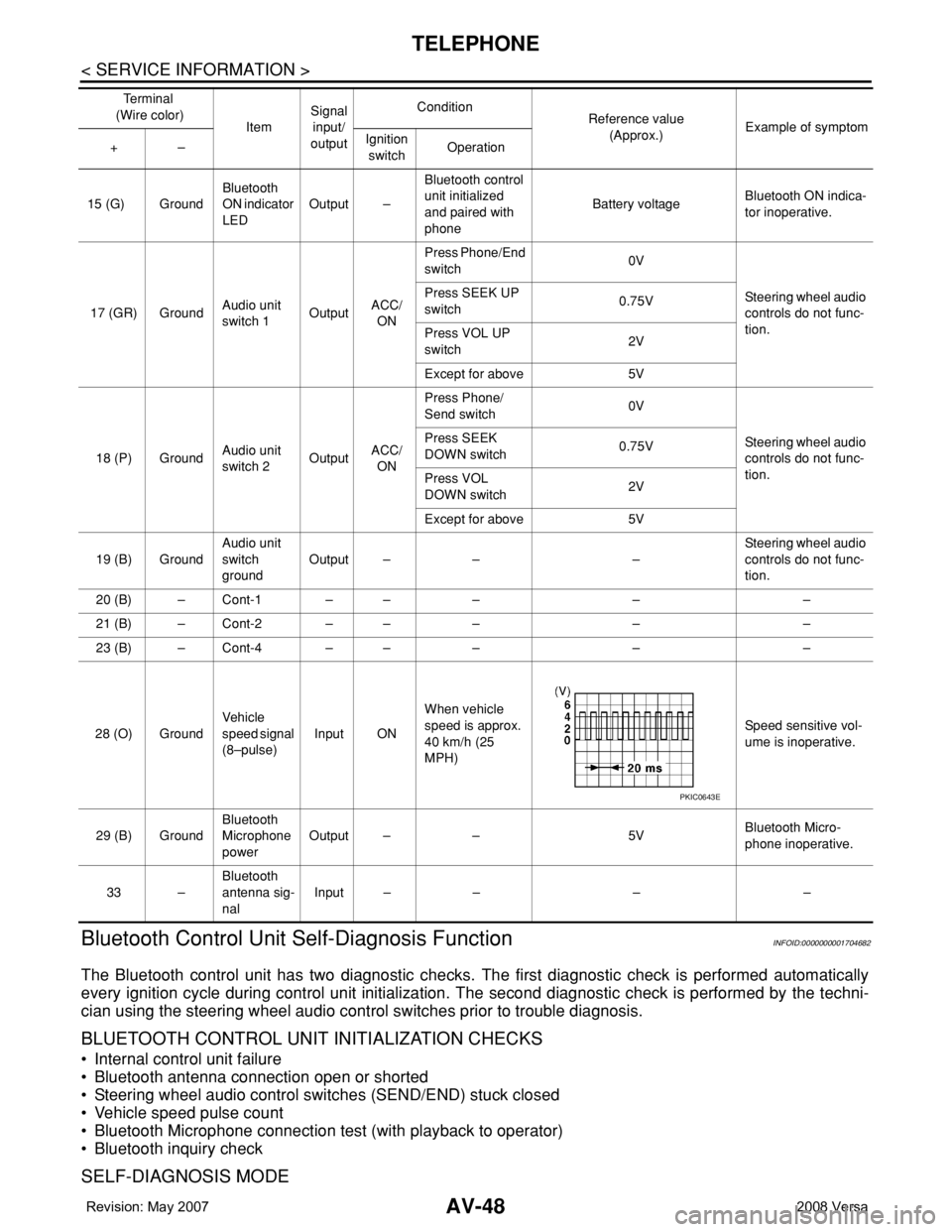
15 (G) GroundBluetooth
ON indicator
LEDOutput –Bluetooth control
unit initialized
and paired with
phoneBattery voltageBluetooth ON indica-
tor inoperative.
17 (GR) GroundAudio unit
switch 1OutputACC/
ONPress Phone/End
switch 0V
Steering wheel audio
controls do not func-
tion. Press SEEK UP
switch0.75V
Press VOL UP
switch2V
Except for above 5V
18 (P) GroundAudio unit
switch 2OutputACC/
ONPress Phone/
Send switch 0V
Steering wheel audio
controls do not func-
tion. Press SEEK
DOWN switch0.75V
Press VOL
DOWN switch2V
Except for above 5V
19 (B) GroundAudio unit
switch
groundOutput – – –Steering wheel audio
controls do not func-
tion.
20 (B) – Cont-1 – – – – –
21 (B) – Cont-2 – – – – –
23 (B) – Cont-4 – – – – –
28 (O) GroundVehicle
speed signal
(8–pulse)Input ONWhen vehicle
speed is approx.
40 km/h (25
MPH)Speed sensitive vol-
ume is inoperative.
29 (B) GroundBluetooth
Microphone
powerOutput – – 5VBluetooth Micro-
phone inoperative.
33 –Bluetooth
antenna sig-
nalInput – – – – Te r m i n a l
(Wire color)
ItemSignal
input/
outputCondition
Reference value
(Approx.)Example of symptom
+–Ignition
switchOperation
PKIC0643E
Page 408 of 2771
TELEPHONE
AV-49
< SERVICE INFORMATION >
C
D
E
F
G
H
I
J
L
MA
B
AV
N
O
P
1. Turn ignition switch to ACC or ON.
2. Wait for the Bluetooth system to complete initialization and the Bluetooth ON indicator to stop flashing.
This may take up to 10 seconds.
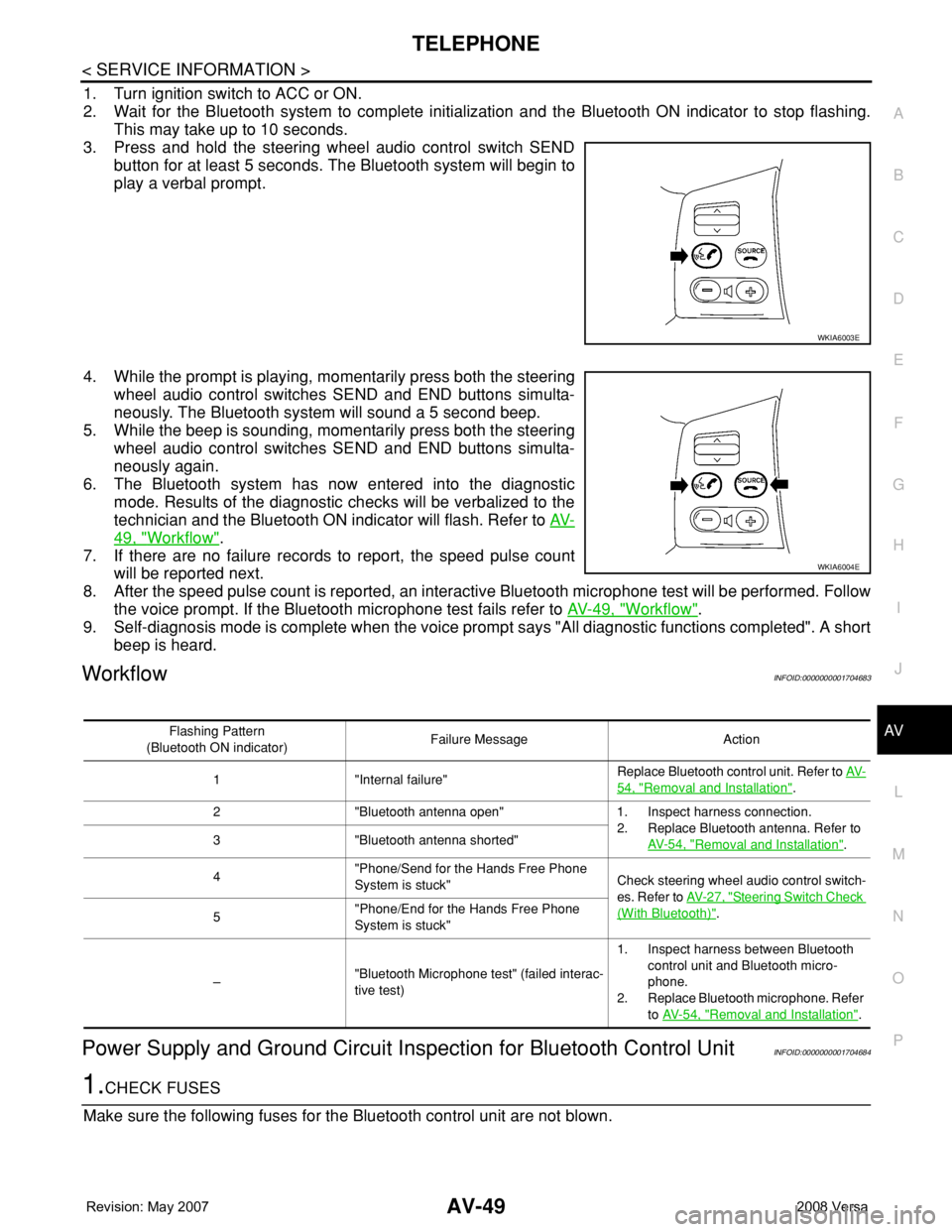
3. Press and hold the steering wheel audio control switch SEND
button for at least 5 seconds. The Bluetooth system will begin to
play a verbal prompt.
4. While the prompt is playing, momentarily press both the steering
wheel audio control switches SEND and END buttons simulta-
neously. The Bluetooth system will sound a 5 second beep.
5. While the beep is sounding, momentarily press both the steering
wheel audio control switches SEND and END buttons simulta-
neously again.
6. The Bluetooth system has now entered into the diagnostic
mode. Results of the diagnostic checks will be verbalized to the
technician and the Bluetooth ON indicator will flash. Refer to AV-
49, "Workflow".
7. If there are no failure records to report, the speed pulse count
will be reported next.
8. After the speed pulse count is reported, an interactive Bluetooth microphone test will be performed. Follow
the voice prompt. If the Bluetooth microphone test fails refer to AV-49, "
Workflow".
9. Self-diagnosis mode is complete when the voice prompt says "All diagnostic functions completed". A short
beep is heard.
WorkflowINFOID:0000000001704683
Power Supply and Ground Circuit Inspection for Bluetooth Control UnitINFOID:0000000001704684
1.CHECK FUSES
Make sure the following fuses for the Bluetooth control unit are not blown.
WKIA6003E
WKIA6004E
Flashing Pattern
(Bluetooth ON indicator)Failure Message Action
1 "Internal failure"Replace Bluetooth control unit. Refer to AV-
54, "Removal and Installation".
2 "Bluetooth antenna open" 1. Inspect harness connection.
2. Replace Bluetooth antenna. Refer to
AV- 5 4 , "
Removal and Installation". 3 "Bluetooth antenna shorted"
4"Phone/Send for the Hands Free Phone
System is stuck"Check steering wheel audio control switch-
es. Refer to AV- 2 7 , "
Steering Switch Check
(With Bluetooth)".
5"Phone/End for the Hands Free Phone
System is stuck"
–"Bluetooth Microphone test" (failed interac-
tive test)1. Inspect harness between Bluetooth
control unit and Bluetooth micro-
phone.
2. Replace Bluetooth microphone. Refer
to AV- 5 4 , "
Removal and Installation".
Page 409 of 2771
AV-50
< SERVICE INFORMATION >
TELEPHONE
OK or NG
OK >> GO TO 2.
NG >> If fuse is blown, be sure to eliminate cause of malfunction before installing new fuse. Refer to PG-
3.
2.CHECK POWER SUPPLY CIRCUIT
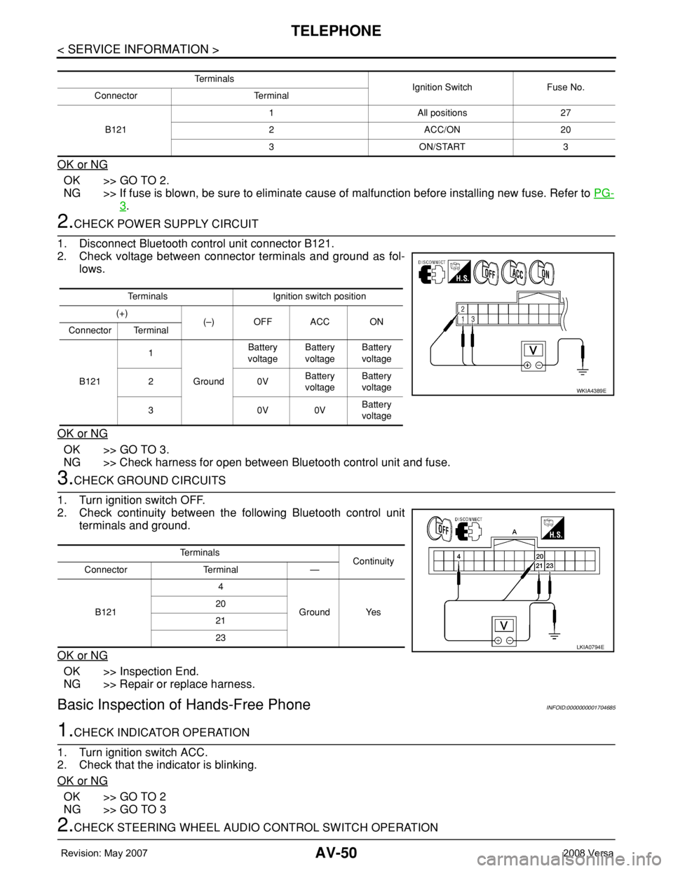
1. Disconnect Bluetooth control unit connector B121.
2. Check voltage between connector terminals and ground as fol-
lows.
OK or NG
OK >> GO TO 3.
NG >> Check harness for open between Bluetooth control unit and fuse.
3.CHECK GROUND CIRCUITS
1. Turn ignition switch OFF.
2. Check continuity between the following Bluetooth control unit
terminals and ground.
OK or NG
OK >> Inspection End.
NG >> Repair or replace harness.
Basic Inspection of Hands-Free PhoneINFOID:0000000001704685
1.CHECK INDICATOR OPERATION
1. Turn ignition switch ACC.
2. Check that the indicator is blinking.
OK or NG
OK >> GO TO 2
NG >> GO TO 3
2.CHECK STEERING WHEEL AUDIO CONTROL SWITCH OPERATION
Te r m i n a l s
Ignition Switch Fuse No.
Connector Terminal
B1211 All positions 27
2 ACC/ON 20
3 ON/START 3
Terminals Ignition switch position
(+)
(–) OFF ACC ON
Connector Terminal
B1211
GroundBattery
voltageBattery
voltageBattery
voltage
20VBattery
voltageBattery
voltage
30V0VBattery
voltage
WKIA4389E
Te r m i n a l s
Continuity
Connector Terminal —
B1214
Ground Yes 20
21
23
LKIA0794E
Page 410 of 2771
TELEPHONE
AV-51
< SERVICE INFORMATION >
C
D
E
F
G
H
I
J
L
MA
B
AV
N
O
P
1. Press the SEND switch.
2. Check the indicator is blinking.
OK or NG
OK >> INSPECTION END
NG >> Check steering wheel audio control switch circuit.
3.CHECK BLUETOOTH INDICATOR OUTPUT VOLTAGE
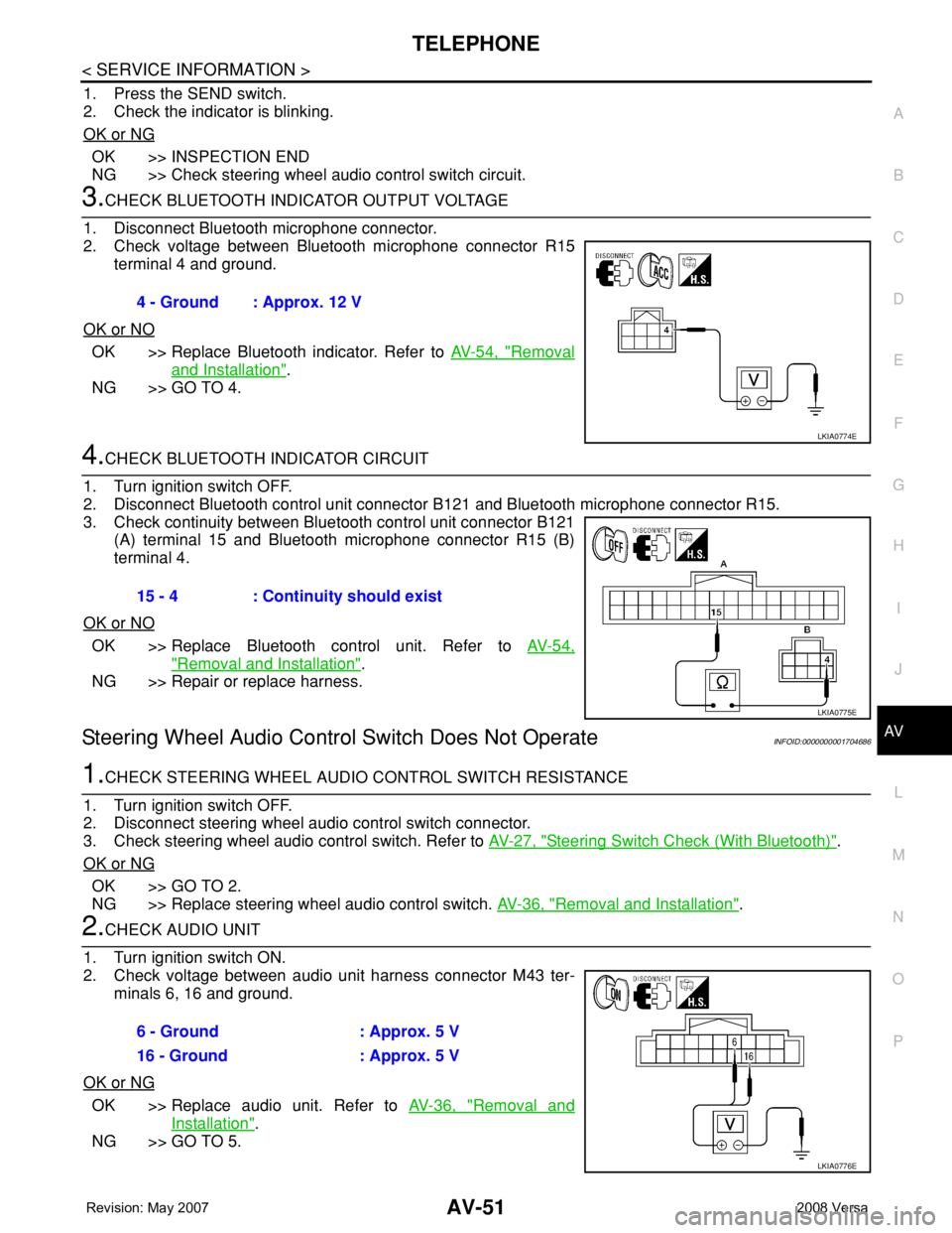
1. Disconnect Bluetooth microphone connector.
2. Check voltage between Bluetooth microphone connector R15
terminal 4 and ground.
OK or NO
OK >> Replace Bluetooth indicator. Refer to AV-54, "Removal
and Installation".
NG >> GO TO 4.
4.CHECK BLUETOOTH INDICATOR CIRCUIT
1. Turn ignition switch OFF.
2. Disconnect Bluetooth control unit connector B121 and Bluetooth microphone connector R15.
3. Check continuity between Bluetooth control unit connector B121
(A) terminal 15 and Bluetooth microphone connector R15 (B)
terminal 4.
OK or NO
OK >> Replace Bluetooth control unit. Refer to AV-54,
"Removal and Installation".
NG >> Repair or replace harness.
Steering Wheel Audio Control Switch Does Not OperateINFOID:0000000001704686
1.CHECK STEERING WHEEL AUDIO CONTROL SWITCH RESISTANCE
1. Turn ignition switch OFF.
2. Disconnect steering wheel audio control switch connector.
3. Check steering wheel audio control switch. Refer to AV-27, "
Steering Switch Check (With Bluetooth)".
OK or NG
OK >> GO TO 2.
NG >> Replace steering wheel audio control switch. AV-36, "
Removal and Installation".
2.CHECK AUDIO UNIT
1. Turn ignition switch ON.
2. Check voltage between audio unit harness connector M43 ter-
minals 6, 16 and ground.
OK or NG
OK >> Replace audio unit. Refer to AV-36, "Removal and
Installation".
NG >> GO TO 5.4 - Ground : Approx. 12 V
LKIA0774E
15 - 4 : Continuity should exist
LKIA0775E
6 - Ground : Approx. 5 V
16 - Ground : Approx. 5 V
LKIA0776E
Page 411 of 2771
AV-52
< SERVICE INFORMATION >
TELEPHONE
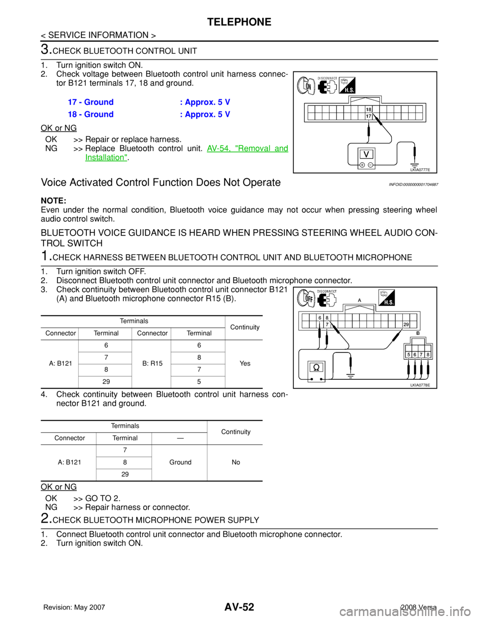
3.CHECK BLUETOOTH CONTROL UNIT
1. Turn ignition switch ON.
2. Check voltage between Bluetooth control unit harness connec-
tor B121 terminals 17, 18 and ground.
OK or NG
OK >> Repair or replace harness.
NG >> Replace Bluetooth control unit. AV-54, "
Removal and
Installation".
Voice Activated Control Function Does Not OperateINFOID:0000000001704687
NOTE:
Even under the normal condition, Bluetooth voice guidance may not occur when pressing steering wheel
audio control switch.
BLUETOOTH VOICE GUIDANCE IS HEARD WHEN PRESSING STEERING WHEEL AUDIO CON-
TROL SWITCH
1.CHECK HARNESS BETWEEN BLUETOOTH CONTROL UNIT AND BLUETOOTH MICROPHONE
1. Turn ignition switch OFF.
2. Disconnect Bluetooth control unit connector and Bluetooth microphone connector.
3. Check continuity between Bluetooth control unit connector B121
(A) and Bluetooth microphone connector R15 (B).
4. Check continuity between Bluetooth control unit harness con-
nector B121 and ground.
OK or NG
OK >> GO TO 2.
NG >> Repair harness or connector.
2.CHECK BLUETOOTH MICROPHONE POWER SUPPLY
1. Connect Bluetooth control unit connector and Bluetooth microphone connector.
2. Turn ignition switch ON.17 - Ground : Approx. 5 V
18 - Ground : Approx. 5 V
LKIA0777E
Te r m i n a l s
Continuity
Connector Terminal Connector Terminal
A: B1216
B: R156
Ye s 78
87
29 5
Te r m i n a l s
Continuity
Connector Terminal —
A: B1217
Ground No 8
29
LKIA0778E
Page 412 of 2771
TELEPHONE
AV-53
< SERVICE INFORMATION >
C
D
E
F
G
H
I
J
L
MA
B
AV
N
O
P
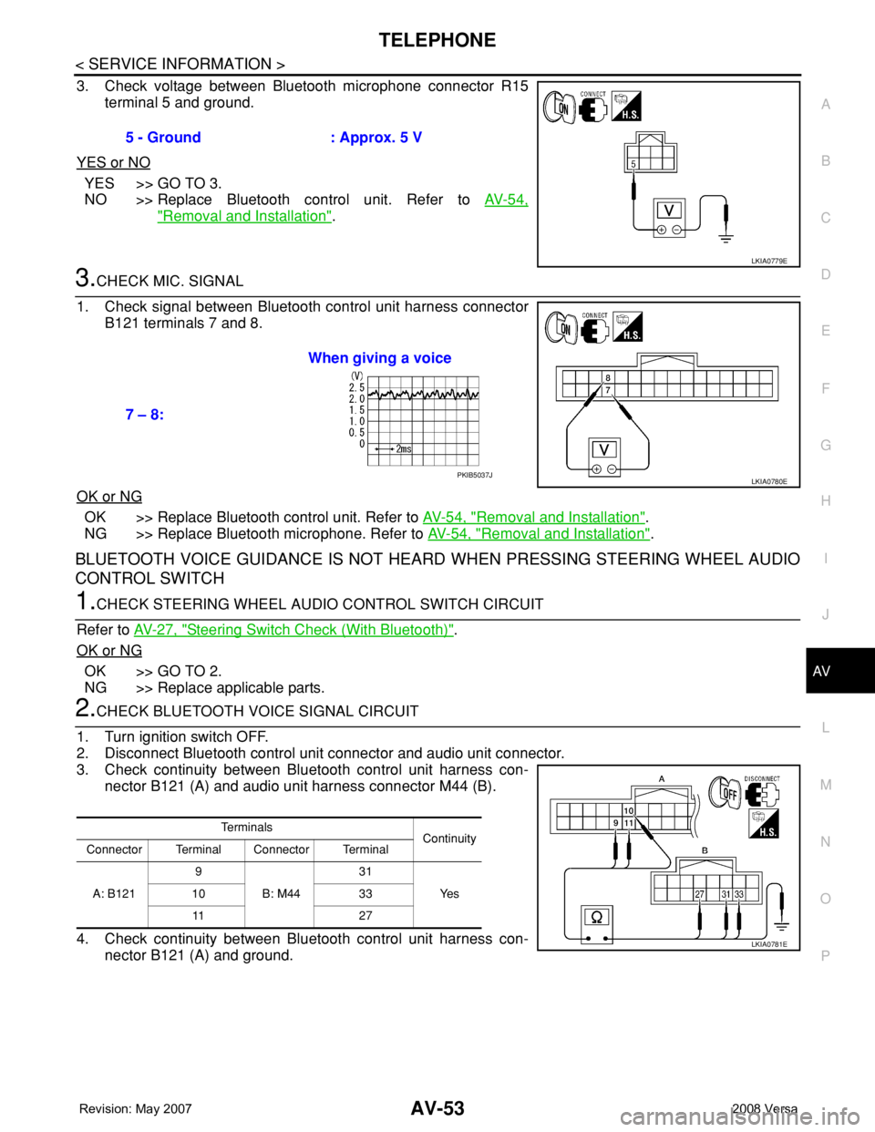
3. Check voltage between Bluetooth microphone connector R15
terminal 5 and ground.
YES or NO
YES >> GO TO 3.
NO >> Replace Bluetooth control unit. Refer to AV-54,
"Removal and Installation".
3.CHECK MIC. SIGNAL
1. Check signal between Bluetooth control unit harness connector
B121 terminals 7 and 8.
OK or NG
OK >> Replace Bluetooth control unit. Refer to AV-54, "Removal and Installation".
NG >> Replace Bluetooth microphone. Refer to AV-54, "
Removal and Installation".
BLUETOOTH VOICE GUIDANCE IS NOT HEARD WHEN PRESSING STEERING WHEEL AUDIO
CONTROL SWITCH
1.CHECK STEERING WHEEL AUDIO CONTROL SWITCH CIRCUIT
Refer to AV-27, "
Steering Switch Check (With Bluetooth)".
OK or NG
OK >> GO TO 2.
NG >> Replace applicable parts.
2.CHECK BLUETOOTH VOICE SIGNAL CIRCUIT
1. Turn ignition switch OFF.
2. Disconnect Bluetooth control unit connector and audio unit connector.
3. Check continuity between Bluetooth control unit harness con-
nector B121 (A) and audio unit harness connector M44 (B).
4. Check continuity between Bluetooth control unit harness con-
nector B121 (A) and ground.5 - Ground : Approx. 5 V
LKIA0779E
7 – 8:When giving a voice
LKIA0780EPKIB5037J
Te r m i n a l s
Continuity
Connector Terminal Connector Terminal
A: B1219
B: M4431
Ye s 10 33
11 2 7
LKIA0781E
Page 435 of 2771

BL-1
BODY
C
D
E
F
G
H
J
K
L
M
SECTION BL
A
B
BL
N
O
P
CONTENTS
BODY, LOCK & SECURITY SYSTEM
SERVICE INFORMATION ............................4
PRECAUTIONS ...................................................4
Precaution for Supplemental Restraint System
(SRS) "AIR BAG" and "SEAT BELT PRE-TEN-
SIONER" ...................................................................
4
Precaution Necessary for Steering Wheel Rota-
tion After Battery Disconnect .....................................
4
Precaution for Procedure without Cowl Top Cover ......5
Precaution for Work ..................................................5
PREPARATION ...................................................6
Special Service Tool .................................................6
Commercial Service Tool ..........................................6
SQUEAK AND RATTLE TROUBLE DIAG-
NOSES ................................................................
7
Work Flow .................................................................7
Generic Squeak and Rattle Troubleshooting ............9
Diagnostic Worksheet .............................................11
HOOD .................................................................13
Fitting Adjustment ...................................................13
Removal and Installation .........................................14
Removal and Installation of Hood Lock Control ......15
Hood Lock Control Inspection .................................17
RADIATOR CORE SUPPORT ...........................19
Removal and Installation .........................................19
FRONT FENDER ................................................21
Removal and Installation .........................................21
POWER DOOR LOCK SYSTEM ........................22
Component Parts and Harness Connector Loca-
tion ..........................................................................
22
System Description .................................................22
CAN Communication System Description ...............24
Schematic ...............................................................25
Wiring Diagram - D/LOCK - .....................................26
Schematic ...............................................................30
Wiring Diagram - D/LOCK - .....................................31
Terminal and Reference Value for BCM ..................35
Work Flow ................................................................35
CONSULT-III Function (BCM) .................................36
Trouble Diagnosis Symptom Chart ..........................37
BCM Power Supply and Ground Circuit ..................37
Door Switch Check (Hatchback) ..............................37
Door Switch Check (Sedan) ....................................40
Key Switch (Insert) Check .......................................41
Door Lock and Unlock Switch Check ......................42
Front Door Lock Assembly LH (Actuator) Check .....45
Door Lock Actuator Check (Front RH and Rear
LH/RH) .....................................................................
46
Front Door Key Cylinder Switch LH Check ..............47
Passenger Select Unlock Relay Circuit Inspection
(With Intelligent Key) ...............................................
48
REMOTE KEYLESS ENTRY SYSTEM .............51
Component Parts and Harness Connector Loca-
tion ...........................................................................
51
System Description ..................................................51
CAN Communication System Description ...............53
Schematic ................................................................54
Wiring Diagram - KEYLES - ....................................55
Terminal and Reference Value for BCM ..................57
How to Perform Trouble Diagnosis ..........................57
Preliminary Check ...................................................58
CONSULT-III Function (BCM) .................................58
Work Flow ................................................................59
Trouble Diagnosis Symptom Chart ..........................60
Keyfob Battery and Function Check ........................61
ACC Switch Check ..................................................62
Door Switch Check (Hatchback) ..............................62
Door Switch Check (Sedan) ....................................65
Key Switch (Insert) Check .......................................66
Hazard Function Check ...........................................67
Horn Function Check ...............................................67
Interior Lamp and Ignition Keyhole Illumination
Function Check ........................................................
68
Remote Keyless Entry Receiver Check ...................68
Keyfob Function (Lock) Check ................................71
Keyfob Function (Unlock) Check .............................71
Page 436 of 2771

BL-2
ID Code Entry Procedure .......................................71
Keyfob Battery Replacement ..................................73
Removal and Installation of Remote Keyless Entry
Receiver .................................................................
73
INTELLIGENT KEY SYSTEM ............................74
Component Parts and Harness Connector Loca-
tion ..........................................................................
74
System Description .................................................76
CAN Communication System Description ..............83
Schematic ...............................................................84
Wiring Diagram - I/KEY - ........................................86
Intelligent Key Unit Harness Connector Terminal
Layout .....................................................................
96
Terminal and Reference Value for Intelligent Key
Unit .........................................................................
96
Steering Lock Solenoid Harness Connector Ter-
minal Layout ...........................................................
98
Terminal and Reference Value for Steering Lock
Solenoid ..................................................................
98
Terminal and Reference Value for BCM .................99
Trouble Diagnosis Procedure .................................99
CONSULT-III Functions (INTELLIGENT KEY) ......100
CONSULT-III Application Item ...............................101
Trouble Diagnosis Symptom Chart ........................103
CAN Communication System Inspection ...............109
Power Supply and Ground Circuit Inspection ........110
Key Switch (Intelligent Key Unit Input) Check .......110
Key Switch (BCM Input) Check .............................112
Ignition Knob Switch Check ...................................113
Door Switch Check (Hatchback) ............................114
Door Switch Check (Sedan) ..................................117
Door Request Switch Check ..................................118
Back Door Request Switch Check (Hatchback) ....120
Trunk Opener Request Switch Check (Sedan) .....122
Unlock Sensor Check ............................................124
Intelligent Key Warning Buzzer(s) Check ..............125
Outside Key Antenna (Driver Side and Passenger
Side) Check ...........................................................
126
Outside Key Antenna (Rear Bumper) Check .........128
Inside Key Antenna Check ....................................129
Steering Lock Solenoid Check ..............................131
Key Interlock Solenoid (With M/T) Check ..............133
Ignition Switch Position Check ..............................134
Stop Lamp Switch Check (With CVT) ....................134
Stop Lamp Switch Check (With M/T) .....................135
Check CVT Device (Park Position Switch) Check ..136
"P-SHIFT" Warning Lamp (With CVT) Check ........138
"LOCK" Warning Lamp (With M/T) Check .............138
"KEY" Warning Lamp (RED) Check ......................139
"KEY" Warning Lamp (GREEN) Check .................139
Check Warning Chime in Combination Meter ........140
Hazard Function Check .........................................140
Horn Function Check .............................................140
Headlamp Function Check ....................................141
Intelligent Key Battery Replacement .....................142
Remote Keyless Entry Function ............................142
Removal and Installation of Intelligent Key Unit ....142
DOOR ...............................................................144
Fitting Adjustment .................................................144
Removal and Installation .......................................147
FRONT DOOR LOCK .......................................150
Component Parts Location ...................................150
Removal and Installation .......................................150
REAR DOOR LOCK .........................................153
Component Parts Location ...................................153
Removal and Installation .......................................153
BACK DOOR LOCK .........................................156
Component Parts and Harness Connector Loca-
tion ........................................................................
156
System Description ...............................................156
Wiring Diagram - B/DOOR - ..................................157
Terminal and Reference Value for BCM ...............158
Terminal and Reference Value for Intelligent Key
Unit ........................................................................
158
CONSULT-III Function (BCM) ..............................159
Work Flow .............................................................159
Trouble Diagnosis Chart by Symptom ..................159
BCM Power Supply and Ground Circuit ................160
Check Back Door Opener Switch Circuit (Without
Intelligent Key or Power Windows) .......................
160
Check Back Door Opener Switch Circuit (Without
Intelligent Key, with Power Windows) ...................
162
Check Back Door Opener Switch Circuit (With In-
telligent Key) .........................................................
165
Check Back Door Lock Assembly (Actuator) Cir-
cuit ........................................................................
166
Removal and Installation .......................................168
TRUNK LID .......................................................170
Fitting Adjustment .................................................170
Trunk Lid Assembly ..............................................170
Trunk Lid Lock ......................................................171
Trunk Lid Striker ....................................................171
TRUNK LID OPENER .......................................173
Component Parts and Harness Connector Loca-
tion ........................................................................
173
System Description ...............................................173
Wiring Diagram - TLID - ........................................174
Terminal and Reference Value for BCM ...............175
Terminal and Reference Value for Intelligent Key
Unit ........................................................................
175
CONSULT-III Function (BCM) ..............................176
Work Flow .............................................................176
Trouble Diagnosis Chart by Symptom ..................176
BCM Power Supply and Ground Circuit ................177
Check Trunk Lid Opener Switch Circuit (Without
Intelligent Key or Power Windows) .......................
177
Check Trunk Lid Opener Switch Circuit (Without
Intelligent Key, with Power Windows) ...................
179
Check Trunk Lid Opener Switch Circuit (With Intel-
ligent Key) .............................................................
182
Check Trunk Release Solenoid Circuit .................183