Page 2707 of 2771
![NISSAN TIIDA 2008 Service Repair Manual STC-24
< SERVICE INFORMATION >[EPS]
TROUBLE DIAGNOSIS FOR SYMPTOMS
DIAGNOSTIC PROCEDURE
1.CHECK EPS WARNING LAMP
Confirm EPS warning lamp during engine running.
Does EPS warning lamp turn OFF?
YES >> NISSAN TIIDA 2008 Service Repair Manual STC-24
< SERVICE INFORMATION >[EPS]
TROUBLE DIAGNOSIS FOR SYMPTOMS
DIAGNOSTIC PROCEDURE
1.CHECK EPS WARNING LAMP
Confirm EPS warning lamp during engine running.
Does EPS warning lamp turn OFF?
YES >>](/manual-img/5/57399/w960_57399-2706.png)
STC-24
< SERVICE INFORMATION >[EPS]
TROUBLE DIAGNOSIS FOR SYMPTOMS
DIAGNOSTIC PROCEDURE
1.CHECK EPS WARNING LAMP
Confirm EPS warning lamp during engine running.
Does EPS warning lamp turn OFF?
YES >> GO TO 2.
NO >> Go to STC-21, "
EPS Warning Lamp Does Not Turn OFF" .
2.CHECK WHEEL ALIGNMENT
Check wheel alignment. Refer to FSU-6, "
Wheel Alignment Inspection" .
OK or NG
OK >> GO TO 3.
NG >> Adjust wheel alignment. Refer to FSU-6, "
Wheel Alignment Inspection" .
3.CHECK EPS CONTROL UNIT
Check EPS control unit input/output signal. Refer to STC-9, "
EPS Control Unit Input/Output Signal Reference
Va l u e" .
OK or NG
OK >> GO TO 4.
NG >> Check EPS control unit pin terminals for damage or loose connection with harness connector. If
any items are damaged, repair or replace damaged parts.
4.SYMPTOM CHECK
Check again.
OK or NG
OK >>INSPECTION END
NG >> Check the steering wheel turning force because there may be mechanical malfunction. Refer to
PS-6, "
On-Vehicle Inspection and Service" .
Unbalance Steering Wheel Turning Force (Torque Variation)INFOID:0000000001703896
SYMPTOM:
Unbalance steering wheel turning force, while driving (Torque variation).
DIAGNOSTIC PROCEDURE
1.CHECK EPS WARNING LAMP
Confirm EPS warning lamp during engine running.
Does EPS warning lamp turn OFF?
YES >> GO TO 2.
NO >> Go to STC-21, "
EPS Warning Lamp Does Not Turn OFF" .
2.CHECK STEERING COLUMN INTERMEDIATE SHAFT
Check the connection between intermediate shaft and the mounting part of steering column assembly and
steering gear assembly. Refer to PS-9, "
Removal and Installation" .
OK or NG
OK >> GO TO 3.
NG >> Repair or replace damaged parts.
3.CHECK EPS CONTROL UNIT
Check EPS control unit input/output signal. Refer to STC-9, "
EPS Control Unit Input/Output Signal Reference
Va l u e" .
OK or NG
OK >> GO TO 4.
NG >> Check EPS control unit pin terminals for damage or loose connection with harness connector. If
any items are damaged, repair or replace damaged parts.
4.SYMPTOM CHECK
Page 2708 of 2771
TROUBLE DIAGNOSIS FOR SYMPTOMS
STC-25
< SERVICE INFORMATION >[EPS]
C
D
E
F
H
I
J
K
L
MA
B
STC
N
O
P
Check again.
OK or NG
OK >>INSPECTION END
NG >> Check the steering wheel turning force because there may be mechanical malfunction. Refer to
PS-6, "
On-Vehicle Inspection and Service" .
Page 2712 of 2771

WT-4
< SERVICE INFORMATION >
NOISE, VIBRATION AND HARSHNESS (NVH) TROUBLESHOOTING
NOISE, VIBRATION AND HARSHNESS (NVH) TROUBLESHOOTING
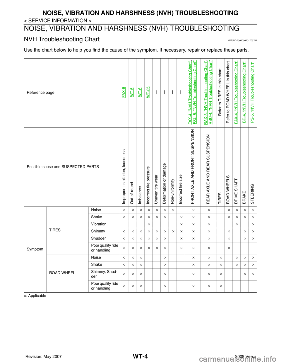
NVH Troubleshooting ChartINFOID:0000000001703747
Use the chart below to help you find the cause of the symptom. If necessary, repair or replace these parts.
×: ApplicableReference page
FAX-5WT-5
WT-6
WT-25—
—
—
—
FAX-4, "
NVH Troubleshooting Chart
",
FSU-5, "
NVH Troubleshooting Chart
"
RAX-3, "
NVH Troubleshooting Chart
",
RSU-4, "
NVH Troubleshooting Chart
"
Refer to TIRES in this chart
Refer to ROAD WHEEL in this chart
FAX-4, "
NVH Troubleshooting Chart
"
BR-4, "
NVH Troubleshooting Chart
"
PS-5, "
NVH Troubleshooting Chart
"
Possible cause and SUSPECTED PARTS
Improper installation, looseness
Out-of-round
Imbalance
Incorrect tire pressure
Uneven tire wear
Deformation or damage
Non-uniformity
Incorrect tire size
FRONT AXLE AND FRONT SUSPENSION
REAR AXLE AND REAR SUSPENSION
TIRES
ROAD WHEELS
DRIVE SHAFT
BRAKE
STEERING
SymptomTIRESNoise× ×××××× × × ××××
Shake× ××××× × × × ××××
Vibration××××××
Shimmy× ××××××× × × × ××
Shudder× ××××× × × × × ××
Poor quality ride
or handling× ××××× × × × ×
ROAD WHEELNoise× ×× × × × × ×××
Shake× ×× × × × × ×××
Shimmy, Shud-
der×××× ×××××
Poor quality ride
or handling××× × × × ×
Page 2755 of 2771

WW-22
< SERVICE INFORMATION >
FRONT WIPER AND WASHER SYSTEM
Removal and Installation of Front Wiper and Washer Switch
INFOID:0000000001704561
REMOVAL
1. Remove the steering column cover. Refer to IP-10 .
2. Disconnect the wiper and washer switch connector.
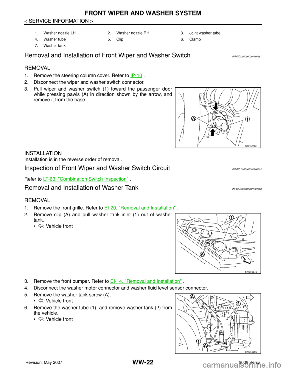
3. Pull wiper and washer switch (1) toward the passenger door
while pressing pawls (A) in direction shown by the arrow, and
remove it from the base.
INSTALLATION
Installation is in the reverse order of removal.
Inspection of Front Wiper and Washer Switch CircuitINFOID:0000000001704562
Refer to LT-63, "Combination Switch Inspection" .
Removal and Installation of Washer TankINFOID:0000000001704563
REMOVAL
1. Remove the front grille. Refer to EI-20, "Removal and Installation" .
2. Remove clip (A) and pull washer tank inlet (1) out of washer
tank.
• : Vehicle front
3. Remove the front bumper. Refer to EI-14, "
Removal and Installation" .
4. Disconnect the washer motor connector and washer fluid level sensor connector.
5. Remove the washer tank screw (A).
• : Vehicle front
6. Remove the washer tube (1), and remove washer tank (2) from
the vehicle.
• : Vehicle front
1. Washer nozzle LH 2. Washer nozzle RH 3. Joint washer tube
4. Washer tube 5. Clip 6. Clamp
7. Washer tank
SKIB5666E
SKIB5667E
SKIB5668E