2008 NISSAN TIIDA connector d2
[x] Cancel search: connector d2Page 1498 of 2771
EC-424
< SERVICE INFORMATION >
DTC P1217 ENGINE OVER TEMPERATURE
OK >> GO TO 6.
NG >> Replace cooling fan motor.
6.CHECK INTERMITTENT INCIDENT
Perform EC-136
.
OK or NG
OK >> Replace IPDM E/R. Refer to PG-26, "Removal and Installation of IPDM E/R".
NG >> Repair or replace harness or connector.
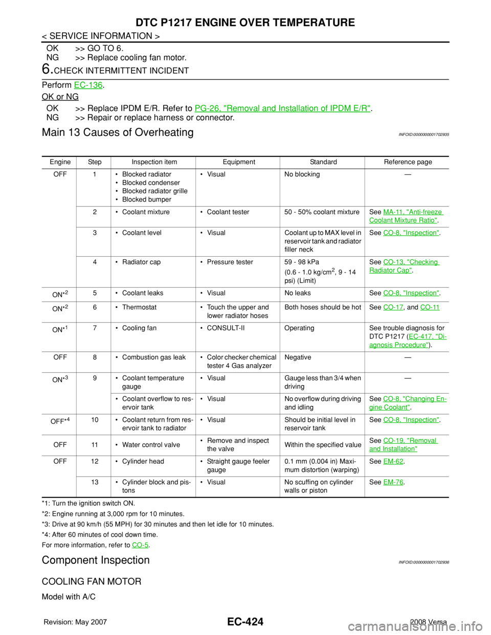
Main 13 Causes of OverheatingINFOID:0000000001702935
*1: Turn the ignition switch ON.
*2: Engine running at 3,000 rpm for 10 minutes.
*3: Drive at 90 km/h (55 MPH) for 30 minutes and then let idle for 10 minutes.
*4: After 60 minutes of cool down time.
For more information, refer to CO-5
.
Component InspectionINFOID:0000000001702936
COOLING FAN MOTOR
Model with A/C
Engine Step Inspection item Equipment Standard Reference page
OFF 1 • Blocked radiator
• Blocked condenser
• Blocked radiator grille
• Blocked bumper• Visual No blocking —
2 • Coolant mixture • Coolant tester 50 - 50% coolant mixture See MA-11, "
Anti-freeze
Coolant Mixture Ratio".
3 • Coolant level • Visual Coolant up to MAX level in
reservoir tank and radiator
filler neckSee CO-8, "
Inspection".
4 • Radiator cap • Pressure tester 59 - 98 kPa
(0.6 - 1.0 kg/cm
2, 9 - 14
psi) (Limit)See CO-13, "
Checking
Radiator Cap".
ON*
25 • Coolant leaks • Visual No leaks See CO-8, "Inspection".
ON*
26 • Thermostat • Touch the upper and
lower radiator hosesBoth hoses should be hot See CO-17, and CO-11
ON*17 • Cooling fan • CONSULT-II Operating See trouble diagnosis for
DTC P1217 (EC-417, "
Di-
agnosis Procedure").
OFF 8 • Combustion gas leak • Color checker chemical
tester 4 Gas analyzerNegative —
ON*
39 • Coolant temperature
gauge• Visual Gauge less than 3/4 when
driving—
• Coolant overflow to res-
ervoir tank• Visual No overflow during driving
and idlingSee CO-8, "
Changing En-
gine Coolant".
OFF*
410 • Coolant return from res-
ervoir tank to radiator• Visual Should be initial level in
reservoir tankSee CO-8, "Inspection".
OFF 11 • Water control valve• Remove and inspect
the valveWithin the specified valueSee CO-19, "
Removal
and Installation"
OFF 12 • Cylinder head • Straight gauge feeler
gauge0.1 mm (0.004 in) Maxi-
mum distortion (warping)See EM-62.
13 • Cylinder block and pis-
tons• Visual No scuffing on cylinder
walls or pistonSee EM-76
.
Page 1499 of 2771
DTC P1217 ENGINE OVER TEMPERATURE
EC-425
< SERVICE INFORMATION >
C
D
E
F
G
H
I
J
K
L
MA
EC
N
P O
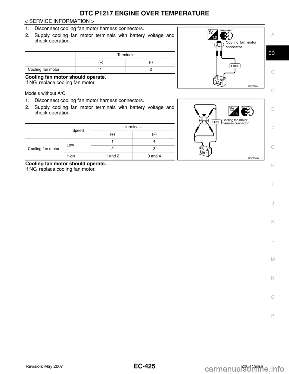
1. Disconnect cooling fan motor harness connectors.
2. Supply cooling fan motor terminals with battery voltage and
check operation.
Cooling fan motor should operate.
If NG, replace cooling fan motor.
Models without A/C
1. Disconnect cooling fan motor harness connectors.
2. Supply cooling fan motor terminals with battery voltage and
check operation.
Cooling fan motor should operate.
If NG, replace cooling fan motor.
Te r m i n a l s
(+) (-)
Cooling fan motor 1 2
SEF888V
Sp ee dterminals
(+) (−)
Cooling fan motorLow 14
23
High 1 and 2 3 and 4
SEF734W
Page 1506 of 2771
EC-432
< SERVICE INFORMATION >
DTC P1564 ASCD STEERING SWITCH
DTC P1564 ASCD STEERING SWITCH
Component DescriptionINFOID:0000000001702951
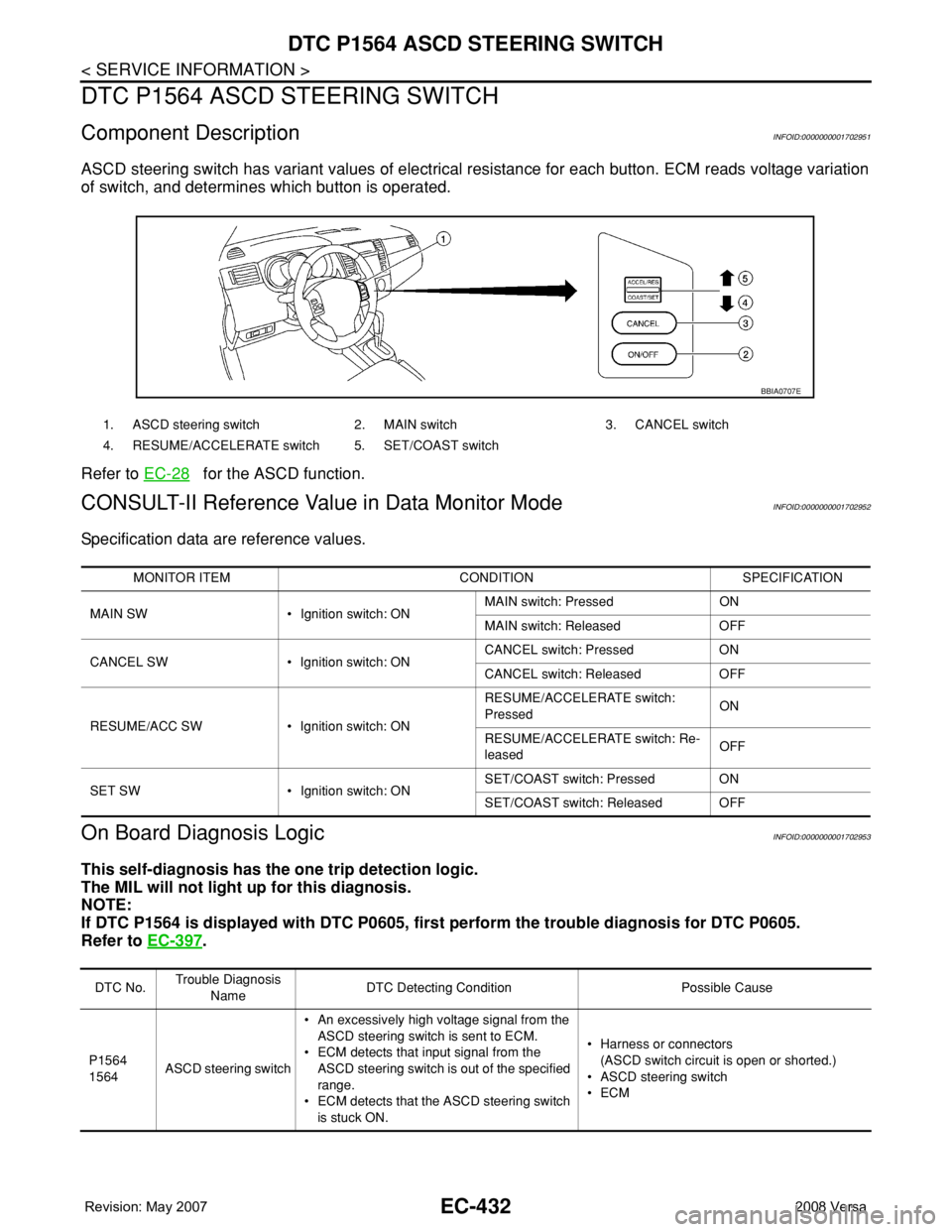
ASCD steering switch has variant values of electrical resistance for each button. ECM reads voltage variation
of switch, and determines which button is operated.
Refer to EC-28
for the ASCD function.
CONSULT-II Reference Value in Data Monitor ModeINFOID:0000000001702952
Specification data are reference values.
On Board Diagnosis LogicINFOID:0000000001702953
This self-diagnosis has the one trip detection logic.
The MIL will not light up for this diagnosis.
NOTE:
If DTC P1564 is displayed with DTC P0605, first perform the trouble diagnosis for DTC P0605.
Refer to EC-397
.
1. ASCD steering switch 2. MAIN switch 3. CANCEL switch
4. RESUME/ACCELERATE switch 5. SET/COAST switch
BBIA0707E
MONITOR ITEM CONDITION SPECIFICATION
MAIN SW • Ignition switch: ONMAIN switch: Pressed ON
MAIN switch: Released OFF
CANCEL SW • Ignition switch: ONCANCEL switch: Pressed ON
CANCEL switch: Released OFF
RESUME/ACC SW • Ignition switch: ONRESUME/ACCELERATE switch:
PressedON
RESUME/ACCELERATE switch: Re-
leasedOFF
SET SW • Ignition switch: ONSET/COAST switch: Pressed ON
SET/COAST switch: Released OFF
DTC No.Trouble Diagnosis
NameDTC Detecting Condition Possible Cause
P1564
1564ASCD steering switch• An excessively high voltage signal from the
ASCD steering switch is sent to ECM.
• ECM detects that input signal from the
ASCD steering switch is out of the specified
range.
• ECM detects that the ASCD steering switch
is stuck ON.• Harness or connectors
(ASCD switch circuit is open or shorted.)
•ASCD steering switch
•ECM
Page 1510 of 2771
EC-436
< SERVICE INFORMATION >
DTC P1564 ASCD STEERING SWITCH
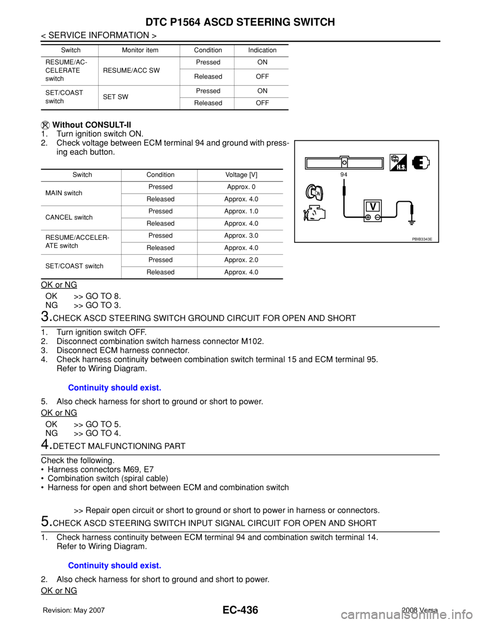
Without CONSULT-II
1. Turn ignition switch ON.
2. Check voltage between ECM terminal 94 and ground with press-
ing each button.
OK or NG
OK >> GO TO 8.
NG >> GO TO 3.
3.CHECK ASCD STEERING SWITCH GROUND CIRCUIT FOR OPEN AND SHORT
1. Turn ignition switch OFF.
2. Disconnect combination switch harness connector M102.
3. Disconnect ECM harness connector.
4. Check harness continuity between combination switch terminal 15 and ECM terminal 95.
Refer to Wiring Diagram.
5. Also check harness for short to ground or short to power.
OK or NG
OK >> GO TO 5.
NG >> GO TO 4.
4.DETECT MALFUNCTIONING PART
Check the following.
• Harness connectors M69, E7
• Combination switch (spiral cable)
• Harness for open and short between ECM and combination switch
>> Repair open circuit or short to ground or short to power in harness or connectors.
5.CHECK ASCD STEERING SWITCH INPUT SIGNAL CIRCUIT FOR OPEN AND SHORT
1. Check harness continuity between ECM terminal 94 and combination switch terminal 14.
Refer to Wiring Diagram.
2. Also check harness for short to ground and short to power.
OK or NG
RESUME/AC-
CELERATE
switchRESUME/ACC SWPressed ON
Released OFF
SET/COAST
switchSET SWPressed ON
Released OFF Switch Monitor item Condition Indication
Switch Condition Voltage [V]
MAIN switchPressed Approx. 0
Released Approx. 4.0
CANCEL switchPressed Approx. 1.0
Released Approx. 4.0
RESUME/ACCELER-
AT E s w i t c hPressed Approx. 3.0
Released Approx. 4.0
SET/COAST switchPressed Approx. 2.0
Released Approx. 4.0
PBIB3343E
Continuity should exist.
Continuity should exist.
Page 1511 of 2771
DTC P1564 ASCD STEERING SWITCH
EC-437
< SERVICE INFORMATION >
C
D
E
F
G
H
I
J
K
L
MA
EC
N
P O
OK >> GO TO 7.
NG >> GO TO 6.
6.DETECT MALFUNCTIONING PART
Check the following.
• Harness connectors M69, E7
• Combination switch (spiral cable)
• Harness for open and short between ECM and combination switch
>> Repair open circuit or short to ground or short to power in harness or connectors.
7.CHECK ASCD STEERING SWITCH
Refer to EC-437, "
Component Inspection".
OK or NG
OK >> GO TO 7.
NG >> Replace ASCD steering switch.
8.CHECK INTERMITTENT INCIDENT
Refer to EC-136
.
>>INSPECTION END
Component InspectionINFOID:0000000001702957
ASCD STEERING SWITCH
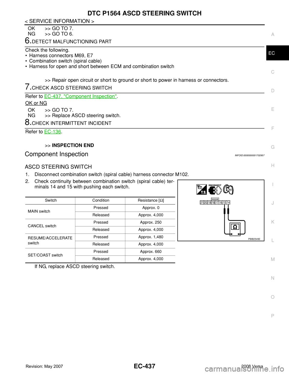
1. Disconnect combination switch (spiral cable) harness connector M102.
2. Check continuity between combination switch (spiral cable) ter-
minals 14 and 15 with pushing each switch.
If NG, replace ASCD steering switch.
Switch Condition Resistance [Ω]
MAIN switchPressed Approx. 0
Released Approx. 4,000
CANCEL switchPressed Approx. 250
Released Approx. 4,000
RESUME/ACCELERATE
switchPressed Approx. 1,480
Released Approx. 4,000
SET/COAST switchPressed Approx. 660
Released Approx. 4,000
PBIB2549E
Page 1512 of 2771
EC-438
< SERVICE INFORMATION >
DTC P1572 ASCD BRAKE SWITCH
DTC P1572 ASCD BRAKE SWITCH
Component DescriptionINFOID:0000000001702958
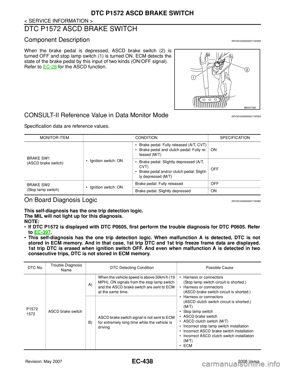
When the brake pedal is depressed, ASCD brake switch (2) is
turned OFF and stop lamp switch (1) is turned ON. ECM detects the
state of the brake pedal by this input of two kinds (ON/OFF signal).
Refer to EC-28
for the ASCD function.
CONSULT-II Reference Value in Data Monitor ModeINFOID:0000000001702959
Specification data are reference values.
On Board Diagnosis LogicINFOID:0000000001702960
This self-diagnosis has the one trip detection logic.
The MIL will not light up for this diagnosis.
NOTE:
•If DTC P1572 is displayed with DTC P0605, first perform the trouble diagnosis for DTC P0605. Refer
to EC-397
.
•This self-diagnosis has the one trip detection logic. When malfunction A is detected, DTC is not
stored in ECM memory. And in that case, 1st trip DTC and 1st trip freeze frame data are displayed.
1st trip DTC is erased when ignition switch OFF. And even when malfunction A is detected in two
consecutive trips, DTC is not stored in ECM memory.
BBIA0708E
MONITOR ITEM CONDITION SPECIFICATION
BRAKE SW1
(ASCD brake switch)• Ignition switch: ON• Brake pedal: Fully released (A/T, CVT)
• Brake pedal and clutch pedal: Fully re-
leased (M/T)ON
• Brake pedal: Slightly depressed (A/T,
CVT)
• Brake pedal and/or clutch pedal: Slight-
ly depressed (M/T)OFF
BRAKE SW2
(Stop lamp switch)• Ignition switch: ONBrake pedal: Fully released OFF
Brake pedal: Slightly depressed ON
DTC No.Trouble Diagnosis
NameDTC Detecting Condition Possible Cause
P1572
1572ASCD brake switchA)When the vehicle speed is above 30km/h (19
MPH), ON signals from the stop lamp switch
and the ASCD brake switch are sent to ECM
at the same time.• Harness or connectors
(Stop lamp switch circuit is shorted.)
• Harness or connectors
(ASCD brake switch circuit is shorted.)
• Harness or connectors
(ASCD clutch switch circuit is shorted.)
(M/T)
• Stop lamp switch
• ASCD brake switch
• ASCD clutch switch (M/T)
• Incorrect stop lamp switch installation
• Incorrect ASCD brake switch installation
• Incorrect ASCD clutch switch installation
(M/T)
•ECM B)ASCD brake switch signal is not sent to ECM
for extremely long time while the vehicle is
driving
Page 1516 of 2771
EC-442
< SERVICE INFORMATION >
DTC P1572 ASCD BRAKE SWITCH
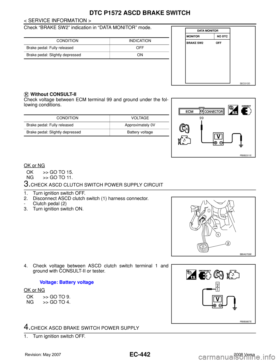
Check “BRAKE SW2” indication in “DATA MONITOR” mode.
Without CONSULT-II
Check voltage between ECM terminal 99 and ground under the fol-
lowing conditions.
OK or NG
OK >> GO TO 15.
NG >> GO TO 11.
3.CHECK ASCD CLUTCH SWITCH POWER SUPPLY CIRCUIT
1. Turn ignition switch OFF.
2. Disconnect ASCD clutch switch (1) harness connector.
- Clutch pedal (2)
3. Turn ignition switch ON.
4. Check voltage between ASCD clutch switch terminal 1 and
ground with CONSULT-II or tester.
OK or NG
OK >> GO TO 9.
NG >> GO TO 4.
4.CHECK ASCD BRAKE SWITCH POWER SUPPLY
1. Turn ignition switch OFF.
CONDITION INDICATION
Brake pedal: Fully released OFF
Brake pedal: Slightly depressed ON
SEC013D
CONDITION VOLTAGE
Brake pedal: Fully released Approximately 0V
Brake pedal: Slightly depressed Battery voltage
PBIB0311E
BBIA0709E
Voltage: Battery voltage
PBIB0857E
Page 1517 of 2771
DTC P1572 ASCD BRAKE SWITCH
EC-443
< SERVICE INFORMATION >
C
D
E
F
G
H
I
J
K
L
MA
EC
N
P O
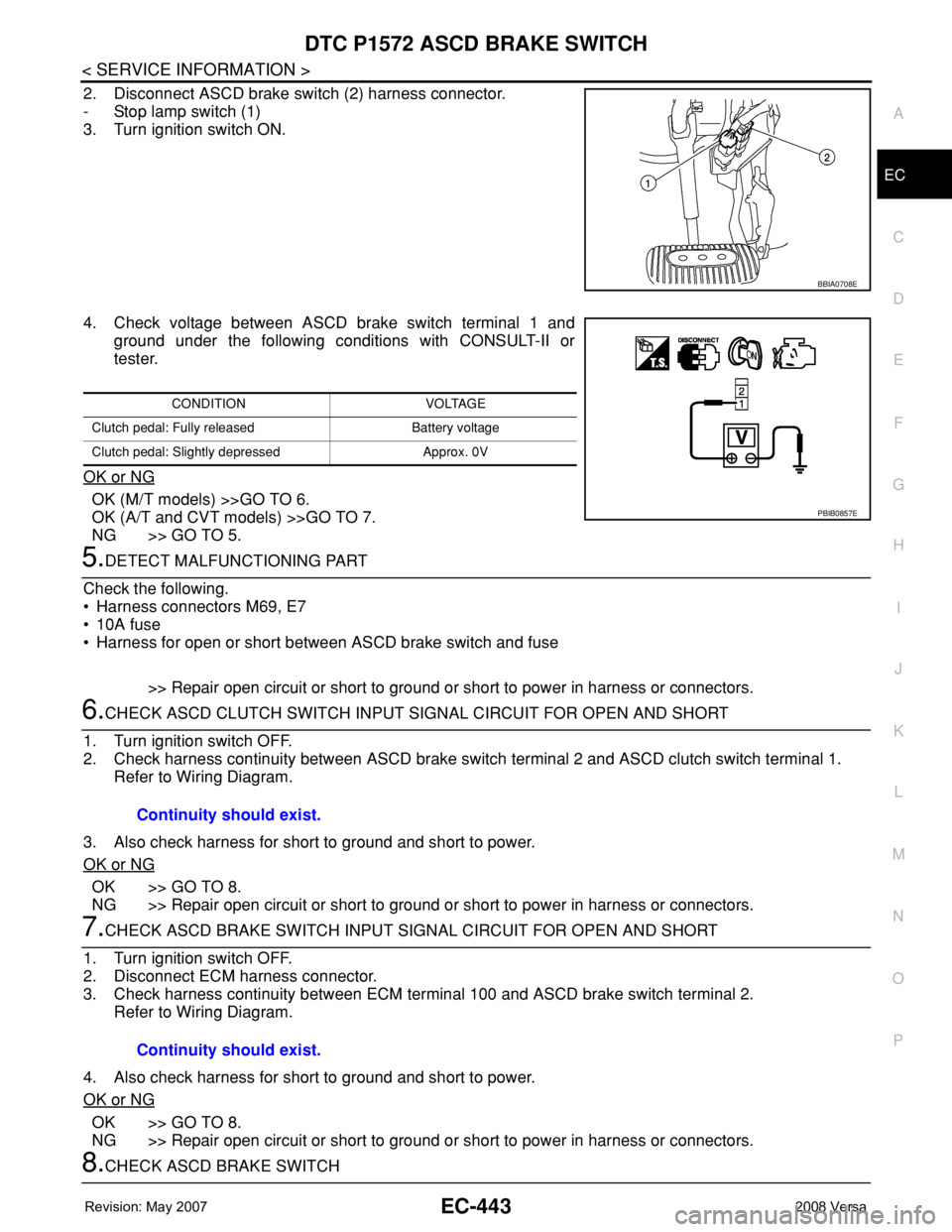
2. Disconnect ASCD brake switch (2) harness connector.
- Stop lamp switch (1)
3. Turn ignition switch ON.
4. Check voltage between ASCD brake switch terminal 1 and
ground under the following conditions with CONSULT-II or
tester.
OK or NG
OK (M/T models) >>GO TO 6.
OK (A/T and CVT models) >>GO TO 7.
NG >> GO TO 5.
5.DETECT MALFUNCTIONING PART
Check the following.
• Harness connectors M69, E7
• 10A fuse
• Harness for open or short between ASCD brake switch and fuse
>> Repair open circuit or short to ground or short to power in harness or connectors.
6.CHECK ASCD CLUTCH SWITCH INPUT SIGNAL CIRCUIT FOR OPEN AND SHORT
1. Turn ignition switch OFF.
2. Check harness continuity between ASCD brake switch terminal 2 and ASCD clutch switch terminal 1.
Refer to Wiring Diagram.
3. Also check harness for short to ground and short to power.
OK or NG
OK >> GO TO 8.
NG >> Repair open circuit or short to ground or short to power in harness or connectors.
7.CHECK ASCD BRAKE SWITCH INPUT SIGNAL CIRCUIT FOR OPEN AND SHORT
1. Turn ignition switch OFF.
2. Disconnect ECM harness connector.
3. Check harness continuity between ECM terminal 100 and ASCD brake switch terminal 2.
Refer to Wiring Diagram.
4. Also check harness for short to ground and short to power.
OK or NG
OK >> GO TO 8.
NG >> Repair open circuit or short to ground or short to power in harness or connectors.
8.CHECK ASCD BRAKE SWITCH
BBIA0708E
CONDITION VOLTAGE
Clutch pedal: Fully released Battery voltage
Clutch pedal: Slightly depressed Approx. 0V
PBIB0857E
Continuity should exist.
Continuity should exist.