2008 NISSAN TIIDA connector d2
[x] Cancel search: connector d2Page 1381 of 2771
DTC P0340 CMP SENSOR (PHASE)
EC-307
< SERVICE INFORMATION >
C
D
E
F
G
H
I
J
K
L
MA
EC
N
P O
Refer to EC-307, "Component Inspection".
OK or NG
OK >> GO TO 7.
NG >> Replace camshaft position sensor (PHASE).
7.CHECK CAMSHAFT (INTAKE)
Check the following.
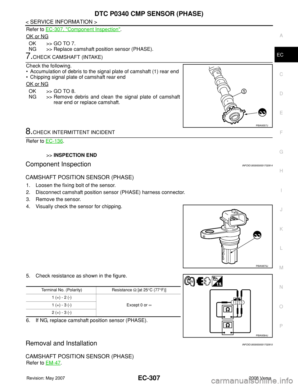
• Accumulation of debris to the signal plate of camshaft (1) rear end
• Chipping signal plate of camshaft rear end
OK or NG
OK >> GO TO 8.
NG >> Remove debris and clean the signal plate of camshaft
rear end or replace camshaft.
8.CHECK INTERMITTENT INCIDENT
Refer to EC-136
.
>>INSPECTION END
Component InspectionINFOID:0000000001702814
CAMSHAFT POSITION SENSOR (PHASE)
1. Loosen the fixing bolt of the sensor.
2. Disconnect camshaft position sensor (PHASE) harness connector.
3. Remove the sensor.
4. Visually check the sensor for chipping.
5. Check resistance as shown in the figure.
6. If NG, replace camshaft position sensor (PHASE).
Removal and InstallationINFOID:0000000001702815
CAMSHAFT POSITION SENSOR (PHASE)
Refer to EM-47.
PBIA9557J
PBIA9876J
Terminal No. (Polarity) Resistance Ω [at 25°C (77°F)]
1 (+) - 2 (-)
Except 0 or ∞ 1 (+) - 3 (-)
2 (+) - 3 (-)
PBIA9584J
Page 1384 of 2771
EC-310
< SERVICE INFORMATION >
DTC P0420 THREE WAY CATALYST FUNCTION
Diagnosis Procedure
INFOID:0000000001702819
1.CHECK EXHAUST SYSTEM
Visually check exhaust tubes and muffler for dent.
OK or NG
OK >> GO TO 2.
NG >> Repair or replace.
2.CHECK EXHAUST GAS LEAK
1. Start engine and run it at idle.
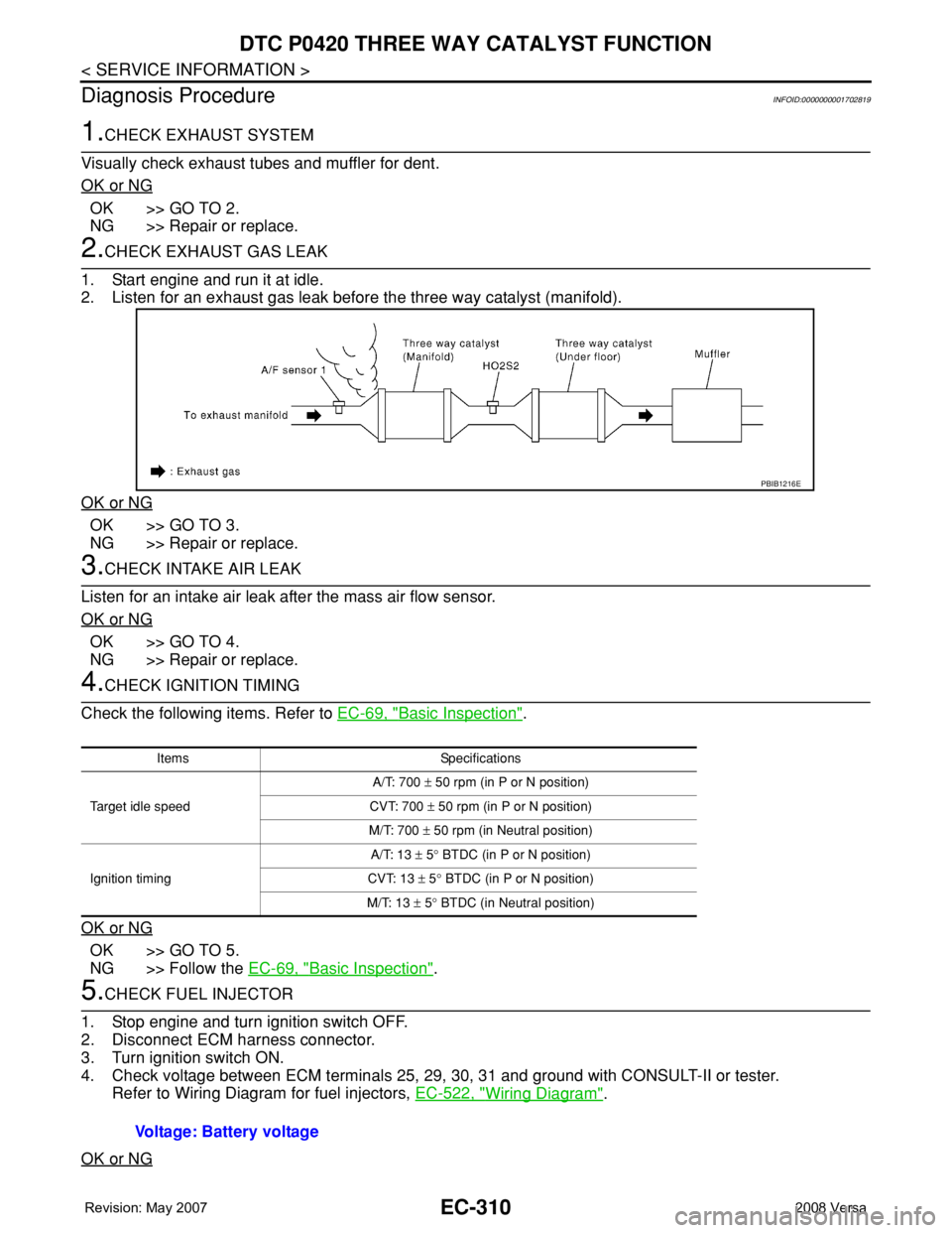
2. Listen for an exhaust gas leak before the three way catalyst (manifold).
OK or NG
OK >> GO TO 3.
NG >> Repair or replace.
3.CHECK INTAKE AIR LEAK
Listen for an intake air leak after the mass air flow sensor.
OK or NG
OK >> GO TO 4.
NG >> Repair or replace.
4.CHECK IGNITION TIMING
Check the following items. Refer to EC-69, "
Basic Inspection".
OK or NG
OK >> GO TO 5.
NG >> Follow the EC-69, "
Basic Inspection".
5.CHECK FUEL INJECTOR
1. Stop engine and turn ignition switch OFF.
2. Disconnect ECM harness connector.
3. Turn ignition switch ON.
4. Check voltage between ECM terminals 25, 29, 30, 31 and ground with CONSULT-II or tester.
Refer to Wiring Diagram for fuel injectors, EC-522, "
Wiring Diagram".
OK or NG
PBIB1216E
Items Specifications
Target idle speedA/T: 700 ± 50 rpm (in P or N position)
CVT: 700 ± 50 rpm (in P or N position)
M/T: 700 ± 50 rpm (in Neutral position)
Ignition timingA/T: 13 ± 5° BTDC (in P or N position)
CVT: 13 ± 5° BTDC (in P or N position)
M/T: 13 ± 5° BTDC (in Neutral position)
Voltage: Battery voltage
Page 1385 of 2771
DTC P0420 THREE WAY CATALYST FUNCTION
EC-311
< SERVICE INFORMATION >
C
D
E
F
G
H
I
J
K
L
MA
EC
N
P O
OK >> GO TO 6.
NG >> Perform EC-523, "
Diagnosis Procedure".
6.CHECK FUNCTION OF IGNITION COIL-I
CAUTION:
Do the following procedure in the place where ventilation is good without the combustible.
1. Turn ignition switch OFF.
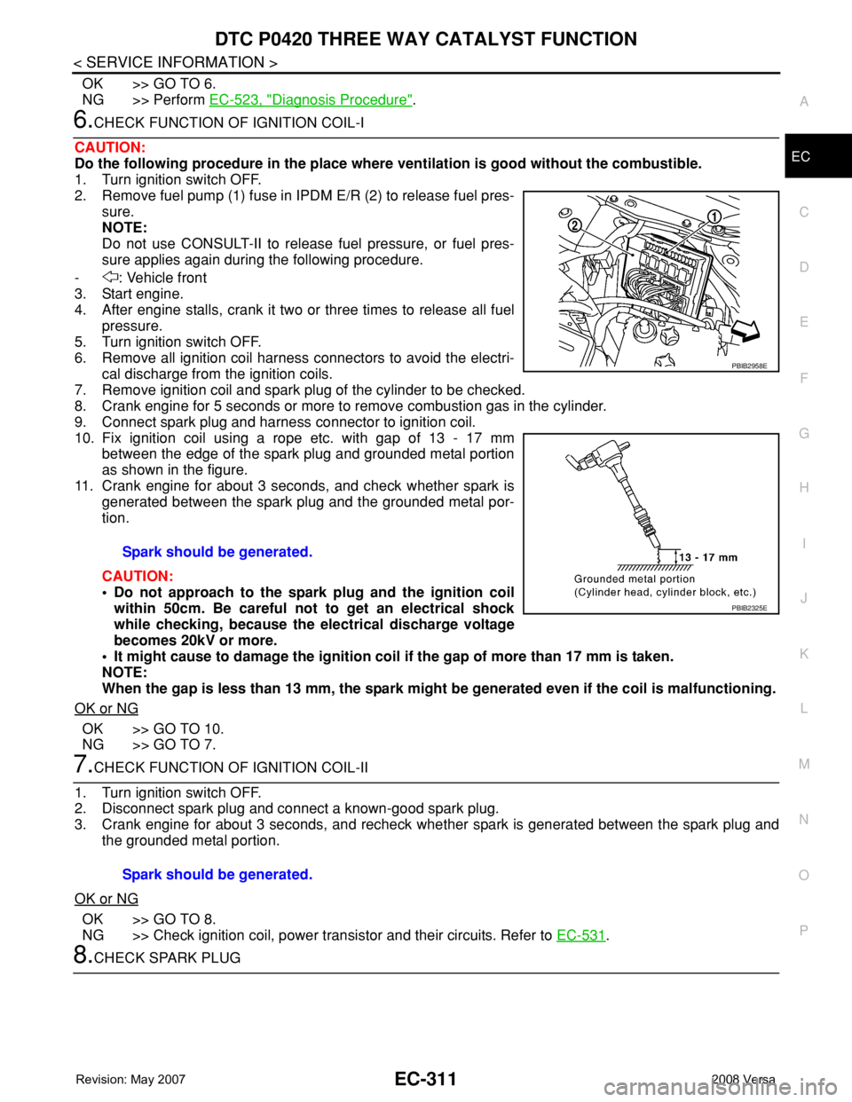
2. Remove fuel pump (1) fuse in IPDM E/R (2) to release fuel pres-
sure.
NOTE:
Do not use CONSULT-II to release fuel pressure, or fuel pres-
sure applies again during the following procedure.
- : Vehicle front
3. Start engine.
4. After engine stalls, crank it two or three times to release all fuel
pressure.
5. Turn ignition switch OFF.
6. Remove all ignition coil harness connectors to avoid the electri-
cal discharge from the ignition coils.
7. Remove ignition coil and spark plug of the cylinder to be checked.
8. Crank engine for 5 seconds or more to remove combustion gas in the cylinder.
9. Connect spark plug and harness connector to ignition coil.
10. Fix ignition coil using a rope etc. with gap of 13 - 17 mm
between the edge of the spark plug and grounded metal portion
as shown in the figure.
11. Crank engine for about 3 seconds, and check whether spark is
generated between the spark plug and the grounded metal por-
tion.
CAUTION:
• Do not approach to the spark plug and the ignition coil
within 50cm. Be careful not to get an electrical shock
while checking, because the electrical discharge voltage
becomes 20kV or more.
• It might cause to damage the ignition coil if the gap of more than 17 mm is taken.
NOTE:
When the gap is less than 13 mm, the spark might be generated even if the coil is malfunctioning.
OK or NG
OK >> GO TO 10.
NG >> GO TO 7.
7.CHECK FUNCTION OF IGNITION COIL-II
1. Turn ignition switch OFF.
2. Disconnect spark plug and connect a known-good spark plug.
3. Crank engine for about 3 seconds, and recheck whether spark is generated between the spark plug and
the grounded metal portion.
OK or NG
OK >> GO TO 8.
NG >> Check ignition coil, power transistor and their circuits. Refer to EC-531
.
8.CHECK SPARK PLUGSpark should be generated.
PBIB2958E
PBIB2325E
Spark should be generated.
Page 1386 of 2771
EC-312
< SERVICE INFORMATION >
DTC P0420 THREE WAY CATALYST FUNCTION
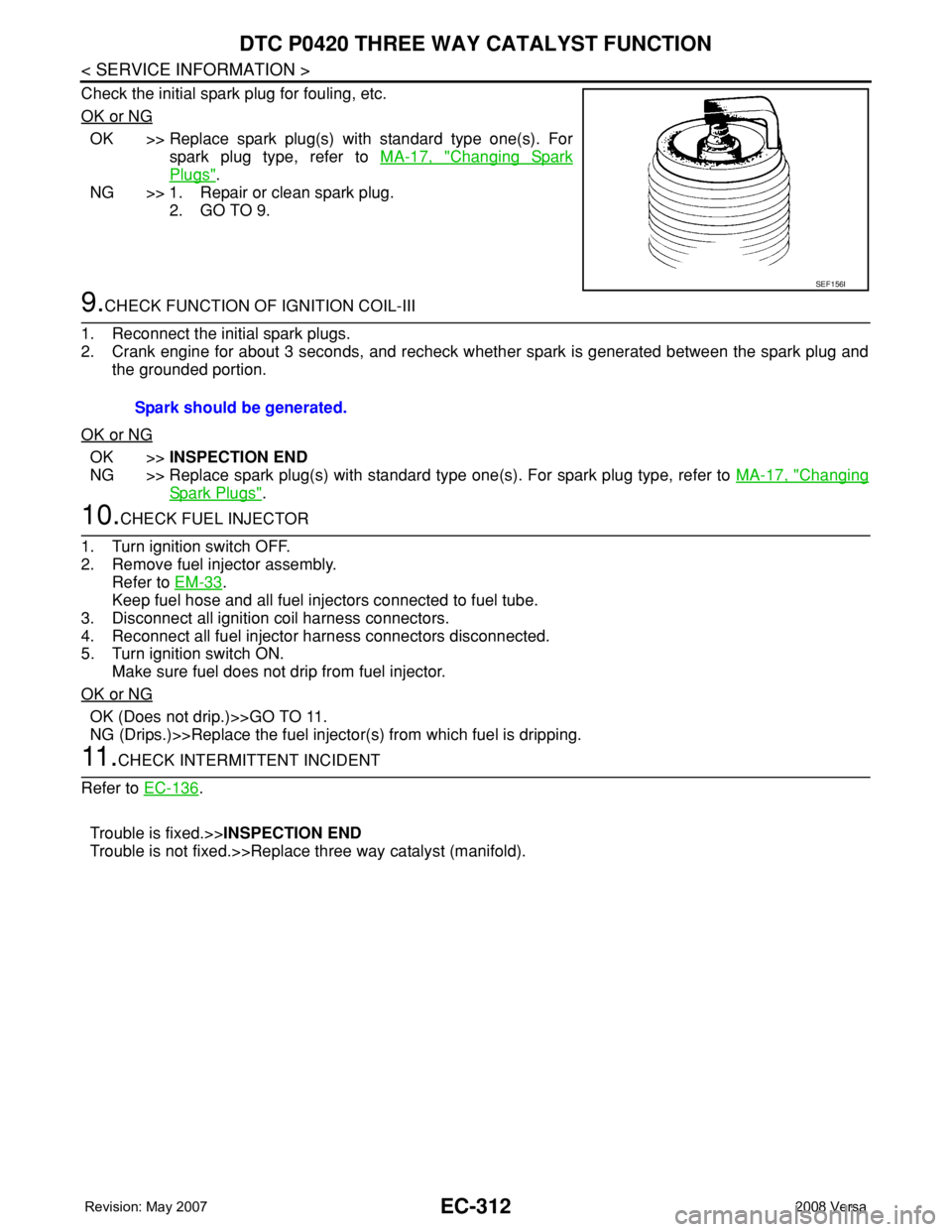
Check the initial spark plug for fouling, etc.
OK or NG
OK >> Replace spark plug(s) with standard type one(s). For
spark plug type, refer to MA-17, "
Changing Spark
Plugs".
NG >> 1. Repair or clean spark plug.
2. GO TO 9.
9.CHECK FUNCTION OF IGNITION COIL-III
1. Reconnect the initial spark plugs.
2. Crank engine for about 3 seconds, and recheck whether spark is generated between the spark plug and
the grounded portion.
OK or NG
OK >>INSPECTION END
NG >> Replace spark plug(s) with standard type one(s). For spark plug type, refer to MA-17, "
Changing
Spark Plugs".
10.CHECK FUEL INJECTOR
1. Turn ignition switch OFF.
2. Remove fuel injector assembly.
Refer to EM-33
.
Keep fuel hose and all fuel injectors connected to fuel tube.
3. Disconnect all ignition coil harness connectors.
4. Reconnect all fuel injector harness connectors disconnected.
5. Turn ignition switch ON.
Make sure fuel does not drip from fuel injector.
OK or NG
OK (Does not drip.)>>GO TO 11.
NG (Drips.)>>Replace the fuel injector(s) from which fuel is dripping.
11 .CHECK INTERMITTENT INCIDENT
Refer to EC-136
.
Trouble is fixed.>>INSPECTION END
Trouble is not fixed.>>Replace three way catalyst (manifold).
SEF156I
Spark should be generated.
Page 1390 of 2771
EC-316
< SERVICE INFORMATION >
DTC P0441 EVAP CONTROL SYSTEM
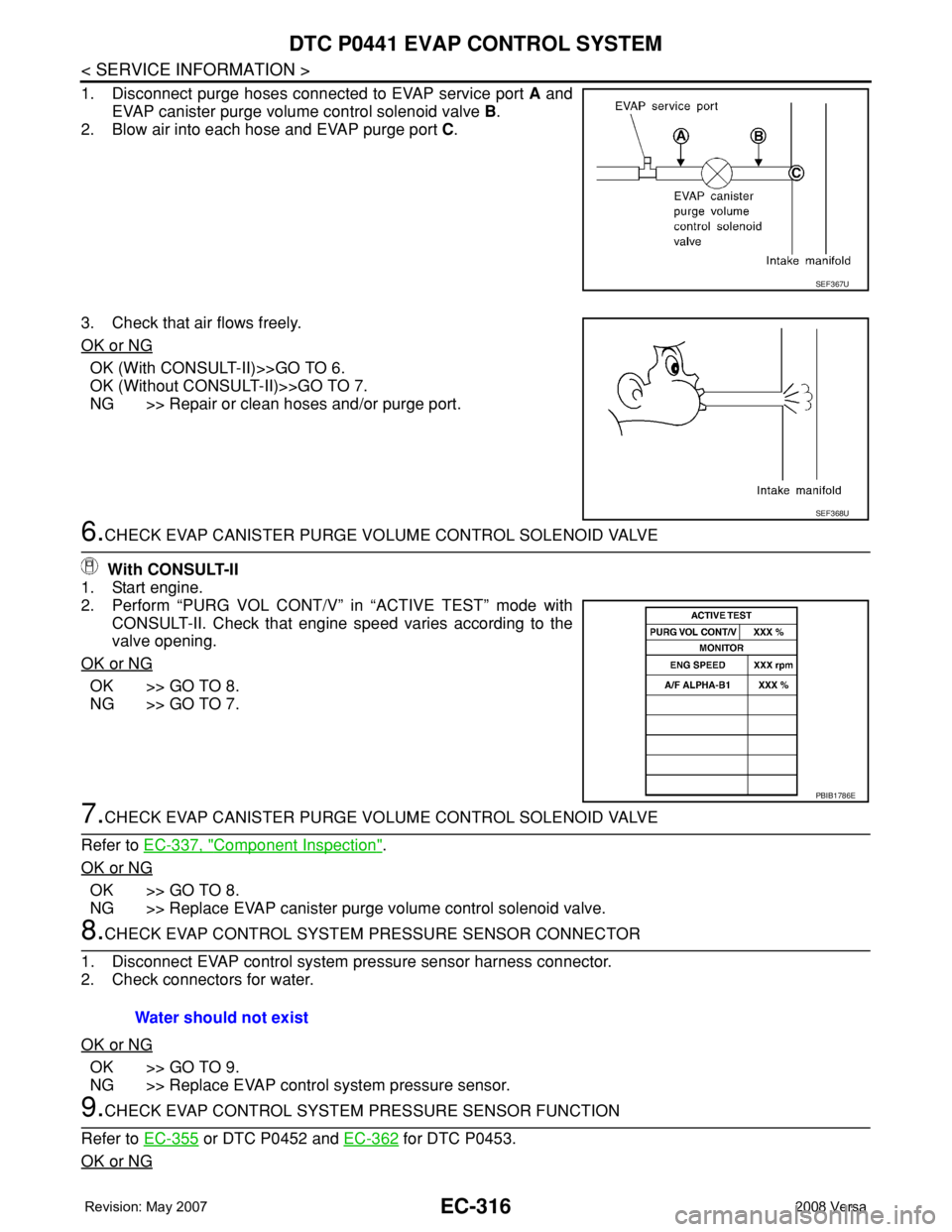
1. Disconnect purge hoses connected to EVAP service port A and
EVAP canister purge volume control solenoid valve B.
2. Blow air into each hose and EVAP purge port C.
3. Check that air flows freely.
OK or NG
OK (With CONSULT-II)>>GO TO 6.
OK (Without CONSULT-II)>>GO TO 7.
NG >> Repair or clean hoses and/or purge port.
6.CHECK EVAP CANISTER PURGE VOLUME CONTROL SOLENOID VALVE
With CONSULT-II
1. Start engine.
2. Perform “PURG VOL CONT/V” in “ACTIVE TEST” mode with
CONSULT-II. Check that engine speed varies according to the
valve opening.
OK or NG
OK >> GO TO 8.
NG >> GO TO 7.
7.CHECK EVAP CANISTER PURGE VOLUME CONTROL SOLENOID VALVE
Refer to EC-337, "
Component Inspection".
OK or NG
OK >> GO TO 8.
NG >> Replace EVAP canister purge volume control solenoid valve.
8.CHECK EVAP CONTROL SYSTEM PRESSURE SENSOR CONNECTOR
1. Disconnect EVAP control system pressure sensor harness connector.
2. Check connectors for water.
OK or NG
OK >> GO TO 9.
NG >> Replace EVAP control system pressure sensor.
9.CHECK EVAP CONTROL SYSTEM PRESSURE SENSOR FUNCTION
Refer to EC-355
or DTC P0452 and EC-362 for DTC P0453.
OK or NG
SEF367U
SEF368U
PBIB1786E
Water should not exist
Page 1402 of 2771
EC-328
< SERVICE INFORMATION >
DTC P0443 EVAP CANISTER PURGE VOLUME CONTROL SOLENOID VALVE
Do not use ECM ground terminals when measuring input/output voltage. Doing so may result in dam-
age to the ECM's transistor. Use a ground other than ECM terminals, such as the ground.
: Average voltage for pulse signal (Actual pulse signal can be confirmed by oscilloscope.)
Diagnosis ProcedureINFOID:0000000001702833
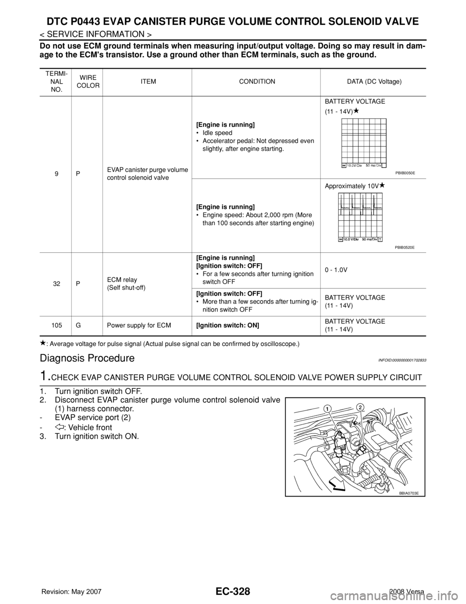
1.CHECK EVAP CANISTER PURGE VOLUME CONTROL SOLENOID VALVE POWER SUPPLY CIRCUIT
1. Turn ignition switch OFF.
2. Disconnect EVAP canister purge volume control solenoid valve
(1) harness connector.
- EVAP service port (2)
- : Vehicle front
3. Turn ignition switch ON.
TERMI-
NAL
NO.WIRE
COLORITEM CONDITION DATA (DC Voltage)
9PEVAP canister purge volume
control solenoid valve[Engine is running]
• Idle speed
• Accelerator pedal: Not depressed even
slightly, after engine starting.BATTERY VOLTAGE
(11 - 14V)
[Engine is running]
• Engine speed: About 2,000 rpm (More
than 100 seconds after starting engine)Approximately 10V
32 PECM relay
(Self shut-off)[Engine is running]
[Ignition switch: OFF]
• For a few seconds after turning ignition
switch OFF0 - 1.0V
[Ignition switch: OFF]
• More than a few seconds after turning ig-
nition switch OFFBATTERY VOLTAGE
(11 - 14V)
105 G Power supply for ECM[Ignition switch: ON]BATTERY VOLTAGE
(11 - 14V)
PBIB0050E
PBIB0520E
BBIA0703E
Page 1403 of 2771
DTC P0443 EVAP CANISTER PURGE VOLUME CONTROL SOLENOID VALVE
EC-329
< SERVICE INFORMATION >
C
D
E
F
G
H
I
J
K
L
MA
EC
N
P O
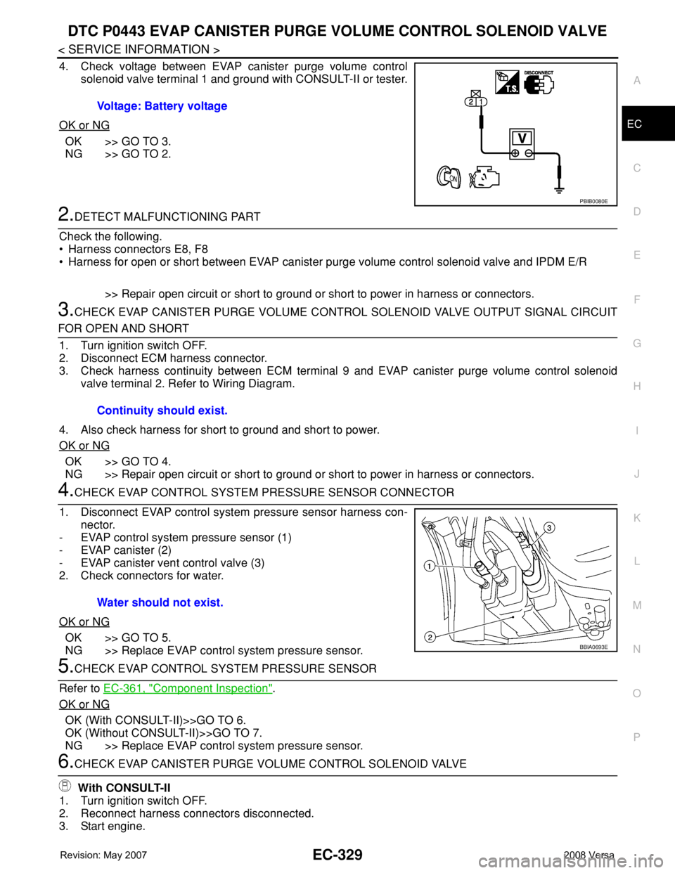
4. Check voltage between EVAP canister purge volume control
solenoid valve terminal 1 and ground with CONSULT-II or tester.
OK or NG
OK >> GO TO 3.
NG >> GO TO 2.
2.DETECT MALFUNCTIONING PART
Check the following.
• Harness connectors E8, F8
• Harness for open or short between EVAP canister purge volume control solenoid valve and IPDM E/R
>> Repair open circuit or short to ground or short to power in harness or connectors.
3.CHECK EVAP CANISTER PURGE VOLUME CONTROL SOLENOID VALVE OUTPUT SIGNAL CIRCUIT
FOR OPEN AND SHORT
1. Turn ignition switch OFF.
2. Disconnect ECM harness connector.
3. Check harness continuity between ECM terminal 9 and EVAP canister purge volume control solenoid
valve terminal 2. Refer to Wiring Diagram.
4. Also check harness for short to ground and short to power.
OK or NG
OK >> GO TO 4.
NG >> Repair open circuit or short to ground or short to power in harness or connectors.
4.CHECK EVAP CONTROL SYSTEM PRESSURE SENSOR CONNECTOR
1. Disconnect EVAP control system pressure sensor harness con-
nector.
- EVAP control system pressure sensor (1)
- EVAP canister (2)
- EVAP canister vent control valve (3)
2. Check connectors for water.
OK or NG
OK >> GO TO 5.
NG >> Replace EVAP control system pressure sensor.
5.CHECK EVAP CONTROL SYSTEM PRESSURE SENSOR
Refer to EC-361, "
Component Inspection".
OK or NG
OK (With CONSULT-II)>>GO TO 6.
OK (Without CONSULT-II)>>GO TO 7.
NG >> Replace EVAP control system pressure sensor.
6.CHECK EVAP CANISTER PURGE VOLUME CONTROL SOLENOID VALVE
With CONSULT-II
1. Turn ignition switch OFF.
2. Reconnect harness connectors disconnected.
3. Start engine.Voltage: Battery voltage
PBIB0080E
Continuity should exist.
Water should not exist.
BBIA0693E
Page 1407 of 2771
DTC P0444, P0445 EVAP CANISTER PURGE VOLUME CONTROL SOLENOID
VALVE
EC-333
< SERVICE INFORMATION >
C
D
E
F
G
H
I
J
K
L
MA
EC
N
P O
On Board Diagnosis LogicINFOID:0000000001702838
DTC Confirmation ProcedureINFOID:0000000001702839
NOTE:
If DTC Confirmation Procedure has been previously conducted, always turn ignition switch OFF and wait at
least 10 seconds before conducting the next test.
TESTING CONDITION:
Before performing the following procedure, confirm battery voltage is more than 11V at idle.
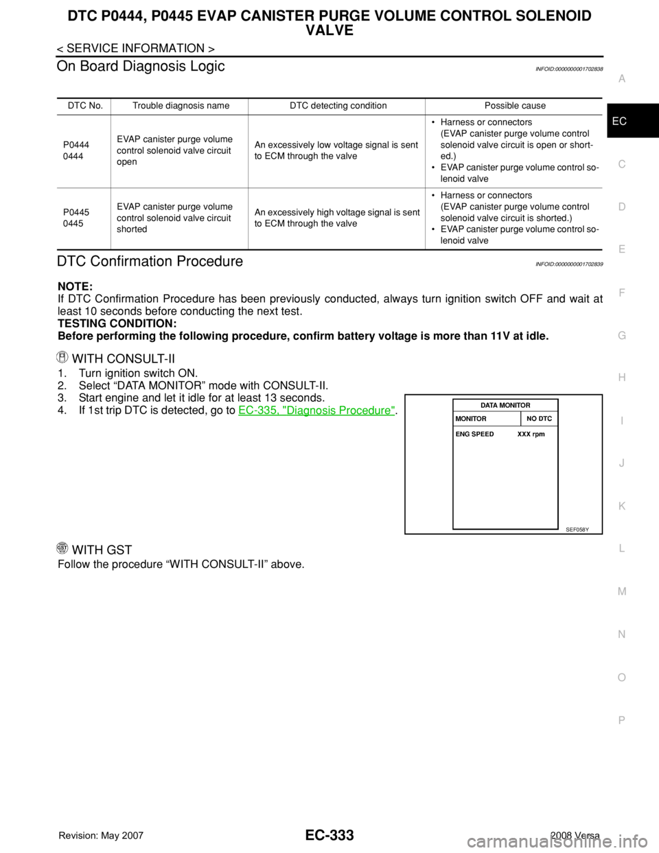
WITH CONSULT-II
1. Turn ignition switch ON.
2. Select “DATA MONITOR” mode with CONSULT-II.
3. Start engine and let it idle for at least 13 seconds.
4. If 1st trip DTC is detected, go to EC-335, "
Diagnosis Procedure".
WITH GST
Follow the procedure “WITH CONSULT-II” above.
DTC No. Trouble diagnosis name DTC detecting condition Possible cause
P0444
0444EVAP canister purge volume
control solenoid valve circuit
openAn excessively low voltage signal is sent
to ECM through the valve• Harness or connectors
(EVAP canister purge volume control
solenoid valve circuit is open or short-
ed.)
• EVAP canister purge volume control so-
lenoid valve
P0445
0445EVAP canister purge volume
control solenoid valve circuit
shortedAn excessively high voltage signal is sent
to ECM through the valve• Harness or connectors
(EVAP canister purge volume control
solenoid valve circuit is shorted.)
• EVAP canister purge volume control so-
lenoid valve
SEF058Y