2008 NISSAN TIIDA check engine
[x] Cancel search: check enginePage 2599 of 2771
STARTING SYSTEM
SC-17
< SERVICE INFORMATION >
C
D
E
F
G
H
I
J
L
MA
B
SC
N
O
P
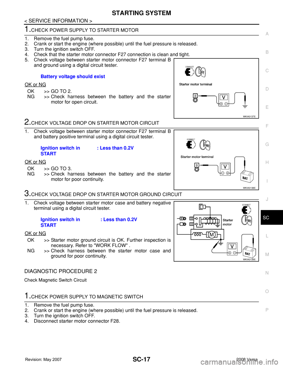
1.CHECK POWER SUPPLY TO STARTER MOTOR
1. Remove the fuel pump fuse.
2. Crank or start the engine (where possible) until the fuel pressure is released.
3. Turn the ignition switch OFF.
4. Check that the starter motor connector F27 connection is clean and tight.
5. Check voltage between starter motor connector F27 terminal B
and ground using a digital circuit tester.
OK or NG
OK >> GO TO 2.
NG >> Check harness between the battery and the starter
motor for open circuit.
2.CHECK VOLTAGE DROP ON STARTER MOTOR CIRCUIT
1. Check voltage between starter motor connector F27 terminal B
and battery positive terminal using a digital circuit tester.
OK or NG
OK >> GO TO 3.
NG >> Check harness between the battery and the starter
motor for poor continuity.
3.CHECK VOLTAGE DROP ON STARTER MOTOR GROUND CIRCUIT
1. Check voltage between starter motor case and battery negative
terminal using a digital circuit tester.
OK or NG
OK >> Starter motor ground circuit is OK. Further inspection is
necessary. Refer to "WORK FLOW" .
NG >> Check harness between the starter motor case and
ground for poor continuity.
DIAGNOSTIC PROCEDURE 2
Check Magnetic Switch Circuit
1.CHECK POWER SUPPLY TO MAGNETIC SWITCH
1. Remove the fuel pump fuse.
2. Crank or start the engine (where possible) until the fuel pressure is released.
3. Turn the ignition switch OFF.
4. Disconnect starter motor connector F28.Battery voltage should exist
WKIA0137E
Ignition switch in
START: Less than 0.2V
WKIA0138E
Ignition switch in
START: Less than 0.2V
WKIA0139E
Page 2600 of 2771
SC-18
< SERVICE INFORMATION >
STARTING SYSTEM
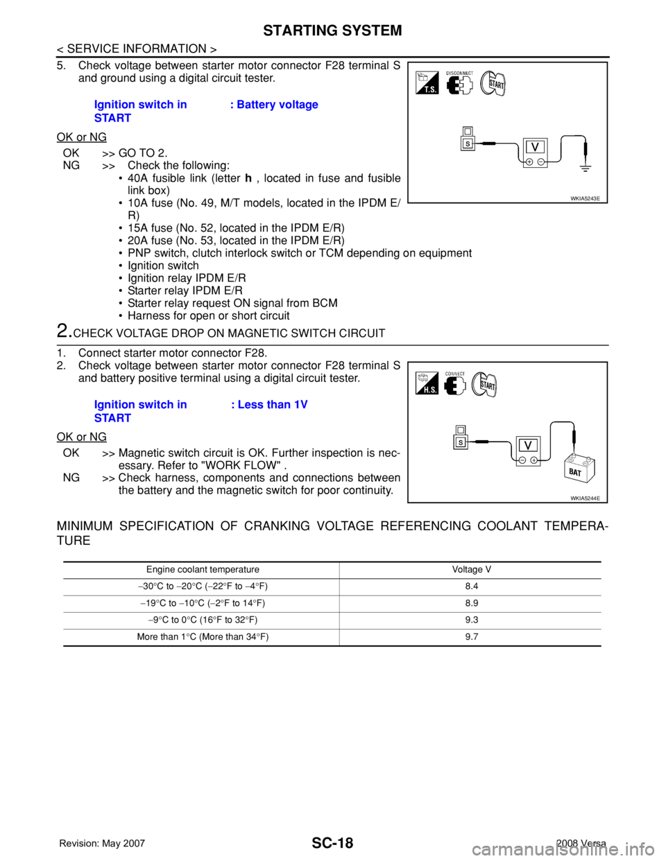
5. Check voltage between starter motor connector F28 terminal S
and ground using a digital circuit tester.
OK or NG
OK >> GO TO 2.
NG >> Check the following:
• 40A fusible link (letter h , located in fuse and fusible
link box)
• 10A fuse (No. 49, M/T models, located in the IPDM E/
R)
• 15A fuse (No. 52, located in the IPDM E/R)
• 20A fuse (No. 53, located in the IPDM E/R)
• PNP switch, clutch interlock switch or TCM depending on equipment
• Ignition switch
• Ignition relay IPDM E/R
• Starter relay IPDM E/R
• Starter relay request ON signal from BCM
• Harness for open or short circuit
2.CHECK VOLTAGE DROP ON MAGNETIC SWITCH CIRCUIT
1. Connect starter motor connector F28.
2. Check voltage between starter motor connector F28 terminal S
and battery positive terminal using a digital circuit tester.
OK or NG
OK >> Magnetic switch circuit is OK. Further inspection is nec-
essary. Refer to "WORK FLOW" .
NG >> Check harness, components and connections between
the battery and the magnetic switch for poor continuity.
MINIMUM SPECIFICATION OF CRANKING VOLTAGE REFERENCING COOLANT TEMPERA-
TURE
Ignition switch in
START: Battery voltage
WKIA5243E
Ignition switch in
START: Less than 1V
WKIA5244E
Engine coolant temperature Voltage V
−30°C to −20°C (−22°F to −4°F) 8.4
−19°C to −10°C (−2°F to 14°F) 8.9
−9°C to 0°C (16°F to 32°F) 9.3
More than 1°C (More than 34°F) 9.7
Page 2605 of 2771
CHARGING SYSTEM
SC-23
< SERVICE INFORMATION >
C
D
E
F
G
H
I
J
L
MA
B
SC
N
O
P
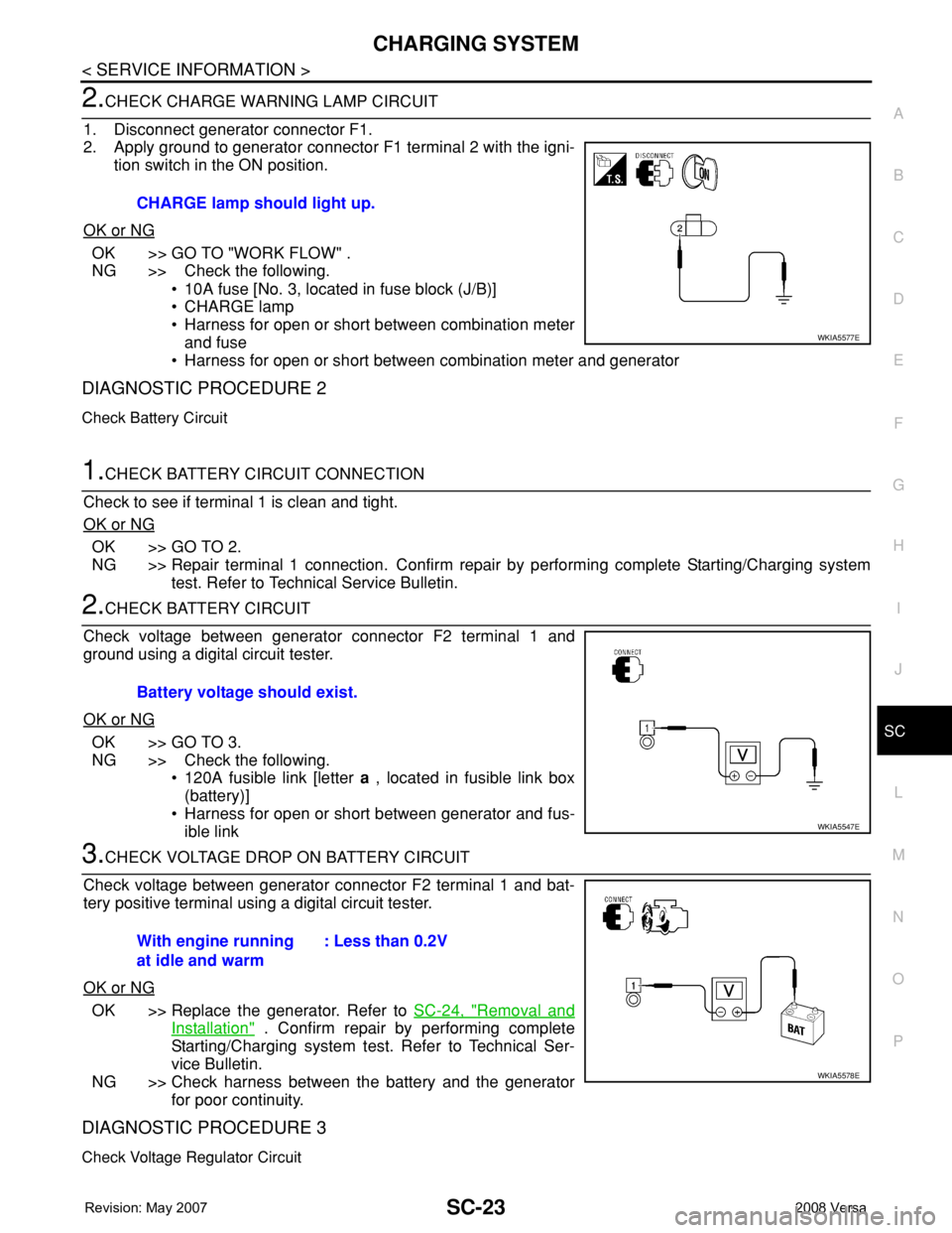
2.CHECK CHARGE WARNING LAMP CIRCUIT
1. Disconnect generator connector F1.
2. Apply ground to generator connector F1 terminal 2 with the igni-
tion switch in the ON position.
OK or NG
OK >> GO TO "WORK FLOW" .
NG >> Check the following.
• 10A fuse [No. 3, located in fuse block (J/B)]
• CHARGE lamp
• Harness for open or short between combination meter
and fuse
• Harness for open or short between combination meter and generator
DIAGNOSTIC PROCEDURE 2
Check Battery Circuit
1.CHECK BATTERY CIRCUIT CONNECTION
Check to see if terminal 1 is clean and tight.
OK or NG
OK >> GO TO 2.
NG >> Repair terminal 1 connection. Confirm repair by performing complete Starting/Charging system
test. Refer to Technical Service Bulletin.
2.CHECK BATTERY CIRCUIT
Check voltage between generator connector F2 terminal 1 and
ground using a digital circuit tester.
OK or NG
OK >> GO TO 3.
NG >> Check the following.
• 120A fusible link [letter a , located in fusible link box
(battery)]
• Harness for open or short between generator and fus-
ible link
3.CHECK VOLTAGE DROP ON BATTERY CIRCUIT
Check voltage between generator connector F2 terminal 1 and bat-
tery positive terminal using a digital circuit tester.
OK or NG
OK >> Replace the generator. Refer to SC-24, "Removal and
Installation" . Confirm repair by performing complete
Starting/Charging system test. Refer to Technical Ser-
vice Bulletin.
NG >> Check harness between the battery and the generator
for poor continuity.
DIAGNOSTIC PROCEDURE 3
Check Voltage Regulator Circuit
CHARGE lamp should light up.
WKIA5577E
Battery voltage should exist.
WKIA5547E
With engine running
at idle and warm: Less than 0.2V
WKIA5578E
Page 2606 of 2771
SC-24
< SERVICE INFORMATION >
CHARGING SYSTEM
1.CHECK VOLTAGE REGULATOR CIRCUIT CONNECTION
Check to see if terminal 3 is clean and tight.
OK or NG
OK >> GO TO 2.
NG >> Repair terminal 3 connection. Confirm repair by performing complete Starting/Charging system
test. Refer to Technical Service Bulletin.
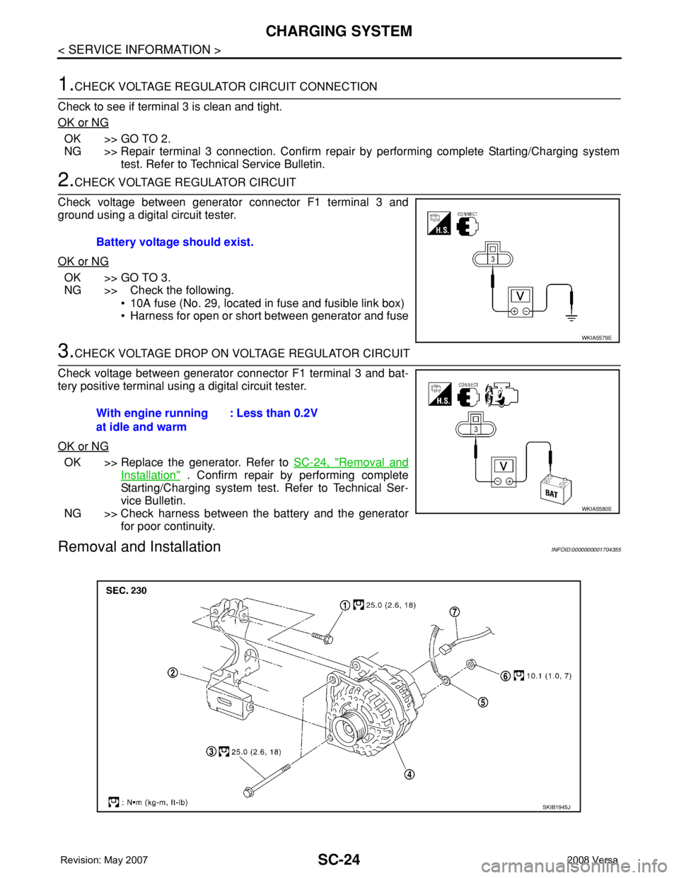
2.CHECK VOLTAGE REGULATOR CIRCUIT
Check voltage between generator connector F1 terminal 3 and
ground using a digital circuit tester.
OK or NG
OK >> GO TO 3.
NG >> Check the following.
• 10A fuse (No. 29, located in fuse and fusible link box)
• Harness for open or short between generator and fuse
3.CHECK VOLTAGE DROP ON VOLTAGE REGULATOR CIRCUIT
Check voltage between generator connector F1 terminal 3 and bat-
tery positive terminal using a digital circuit tester.
OK or NG
OK >> Replace the generator. Refer to SC-24, "Removal and
Installation" . Confirm repair by performing complete
Starting/Charging system test. Refer to Technical Ser-
vice Bulletin.
NG >> Check harness between the battery and the generator
for poor continuity.
Removal and InstallationINFOID:0000000001704355
Battery voltage should exist.
WKIA5579E
With engine running
at idle and warm: Less than 0.2V
WKIA5580E
SKIB1945J
Page 2613 of 2771
SQUEAK AND RATTLE TROUBLE DIAGNOSES
SE-5
< SERVICE INFORMATION >
C
D
E
F
G
H
J
K
L
MA
B
SE
N
O
P
If the noise can be duplicated easily during the test drive, to help identify the source of the noise, try to dupli-
cate the noise with the vehicle stopped by doing one or all of the following:
1) Close a door.
2) Tap or push/pull around the area where the noise appears to be coming from.
3) Rev the engine.
4) Use a floor jack to recreate vehicle “twist”.
5) At idle, apply engine load (electrical load, half-clutch on M/T model, drive position on A/T model).
6) Raise the vehicle on a hoist and hit a tire with a rubber hammer.
• Drive the vehicle and attempt to duplicate the conditions the customer states exist when the noise occurs.
• If it is difficult to duplicate the noise, drive the vehicle slowly on an undulating or rough road to stress the
vehicle body.
CHECK RELATED SERVICE BULLETINS
After verifying the customer concern or symptom, check ASIST for Technical Service Bulletins (TSBs) related
to that concern or symptom.
If a TSB relates to the symptom, follow the procedure to repair the noise.
LOCATE THE NOISE AND IDENTIFY THE ROOT CAUSE
1. Narrow down the noise to a general area.To help pinpoint the source of the noise, use a listening tool
(Chassis Ear: J-39570, Engine Ear: J-39565 and mechanic's stethoscope).
2. Narrow down the noise to a more specific area and identify the cause of the noise by:
• removing the components in the area that you suspect the noise is coming from.
Do not use too much force when removing clips and fasteners, otherwise clips and fasteners can be broken
or lost during the repair, resulting in the creation of new noise.
• tapping or pushing/pulling the component that you suspect is causing the noise.
Do not tap or push/pull the component with excessive force, otherwise the noise will be eliminated only tem-
porarily.
• feeling for a vibration with your hand by touching the component(s) that you suspect is (are) causing the
noise.
• placing a piece of paper between components that you suspect are causing the noise.
• looking for loose components and contact marks.
Refer to SE-6, "
Generic Squeak and Rattle Troubleshooting" .
REPAIR THE CAUSE
• If the cause is a loose component, tighten the component securely.
• If the cause is insufficient clearance between components:
- separate components by repositioning or loosening and retightening the component, if possible.
- insulate components with a suitable insulator such as urethane pads, foam blocks, felt cloth tape or urethane
tape. A NISSAN Squeak and Rattle Kit (J-43980) is available through your authorized NISSAN Parts Depart-
ment.
CAUTION:
Do not use excessive force as many components are constructed of plastic and may be damaged.
Always check with the Parts Department for the latest parts information.
The following materials are contained in the NISSAN Squeak and Rattle Kit (J-43980). Each item can be
ordered separately as needed.
URETHANE PADS [1.5 mm (0.059 in) thick]
Insulates connectors, harness, etc.
76268-9E005: 100×135 mm (3.94×5.31 in)/76884-71L01: 60×85 mm (2.36×3.35 in)/76884-71L02: 15×25
mm (0.59×0.98 in)
INSULATOR (Foam blocks)
Insulates components from contact. Can be used to fill space behind a panel.
73982-9E000: 45 mm (1.77 in) thick, 50×50 mm (1.97×1.97 in)/73982-50Y00: 10 mm (0.39 in) thick,
50×50 mm (1.97×1.97 in)
INSULATOR (Light foam block)
80845-71L00: 30 mm (1.18 in) thick, 30×50 mm (1.18×1.97 in)
FELT CLOTH TAPE
Used to insulate where movement does not occur. Ideal for instrument panel applications.
68370-4B000: 15×25 mm (0.59×0.98 in) pad/68239-13E00: 5 mm (0.20 in) wide tape roll. The following
materials not found in the kit can also be used to repair squeaks and rattles.
UHMW (TEFLON) TAPE
Insulates where slight movement is present. Ideal for instrument panel applications.
Page 2687 of 2771
![NISSAN TIIDA 2008 Service Repair Manual STC-4
< SERVICE INFORMATION >[EPS]
EPS SYSTEM
EPS SYSTEM
System DescriptionINFOID:0000000001703872
EPS CONTROL UNIT
• EPS control unit performs an arithmetical operation on data, such
as steering wh NISSAN TIIDA 2008 Service Repair Manual STC-4
< SERVICE INFORMATION >[EPS]
EPS SYSTEM
EPS SYSTEM
System DescriptionINFOID:0000000001703872
EPS CONTROL UNIT
• EPS control unit performs an arithmetical operation on data, such
as steering wh](/manual-img/5/57399/w960_57399-2686.png)
STC-4
< SERVICE INFORMATION >[EPS]
EPS SYSTEM
EPS SYSTEM
System DescriptionINFOID:0000000001703872
EPS CONTROL UNIT
• EPS control unit performs an arithmetical operation on data, such
as steering wheel turning force (sensor signal) from the torque
sensor, vehicle speed signal, etc. Then it generates an optimum
assist torque to the EPS motor according to the driving condition.
• EPS control unit decreases the output to EPS motor while
extremely using the power steering function (e.g., full steering) for
protecting EPS motor and EPS control unit (Protect overload sta-
tus). While activating protect overload status, the assist torque
gradually decreases, and the steering wheel turning force
becomes heavy. The normal assist torque reactivates by not steer-
ing.
• In case of an error in the electrical system, the fail-safe function
stops output signals to the EPS motor. Then the previous state is changed to the manual steering state.
• Self-diagnosis can be done with CONSULT-III.
EPS MOTOR
EPS motor provides the assist torque by control signal from EPS control unit.
TORQUE SENSOR
Torque sensor detects the steering torque, and transmit the signal to
EPS control unit.
REDUCTION GEAR
Reduction gear increases the assist torque provided from EPS motor with worm gears, and outputs to the col-
umn shaft.
EPS WARNING LAMP
Turns ON when there is a malfunction in EPS system. It indicates that fail-safe mode is engaged and enters a
manual steering state (Control turning force steering wheel becomes heavy).
Also turns ON when ignition switch is turned ON, for purpose of lamp check. Turns OFF after the engine starts
if system is normal.
EPS Warning Lamp Indication
SGIA1647E
SGIA1648E
Condition EPS warning lamp
Lamp checkTurns ON when ignition switch is turned ON.
Turns OFF after engine start.
EPS system malfunctionON
Other than above (system normal) OFF
Page 2695 of 2771
![NISSAN TIIDA 2008 Service Repair Manual STC-12
< SERVICE INFORMATION >[EPS]
TROUBLE DIAGNOSIS
CAUTION:
If “CAN COMM CIRCUIT [U1000]” is displayed with other DTCs, first perform the trouble diagnosis for CAN communication
line.
How to Er NISSAN TIIDA 2008 Service Repair Manual STC-12
< SERVICE INFORMATION >[EPS]
TROUBLE DIAGNOSIS
CAUTION:
If “CAN COMM CIRCUIT [U1000]” is displayed with other DTCs, first perform the trouble diagnosis for CAN communication
line.
How to Er](/manual-img/5/57399/w960_57399-2694.png)
STC-12
< SERVICE INFORMATION >[EPS]
TROUBLE DIAGNOSIS
CAUTION:
If “CAN COMM CIRCUIT [U1000]” is displayed with other DTCs, first perform the trouble diagnosis for CAN communication
line.
How to Erase Self-Diagnostic Results
1. Perform applicable inspection of malfunctioning item and then repair or replace.
2. Turn ignition switch “OFF” to erase memory.
3. Turn ignition switch “ON” and select “SELF-DIAG RESULTS” mode with CONSULT-III.
4. Touch “ERASE” on CONSULT-III screen to erase DTC memory.
CAUTION:
If memory cannot be erased, perform diagnosis.
DATA MONITOR
Display Item List
EPS CONTROL UNIT PART NUMBER
Display a part number of EPS control unit carried by a vehicle.
Item
(CONSULT-III screen terms)Diagnostic item is detected when.... Check item
BATTERY VOLT
[C1601]When the power supply malfunction supplied to EPS control unit is
detected.STC-14, "
DTC C1601
BATTERY VOLT"
TORQUE SENSOR
[C1604]When the torque sensor malfunction assembled in steering column
assembly is detected. STC-15, "DTC C1604
TORQUE SENSOR"
EPS MOTOR
[C1606]When the motor driver malfunction of EPS control unit or EPS motor
malfunction is detected.STC-16, "DTC C1606
EPS MOTOR"
EEPROM
[C1607]When the memory (EEPROM) system malfunction is detected in
EPS control unit.STC-17, "DTC C1607
EEPROM"
CONTROL UNIT
[C1608]When the internal malfunction is detected in EPS control unit.STC-17, "DTC C1608
CONTROL UNIT"
CAN VHCL SPEED
[C1609]When the malfunction is detected in vehicle speed signal received
with CAN communication.STC-18, "DTC C1609
CAN VHCL SPEED"
CAN ENG RPM
[C1610]When the malfunction is detected in engine status signal received
with CAN communication.STC-19, "DTC C1610
CAN ENG RPM"
CAN COMM CIRCUIT
[U1000]When EPS control unit is not transmitting or receiving CAN commu-
nication signal 2 seconds or more.STC-19, "DTC U1000
CAN COMM CIRCUIT"
NO DTC IS DETECTED.
FURTHER TESTING MAY BE RE-
QUIRED.No NG item has been detected. —
Monitor item (Unit) Remarks
MOTOR VOL (V) Power supply voltage for EPS control unit is displayed
TORQUE SENSOR (Nm) Steering wheel turning force detected by torque sensor is displayed
MOTOR SIG (A) Current commanded value to EPS motor is displayed
MOTOR CURRENT (A) Current value consumed by EPS motor is displayed
VEHICLE SPEED (km/h) or (mph) Vehicle speed is displayed from vehicle speed signal with CAN communication
WARNING LAMP (ON/OFF) EPS warning lamp control status is displayed
DERATING STAT (ON/OFF) Protect overload status is displayed
ENGINE STATUS (STOP/RUN) Engine speed is displayed from engine status signal with CAN communication
Page 2696 of 2771
![NISSAN TIIDA 2008 Service Repair Manual TROUBLE DIAGNOSIS
STC-13
< SERVICE INFORMATION >[EPS]
C
D
E
F
H
I
J
K
L
MA
B
STC
N
O
P
Symptom ChartINFOID:0000000001703882
If EPS warning lamp turns ON, perform self-diagnosis. Refer to STC-11, " NISSAN TIIDA 2008 Service Repair Manual TROUBLE DIAGNOSIS
STC-13
< SERVICE INFORMATION >[EPS]
C
D
E
F
H
I
J
K
L
MA
B
STC
N
O
P
Symptom ChartINFOID:0000000001703882
If EPS warning lamp turns ON, perform self-diagnosis. Refer to STC-11, "](/manual-img/5/57399/w960_57399-2695.png)
TROUBLE DIAGNOSIS
STC-13
< SERVICE INFORMATION >[EPS]
C
D
E
F
H
I
J
K
L
MA
B
STC
N
O
P
Symptom ChartINFOID:0000000001703882
If EPS warning lamp turns ON, perform self-diagnosis. Refer to STC-11, "CONSULT-III Function (EPS)" .
Symptom Condition Check item Reference page
EPS warning lamp does not turn ON when ig-
nition switch to “ON”.
(EPS warning lamp check)Ignition switch: ONCAN communication line
STC-21
Combination meter
EPS warning lamp does not turn OFF for sev-
eral seconds after starting the engineEngine runningCAN communication line
STC-21
Power supply and ground for
EPS control unit
Torque sensor
EPS motor
Vehicle speed signal
Engine status signal
Combination meter
Steering wheel turning force is heavy or light,
while driving• While driving
• Steering wheel turningCAN communication line
STC-22
Vehicle speed signal
Engine status signal
EPS motor
Steering wheel turning force
(Mechanical malfunction)
Unbalance steering wheel turning force and
return between right and left, while driving• While driving
• Steering wheel turningWheel alignment
STC-23
Steering wheel turning force
(Mechanical malfunction)
Unbalance steering wheel turning force,
while driving (Torque variation)• While driving
• Steering wheel turningSteering column intermediate
shaft installation condition
STC-24
Steering wheel turning force
(Mechanical malfunction)