2008 NISSAN TIIDA check engine
[x] Cancel search: check enginePage 2458 of 2771
IPDM E/R (INTELLIGENT POWER DISTRIBUTION MODULE ENGINE ROOM)
PG-25
< SERVICE INFORMATION >
C
D
E
F
G
H
I
J
L
MA
B
PG
N
O
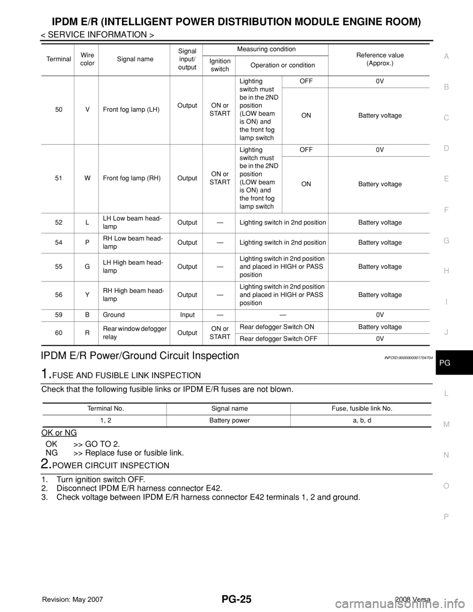
PIPDM E/R Power/Ground Circuit InspectionINFOID:0000000001704704
1.FUSE AND FUSIBLE LINK INSPECTION
Check that the following fusible links or IPDM E/R fuses are not blown.
OK or NG
OK >> GO TO 2.
NG >> Replace fuse or fusible link.
2.POWER CIRCUIT INSPECTION
1. Turn ignition switch OFF.
2. Disconnect IPDM E/R harness connector E42.
3. Check voltage between IPDM E/R harness connector E42 terminals 1, 2 and ground.
50 V Front fog lamp (LH)Output ON or
STARTLighting
switch must
be in the 2ND
position
(LOW beam
is ON) and
the front fog
lamp switchOFF 0V
ON Battery voltage
51 W Front fog lamp (RH) OutputON or
STARTLighting
switch must
be in the 2ND
position
(LOW beam
is ON) and
the front fog
lamp switchOFF 0V
ON Battery voltage
52 LLH Low beam head-
lampOutput — Lighting switch in 2nd position Battery voltage
54 PRH Low beam head-
lampOutput — Lighting switch in 2nd position Battery voltage
55 GLH High beam head-
lampOutput —Lighting switch in 2nd position
and placed in HIGH or PASS
positionBattery voltage
56 YRH High beam head-
lampOutput —Lighting switch in 2nd position
and placed in HIGH or PASS
positionBattery voltage
59 B Ground Input — — 0V
60 RRear window defogger
relayOutputON or
STARTRear defogger Switch ON Battery voltage
Rear defogger Switch OFF 0V Te r m i n a lWire
colorSignal nameSignal
input/
outputMeasuring condition
Reference value
(Approx.) Ignition
switchOperation or condition
Terminal No. Signal name Fuse, fusible link No.
1, 2 Battery power a, b, d
Page 2459 of 2771
PG-26
< SERVICE INFORMATION >
IPDM E/R (INTELLIGENT POWER DISTRIBUTION MODULE ENGINE ROOM)
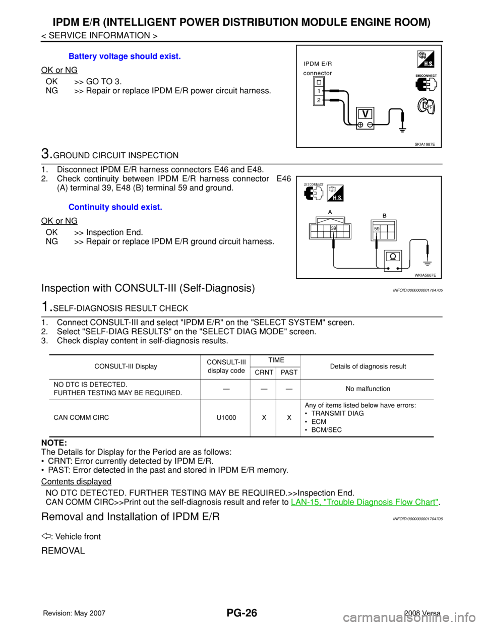
OK or NG
OK >> GO TO 3.
NG >> Repair or replace IPDM E/R power circuit harness.
3.GROUND CIRCUIT INSPECTION
1. Disconnect IPDM E/R harness connectors E46 and E48.
2. Check continuity between IPDM E/R harness connector E46
(A) terminal 39, E48 (B) terminal 59 and ground.
OK or NG
OK >> Inspection End.
NG >> Repair or replace IPDM E/R ground circuit harness.
Inspection with CONSULT-III (Self-Diagnosis)INFOID:0000000001704705
1.SELF-DIAGNOSIS RESULT CHECK
1. Connect CONSULT-III and select "IPDM E/R" on the "SELECT SYSTEM" screen.
2. Select "SELF-DIAG RESULTS" on the "SELECT DIAG MODE" screen.
3. Check display content in self-diagnosis results.
NOTE:
The Details for Display for the Period are as follows:
• CRNT: Error currently detected by IPDM E/R.
• PAST: Error detected in the past and stored in IPDM E/R memory.
Contents displayed
NO DTC DETECTED. FURTHER TESTING MAY BE REQUIRED.>>Inspection End.
CAN COMM CIRC>>Print out the self-diagnosis result and refer to LAN-15, "
Trouble Diagnosis Flow Chart".
Removal and Installation of IPDM E/RINFOID:0000000001704706
: Vehicle front
REMOVAL
Battery voltage should exist.
SKIA1987E
Continuity should exist.
WKIA5667E
CONSULT-III DisplayCONSULT-III
display codeTIME
Details of diagnosis result
CRNT PAST
NO DTC IS DETECTED.
FURTHER TESTING MAY BE REQUIRED.— — — No malfunction
CAN COMM CIRC U1000 X XAny of items listed below have errors:
• TRANSMIT DIAG
•ECM
• BCM/SEC
Page 2512 of 2771
PS-6
< SERVICE INFORMATION >
STEERING WHEEL
STEERING WHEEL
On-Vehicle Inspection and ServiceINFOID:0000000001703859
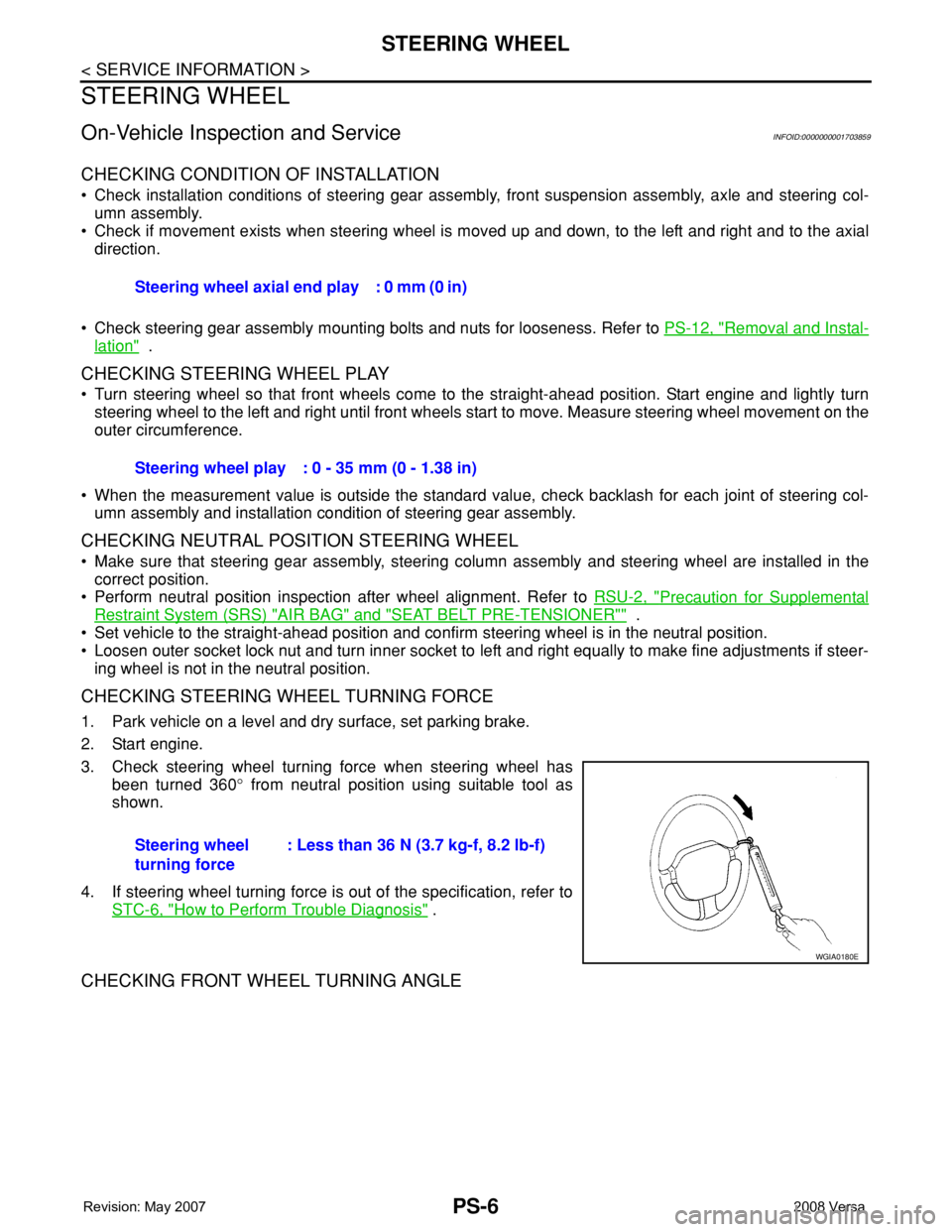
CHECKING CONDITION OF INSTALLATION
• Check installation conditions of steering gear assembly, front suspension assembly, axle and steering col-
umn assembly.
• Check if movement exists when steering wheel is moved up and down, to the left and right and to the axial
direction.
• Check steering gear assembly mounting bolts and nuts for looseness. Refer to PS-12, "
Removal and Instal-
lation" .
CHECKING STEERING WHEEL PLAY
• Turn steering wheel so that front wheels come to the straight-ahead position. Start engine and lightly turn
steering wheel to the left and right until front wheels start to move. Measure steering wheel movement on the
outer circumference.
• When the measurement value is outside the standard value, check backlash for each joint of steering col-
umn assembly and installation condition of steering gear assembly.
CHECKING NEUTRAL POSITION STEERING WHEEL
• Make sure that steering gear assembly, steering column assembly and steering wheel are installed in the
correct position.
• Perform neutral position inspection after wheel alignment. Refer to RSU-2, "
Precaution for Supplemental
Restraint System (SRS) "AIR BAG" and "SEAT BELT PRE-TENSIONER"" .
• Set vehicle to the straight-ahead position and confirm steering wheel is in the neutral position.
• Loosen outer socket lock nut and turn inner socket to left and right equally to make fine adjustments if steer-
ing wheel is not in the neutral position.
CHECKING STEERING WHEEL TURNING FORCE
1. Park vehicle on a level and dry surface, set parking brake.
2. Start engine.
3. Check steering wheel turning force when steering wheel has
been turned 360° from neutral position using suitable tool as
shown.
4. If steering wheel turning force is out of the specification, refer to
STC-6, "
How to Perform Trouble Diagnosis" .
CHECKING FRONT WHEEL TURNING ANGLE
Steering wheel axial end play : 0 mm (0 in)
Steering wheel play : 0 - 35 mm (0 - 1.38 in)
Steering wheel
turning force: Less than 36 N (3.7 kg-f, 8.2 lb-f)
WGIA0180E
Page 2513 of 2771
STEERING WHEEL
PS-7
< SERVICE INFORMATION >
C
D
E
F
H
I
J
K
L
MA
B
PS
N
O
P
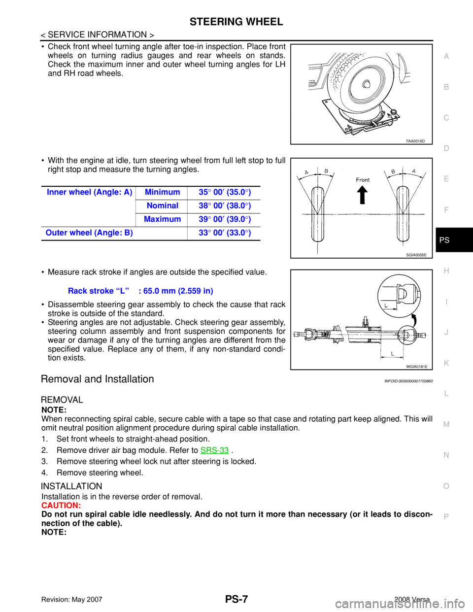
• Check front wheel turning angle after toe-in inspection. Place front
wheels on turning radius gauges and rear wheels on stands.
Check the maximum inner and outer wheel turning angles for LH
and RH road wheels.
• With the engine at idle, turn steering wheel from full left stop to full
right stop and measure the turning angles.
• Measure rack stroke if angles are outside the specified value.
• Disassemble steering gear assembly to check the cause that rack
stroke is outside of the standard.
• Steering angles are not adjustable. Check steering gear assembly,
steering column assembly and front suspension components for
wear or damage if any of the turning angles are different from the
specified value. Replace any of them, if any non-standard condi-
tion exists.
Removal and InstallationINFOID:0000000001703860
REMOVAL
NOTE:
When reconnecting spiral cable, secure cable with a tape so that case and rotating part keep aligned. This will
omit neutral position alignment procedure during spiral cable installation.
1. Set front wheels to straight-ahead position.
2. Remove driver air bag module. Refer to SRS-33
.
3. Remove steering wheel lock nut after steering is locked.
4. Remove steering wheel.
INSTALLATION
Installation is in the reverse order of removal.
CAUTION:
Do not run spiral cable idle needlessly. And do not turn it more than necessary (or it leads to discon-
nection of the cable).
NOTE:
FAA0016D
Inner wheel (Angle: A) Minimum 35° 00′ (35.0°)
Nominal 38° 00′ (38.0°)
Maximum 39° 00′ (39.0°)
Outer wheel (Angle: B) 33° 00′ (33.0°)
SGIA0055E
Rack stroke “L” : 65.0 mm (2.559 in)
WGIA0181E
Page 2535 of 2771
SQUEAK AND RATTLE TROUBLE DIAGNOSES
RF-5
< SYMPTOM DIAGNOSIS >
C
D
E
F
G
H
J
K
L
MA
B
RF
N
O
P
If possible, drive the vehicle with the customer until the noise is duplicated. Note any additional information on
the Diagnostic Worksheet regarding the conditions or location of the noise. This information can be used to
duplicate the same conditions when you confirm the repair.
If the noise can be duplicated easily during the test drive, to help identify the source of the noise, try to dupli-
cate the noise with the vehicle stopped by doing one or all of the following:
1) Close a door.
2) Tap or push/pull around the area where the noise appears to be coming from.
3) Rev the engine.
4) Use a floor jack to recreate vehicle “twist”.
5) At idle, apply engine load (electrical load, half-clutch on M/T model, drive position on A/T model).
6) Raise the vehicle on a hoist and hit a tire with a rubber hammer.
• Drive the vehicle and attempt to duplicate the conditions the customer states exist when the noise occurs.
• If it is difficult to duplicate the noise, drive the vehicle slowly on an undulating or rough road to stress the
vehicle body.
CHECK RELATED SERVICE BULLETINS
After verifying the customer concern or symptom, check ASIST for Technical Service Bulletins (TSBs) related
to that concern or symptom.
If a TSB relates to the symptom, follow the procedure to repair the noise.
LOCATE THE NOISE AND IDENTIFY THE ROOT CAUSE
1. Narrow down the noise to a general area. To help pinpoint the source of the noise, use a listening tool
(Engine Ear or mechanics stethoscope).
2. Narrow down the noise to a more specific area and identify the cause of the noise by:
• removing the components in the area that you suspect the noise is coming from.
Do not use too much force when removing clips and fasteners, otherwise clips and fastener can be broken
or lost during the repair, resulting in the creation of new noise.
• tapping or pushing/pulling the component that you suspect is causing the noise.
Do not tap or push/pull the component with excessive force, otherwise the noise will be eliminated only tem-
porarily.
• feeling for a vibration with your hand by touching the component(s) that you suspect is (are) causing the
noise.
• placing a piece of paper between components that you suspect are causing the noise.
• looking for loose components and contact marks.
Refer to RF-6, "
Generic Squeak and Rattle Troubleshooting".
REPAIR THE CAUSE
• If the cause is a loose component, tighten the component securely.
• If the cause is insufficient clearance between components:
- separate components by repositioning or loosening and retightening the component, if possible.
- insulate components with a suitable insulator such as urethane pads, foam blocks, felt cloth tape or urethane
tape are available through your authorized Nissan Parts Department.
CAUTION:
Do not use excessive force as many components are constructed of plastic and may be damaged.
NOTE:
Always check with the Parts Department for the latest parts information.
Each item can be ordered separately as needed.
URETHANE PADS [1.5 mm (0.059 in) thick]
Insulates connectors, harness, etc.
76268-9E005: 100 × 135 mm (3.94 × 5.31 in)/76884-71L01: 60 × 85 mm (2.36 × 3.35 in)/76884-71L02: 15 ×
25 mm (0.59 × 0.98 in)
INSULATOR (Foam blocks)
Insulates components from contact. Can be used to fill space behind a panel.
73982-9E000: 45 mm (1.77 in) thick, 50 × 50 mm (1.97 × 1.97 in)/73982-50Y00: 10 mm (0.39 in) thick, 50
× 50 mm (1.97 × 1.97 in)
INSULATOR (Light foam block)
80845-71L00: 30 mm (1.18 in) thick, 30 × 50 mm (1.18 × 1.97 in)
FELT CLOTH TAPE
Used to insulate where movement does not occur. Ideal for instrument panel applications.
68370-4B000: 15 × 25 mm (0.59 × 0.98 in) pad/68239-13E00: 5 mm (0.20 in) wide tape roll
Page 2561 of 2771
RSU-2
< SERVICE INFORMATION >
PRECAUTIONS
SERVICE INFORMATION
PRECAUTIONS
Precaution for Supplemental Restraint System (SRS) "AIR BAG" and "SEAT BELT
PRE-TENSIONER"
INFOID:0000000001703732
The Supplemental Restraint System such as “AIR BAG” and “SEAT BELT PRE-TENSIONER”, used along
with a front seat belt, helps to reduce the risk or severity of injury to the driver and front passenger for certain
types of collision. This system includes seat belt switch inputs and dual stage front air bag modules. The SRS
system uses the seat belt switches to determine the front air bag deployment, and may only deploy one front
air bag, depending on the severity of a collision and whether the front occupants are belted or unbelted.
Information necessary to service the system safely is included in the SRS and SB section of this Service Man-
ual.
WARNING:
• To avoid rendering the SRS inoperative, which could increase the risk of personal injury or death in
the event of a collision which would result in air bag inflation, all maintenance must be performed by
an authorized NISSAN/INFINITI dealer.
• Improper maintenance, including incorrect removal and installation of the SRS, can lead to personal
injury caused by unintentional activation of the system. For removal of Spiral Cable and Air Bag
Module, see the SRS section.
• Do not use electrical test equipment on any circuit related to the SRS unless instructed to in this
Service Manual. SRS wiring harnesses can be identified by yellow and/or orange harnesses or har-
ness connectors.
Precaution for Rear SuspensionINFOID:0000000001703733
• When installing the rubber bushings, the final tightening must be done under unladen condition and with the
tires on level ground. Oil will shorten the life of the rubber bushings, so wipe off any spilled oil immediately.
• Unladen condition means the fuel tank, engine coolant and lubricants are at the full specification. The spare
tire, jack, hand tools, and mats are in their designated positions.
• After installing suspension components, check the wheel alignment.
• Caulking nuts are not reusable. Always use new caulking nuts for installation. New caulking nuts are pre-
oiled, do not apply any additional lubrication.
Page 2564 of 2771
REAR SUSPENSION ASSEMBLY
RSU-5
< SERVICE INFORMATION >
C
D
F
G
H
I
J
K
L
MA
B
RSU
N
O
P
REAR SUSPENSION ASSEMBLY
On-Vehicle Inspection and ServiceINFOID:0000000001703736
Make sure the mounting conditions (looseness, backlash) of each component and component conditions
(wear, damage) are within specifications.
SHOCK ABSORBER INSPECTION
Check shock absorber for oil leakage, damage and replace it if necessary.
Wheel AlignmentInspectionINFOID:0000000001703737
DESCRIPTION
Measure wheel alignment under unladen conditions.
NOTE:
“Unladen conditions” means that fuel, engine coolant, and lubricant are full. Spare tire, jack, hand tools and
mats are in designated positions.
PRELIMINARY
Check the following:
1. Tires for improper air pressure and wear.
2. Road wheels for runout. Refer to WT-5
.
3. Wheel bearing axial end play. Refer to RAX-4, "
On-Vehicle Inspection and Service" .
4. Shock absorber operation.
5. Each mounting part of suspension for looseness and deformation.
6. Rear suspension beam for cracks, deformation, and other damage.
7. Vehicle height (posture).
GENERAL INFORMATION AND RECOMMENDATIONS
1. A Four-Wheel Thrust Alignment should be performed.
• This type of alignment is recommended for any NISSAN vehicle.
• The four-wheel “thrust” process helps ensure that the vehicle is properly aligned and the steering wheel
is centered.
• The alignment machine itself should be capable of accepting any NISSAN vehicle.
• The alignment machine should be checked to ensure that it is level.
2. Make sure the alignment machine is properly calibrated.
• Your alignment machine should be regularly calibrated in order to give correct information.
• Check with the manufacturer of your specific alignment machine for their recommended Service/Cali-
bration Schedule.
THE ALIGNMENT PROCESS
IMPORTANT: Use only the alignment specifications listed in this Service Manual. Refer to RSU-12, "Wheel
Alignment (Unladen*)" .
1. When displaying the alignment settings, many alignment machines use “indicators”: (Green/red, plus or
minus, Go/No Go). Do NOT use these indicators.
• The alignment specifications programmed into your alignment machine that operate these indicators
may not be correct.
• This may result in an ERROR.
2. Some newer alignment machines are equipped with an optional “Rolling Compensation” method to “com-
pensate” the sensors (alignment targets or head units). Do NOT use this “Rolling Compensation”
method.
• Use the “Jacking Compensation” method. After installing the alignment targets or head units, raise the
vehicle and rotate the wheels 1/2 turn both ways.
• See Instructions in the alignment machine you are using for more information.
CAMBER INSPECTION
Page 2586 of 2771
SC-4
< SERVICE INFORMATION >
BATTERY
BATTERY
How to Handle BatteryINFOID:0000000001704345
CAUTION:
• If it becomes necessary to start the engine with a booster battery and jumper cables, use a 12-volt
booster battery.
• After connecting battery cables, ensure that they are tightly clamped to battery terminals for good
contact.
• Never add distilled water through the hole used to check specific gravity.
METHODS OF PREVENTING OVER-DISCHARGE
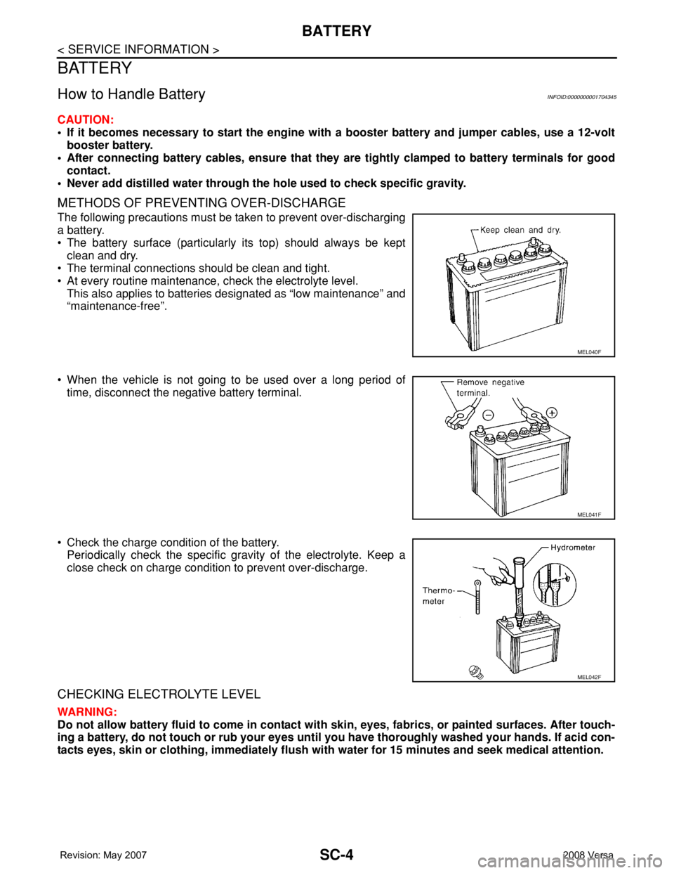
The following precautions must be taken to prevent over-discharging
a battery.
• The battery surface (particularly its top) should always be kept
clean and dry.
• The terminal connections should be clean and tight.
• At every routine maintenance, check the electrolyte level.
This also applies to batteries designated as “low maintenance” and
“maintenance-free”.
• When the vehicle is not going to be used over a long period of
time, disconnect the negative battery terminal.
• Check the charge condition of the battery.
Periodically check the specific gravity of the electrolyte. Keep a
close check on charge condition to prevent over-discharge.
CHECKING ELECTROLYTE LEVEL
WARNING:
Do not allow battery fluid to come in contact with skin, eyes, fabrics, or painted surfaces. After touch-
ing a battery, do not touch or rub your eyes until you have thoroughly washed your hands. If acid con-
tacts eyes, skin or clothing, immediately flush with water for 15 minutes and seek medical attention.
MEL040F
MEL041F
MEL042F