2008 NISSAN TIIDA glove box
[x] Cancel search: glove boxPage 2185 of 2771
LT-48
< SERVICE INFORMATION >
TURN SIGNAL AND HAZARD WARNING LAMPS
TURN SIGNAL AND HAZARD WARNING LAMPS
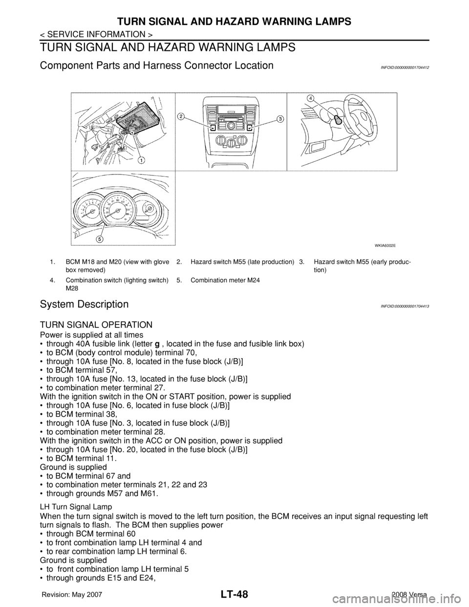
Component Parts and Harness Connector LocationINFOID:0000000001704412
System DescriptionINFOID:0000000001704413
TURN SIGNAL OPERATION
Power is supplied at all times
• through 40A fusible link (letter g , located in the fuse and fusible link box)
• to BCM (body control module) terminal 70,
• through 10A fuse [No. 8, located in the fuse block (J/B)]
• to BCM terminal 57,
• through 10A fuse [No. 13, located in the fuse block (J/B)]
• to combination meter terminal 27.
With the ignition switch in the ON or START position, power is supplied
• through 10A fuse [No. 6, located in fuse block (J/B)]
• to BCM terminal 38,
• through 10A fuse [No. 3, located in fuse block (J/B)]
• to combination meter terminal 28.
With the ignition switch in the ACC or ON position, power is supplied
• through 10A fuse [No. 20, located in the fuse block (J/B)]
• to BCM terminal 11.
Ground is supplied
• to BCM terminal 67 and
• to combination meter terminals 21, 22 and 23
• through grounds M57 and M61.
LH Turn Signal Lamp
When the turn signal switch is moved to the left turn position, the BCM receives an input signal requesting left
turn signals to flash. The BCM then supplies power
• through BCM terminal 60
• to front combination lamp LH terminal 4 and
• to rear combination lamp LH terminal 6.
Ground is supplied
• to front combination lamp LH terminal 5
• through grounds E15 and E24,
1. BCM M18 and M20 (view with glove
box removed)2. Hazard switch M55 (late production) 3. Hazard switch M55 (early produc-
tion)
4. Combination switch (lighting switch)
M285. Combination meter M24
WKIA6002E
Page 2209 of 2771
LT-72
< SERVICE INFORMATION >
PARKING, LICENSE PLATE AND TAIL LAMPS
PARKING, LICENSE PLATE AND TAIL LAMPS
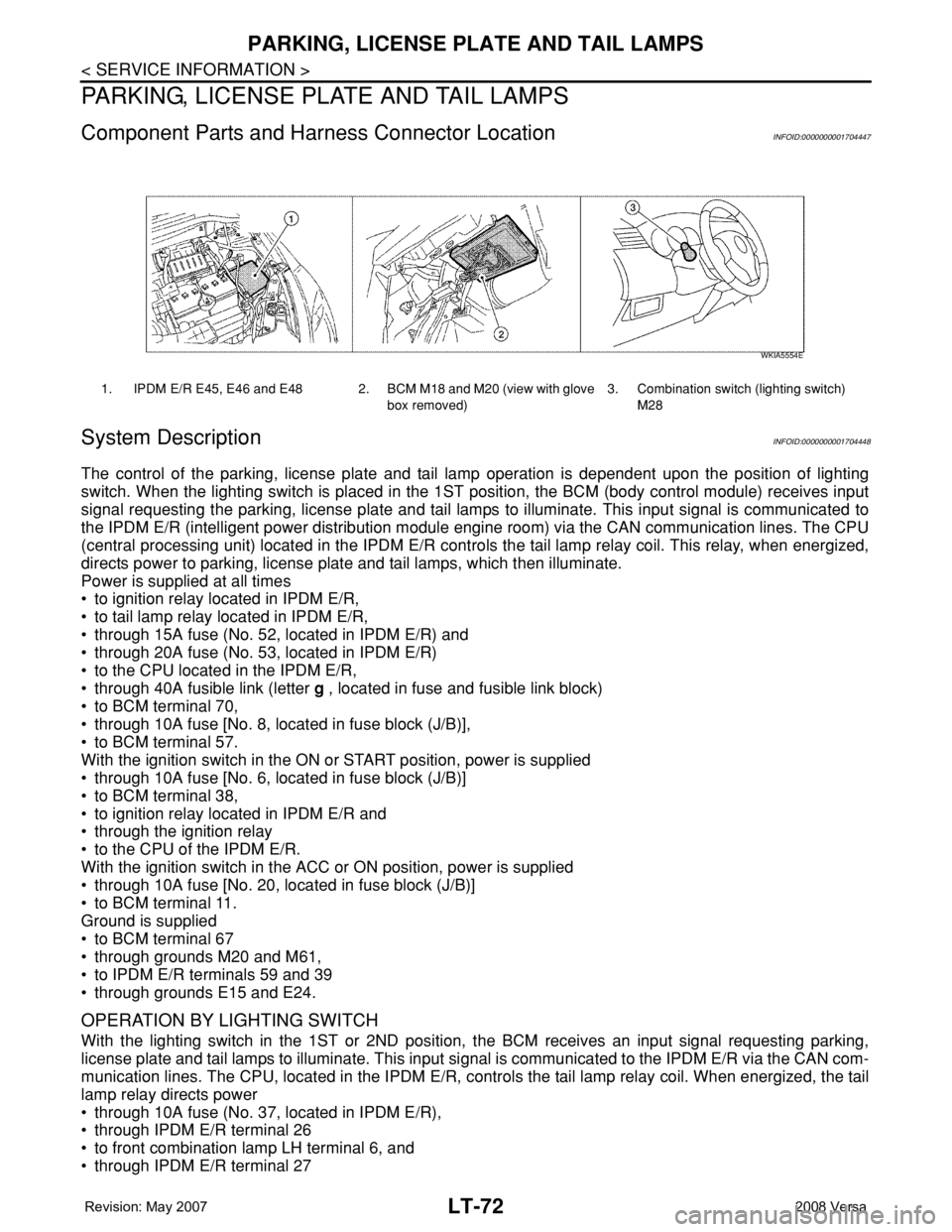
Component Parts and Harness Connector LocationINFOID:0000000001704447
System DescriptionINFOID:0000000001704448
The control of the parking, license plate and tail lamp operation is dependent upon the position of lighting
switch. When the lighting switch is placed in the 1ST position, the BCM (body control module) receives input
signal requesting the parking, license plate and tail lamps to illuminate. This input signal is communicated to
the IPDM E/R (intelligent power distribution module engine room) via the CAN communication lines. The CPU
(central processing unit) located in the IPDM E/R controls the tail lamp relay coil. This relay, when energized,
directs power to parking, license plate and tail lamps, which then illuminate.
Power is supplied at all times
• to ignition relay located in IPDM E/R,
• to tail lamp relay located in IPDM E/R,
• through 15A fuse (No. 52, located in IPDM E/R) and
• through 20A fuse (No. 53, located in IPDM E/R)
• to the CPU located in the IPDM E/R,
• through 40A fusible link (letter g , located in fuse and fusible link block)
• to BCM terminal 70,
• through 10A fuse [No. 8, located in fuse block (J/B)],
• to BCM terminal 57.
With the ignition switch in the ON or START position, power is supplied
• through 10A fuse [No. 6, located in fuse block (J/B)]
• to BCM terminal 38,
• to ignition relay located in IPDM E/R and
• through the ignition relay
• to the CPU of the IPDM E/R.
With the ignition switch in the ACC or ON position, power is supplied
• through 10A fuse [No. 20, located in fuse block (J/B)]
• to BCM terminal 11.
Ground is supplied
• to BCM terminal 67
• through grounds M20 and M61,
• to IPDM E/R terminals 59 and 39
• through grounds E15 and E24.
OPERATION BY LIGHTING SWITCH
With the lighting switch in the 1ST or 2ND position, the BCM receives an input signal requesting parking,
license plate and tail lamps to illuminate. This input signal is communicated to the IPDM E/R via the CAN com-
munication lines. The CPU, located in the IPDM E/R, controls the tail lamp relay coil. When energized, the tail
lamp relay directs power
• through 10A fuse (No. 37, located in IPDM E/R),
• through IPDM E/R terminal 26
• to front combination lamp LH terminal 6, and
• through IPDM E/R terminal 27
1. IPDM E/R E45, E46 and E48 2. BCM M18 and M20 (view with glove
box removed)3. Combination switch (lighting switch)
M28
WKIA5554E
Page 2226 of 2771
INTERIOR ROOM LAMP
LT-89
< SERVICE INFORMATION >
C
D
E
F
G
H
I
J
L
MA
B
LT
N
O
P
INTERIOR ROOM LAMP
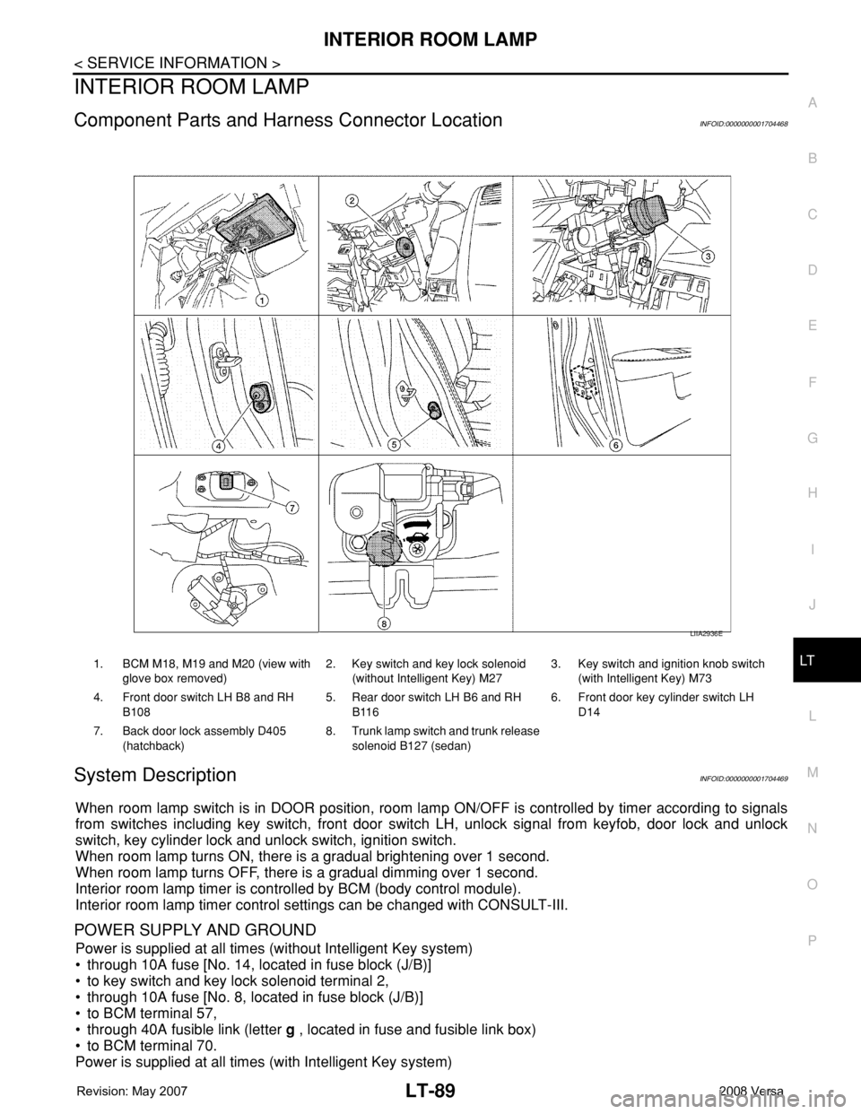
Component Parts and Harness Connector LocationINFOID:0000000001704468
System DescriptionINFOID:0000000001704469
When room lamp switch is in DOOR position, room lamp ON/OFF is controlled by timer according to signals
from switches including key switch, front door switch LH, unlock signal from keyfob, door lock and unlock
switch, key cylinder lock and unlock switch, ignition switch.
When room lamp turns ON, there is a gradual brightening over 1 second.
When room lamp turns OFF, there is a gradual dimming over 1 second.
Interior room lamp timer is controlled by BCM (body control module).
Interior room lamp timer control settings can be changed with CONSULT-III.
POWER SUPPLY AND GROUND
Power is supplied at all times (without Intelligent Key system)
• through 10A fuse [No. 14, located in fuse block (J/B)]
• to key switch and key lock solenoid terminal 2,
• through 10A fuse [No. 8, located in fuse block (J/B)]
• to BCM terminal 57,
• through 40A fusible link (letter g , located in fuse and fusible link box)
• to BCM terminal 70.
Power is supplied at all times (with Intelligent Key system)
1. BCM M18, M19 and M20 (view with
glove box removed)2. Key switch and key lock solenoid
(without Intelligent Key) M273. Key switch and ignition knob switch
(with Intelligent Key) M73
4. Front door switch LH B8 and RH
B1085. Rear door switch LH B6 and RH
B1166. Front door key cylinder switch LH
D14
7. Back door lock assembly D405
(hatchback)8. Trunk lamp switch and trunk release
solenoid B127 (sedan)
LIIA2936E
Page 2242 of 2771

ILLUMINATION
LT-105
< SERVICE INFORMATION >
C
D
E
F
G
H
I
J
L
MA
B
LT
N
O
P
ILLUMINATION
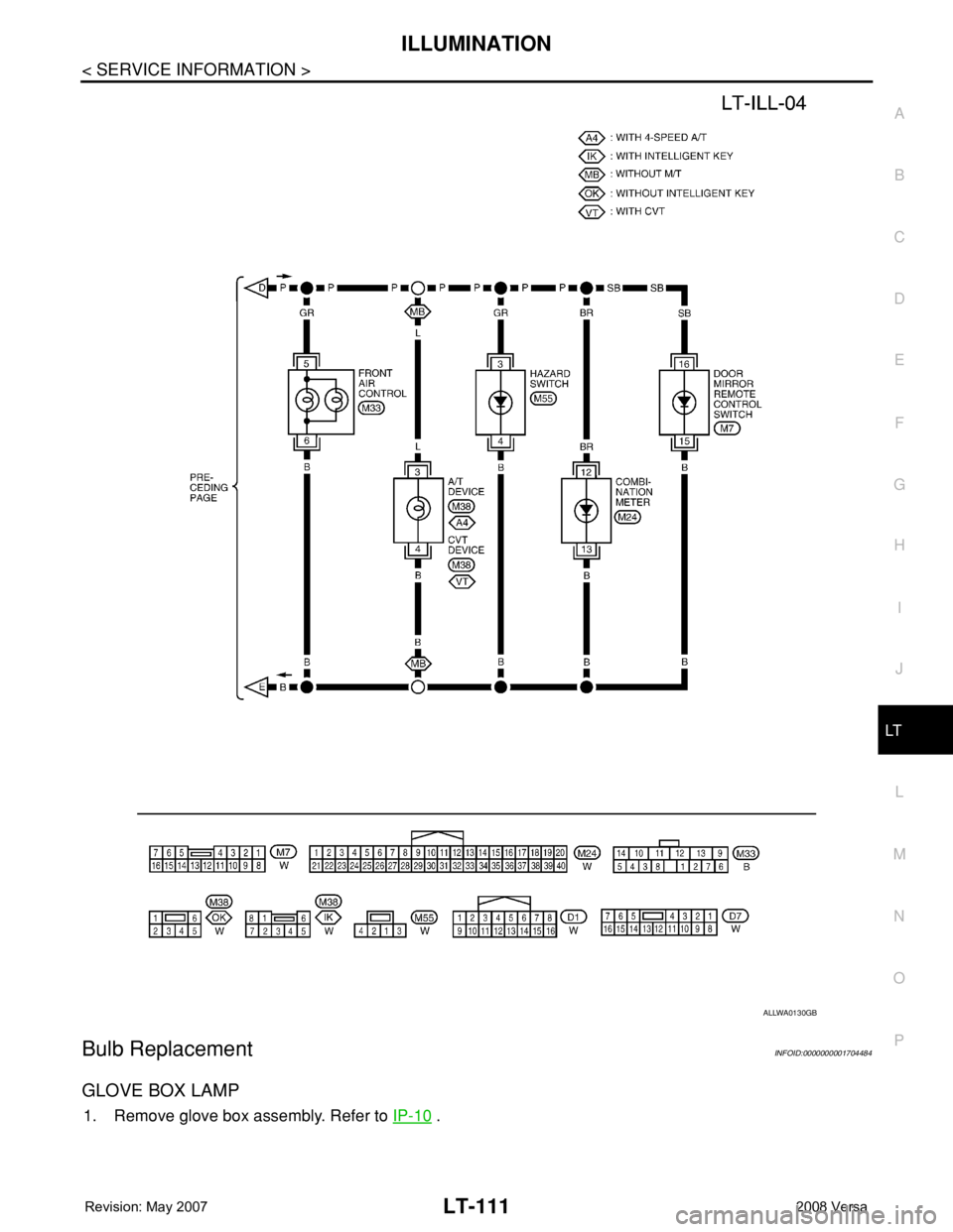
System DescriptionINFOID:0000000001704480
The control of the illumination lamps operation is dependent upon the position of the lighting switch. When the
lighting switch is placed in the 1ST or 2ND position, the BCM (body control module) receives input signal
requesting the illumination lamps to illuminate. This input signal is communicated to IPDM E/R (intelligent
power distribution module engine room) across CAN communication lines. CPU (central processing unit)
located in the IPDM E/R controls the tail lamp relay coil. This relay, when energized, directs power to the illu-
mination lamps, which then illuminate.
Power is supplied at all times
• to ignition relay, located in IPDM E/R,
• to tail lamp relay, located in IPDM E/R,
• through 15A fuse (No. 52, located in IPDM E/R) and
• through 20A fuse (No. 53, located in IPDM E/R)
• to CPU located in IPDM E/R,
• through 40A fusible link (letter g , located in fuse and fusible link box)
• to BCM terminal 70, and
• through 10A fuse [No. 8, located in fuse block (J/B)]
• to BCM terminal 57.
With the ignition switch in the ON or START position, power is supplied
• to ignition relay, located in IPDM E/R, and
• through 10A fuse [No. 6, located in fuse block (J/B)]
• to BCM terminal 38.
With the ignition switch in the ACC or ON position, power is supplied
• through 10A fuse [No. 20, located in fuse block (J/B)]
• to BCM terminal 11.
Ground is supplied
• to BCM terminal 67
• through grounds M57 and M61, and
• to IPDM E/R terminals 39 and 59
• through grounds E15 and E24.
ILLUMINATION OPERATION BY LIGHTING SWITCH
With the lighting switch in the 1ST or 2ND position, BCM receives input signal requesting the illumination
lamps to illuminate. This input signal is communicated to IPDM E/R across CAN communication lines. CPU
located in the IPDM E/R controls the tail lamp relay coil, which, when energized, directs power
• through 10A fuse (No. 37, located in IPDM E/R)
• through IPDM E/R terminal 29
• to microphone terminal 3 (with Bluetooth)
• to illumination control switch terminal 1
• to glove box lamp terminal 1 (with glovebox lamp)
• to audio unit terminal 9
• to front air control terminal 5
• to A/T device terminal 3 (with 4-speed A/T)
• to CVT device terminal 3 (with CVT)
• to hazard switch terminal 3
• to combination meter terminal 12
• to door mirror remote control switch terminal 16, and
Ground is supplied
• to microphone terminal 2 (with Bluetooth)
• to glove box lamp terminal 2 (with glove box lamp), and
• to illumination control switch terminal 3
• through grounds M57 and M61.
The illumination control switch controls illumination intensity by varying the ground to the following
• through illumination control switch terminal 2
• to audio unit terminal 8
• to front air control terminal 6
• to A/T device terminal 4 (with 4-speed A/T)
• to CVT device terminal 3 (with CVT)
• to hazard switch terminal 4
Page 2248 of 2771
ILLUMINATION
LT-111
< SERVICE INFORMATION >
C
D
E
F
G
H
I
J
L
MA
B
LT
N
O
P
Bulb ReplacementINFOID:0000000001704484
GLOVE BOX LAMP
1. Remove glove box assembly. Refer to IP-10 .
ALLWA0130GB
Page 2250 of 2771

BULB SPECIFICATIONS
LT-113
< SERVICE INFORMATION >
C
D
E
F
G
H
I
J
L
MA
B
LT
N
O
P
BULB SPECIFICATIONS
HeadlampINFOID:0000000001704485
Exterior LampINFOID:0000000001704486
Interior Lamp/IlluminationINFOID:0000000001704487
Item Wattage (W)
High/Low (Halogen type)60/55 (HB2)
Item Wattage (W)
Front combination lampTurn signal lamp 21 (amber)
Parking (clearance) lamp 5
Rear combination lampStop/Tail lamp 21/5
Turn signal lamp 21 (amber)
Back-up lamp 21
Front fog lamp35 (H8)
License plate lamp5
High-mounted stop lamp Hatchback LED
Sedan 18
Item Wattage (W)
Glove box lamp1.4
Map lamp8
Room lamp8
Luggage compartment lamp5
Page 2279 of 2771
CHASSIS AND BODY MAINTENANCE
MA-19
< SERVICE INFORMATION >
C
D
E
F
G
H
I
J
K
MA
B
MA
N
O
P
CHASSIS AND BODY MAINTENANCE
Changing In-cabin MicrofilterINFOID:0000000001704739
1. Remove the glove box assembly. Refer to IP-10 .
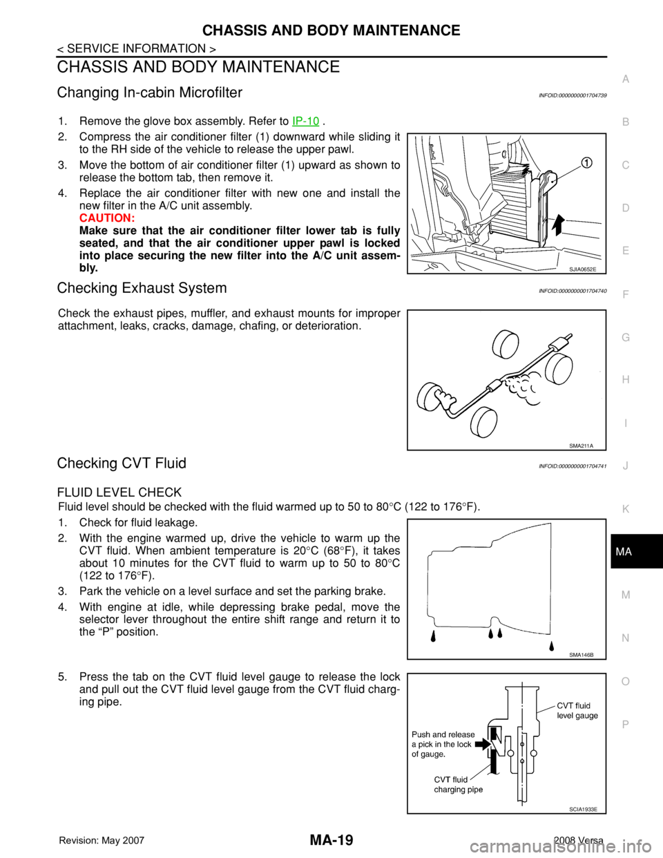
2. Compress the air conditioner filter (1) downward while sliding it
to the RH side of the vehicle to release the upper pawl.
3. Move the bottom of air conditioner filter (1) upward as shown to
release the bottom tab, then remove it.
4. Replace the air conditioner filter with new one and install the
new filter in the A/C unit assembly.
CAUTION:
Make sure that the air conditioner filter lower tab is fully
seated, and that the air conditioner upper pawl is locked
into place securing the new filter into the A/C unit assem-
bly.
Checking Exhaust SystemINFOID:0000000001704740
Check the exhaust pipes, muffler, and exhaust mounts for improper
attachment, leaks, cracks, damage, chafing, or deterioration.
Checking CVT FluidINFOID:0000000001704741
FLUID LEVEL CHECK
Fluid level should be checked with the fluid warmed up to 50 to 80°C (122 to 176°F).
1. Check for fluid leakage.
2. With the engine warmed up, drive the vehicle to warm up the
CVT fluid. When ambient temperature is 20°C (68°F), it takes
about 10 minutes for the CVT fluid to warm up to 50 to 80°C
(122 to 176°F).
3. Park the vehicle on a level surface and set the parking brake.
4. With engine at idle, while depressing brake pedal, move the
selector lever throughout the entire shift range and return it to
the “P” position.
5. Press the tab on the CVT fluid level gauge to release the lock
and pull out the CVT fluid level gauge from the CVT fluid charg-
ing pipe.
SJIA0652E
SMA211A
SMA146B
SCIA1933E
Page 2403 of 2771
MODE DOOR
MTC-65
< SERVICE INFORMATION >
C
D
E
F
G
H
I
K
L
MA
B
MTC
N
O
P
MODE DOOR
Mode Door Cable AdjustmentINFOID:0000000001704317
1. Remove glove box assembly and instrument lower cover (RH). Refer to IP-10.
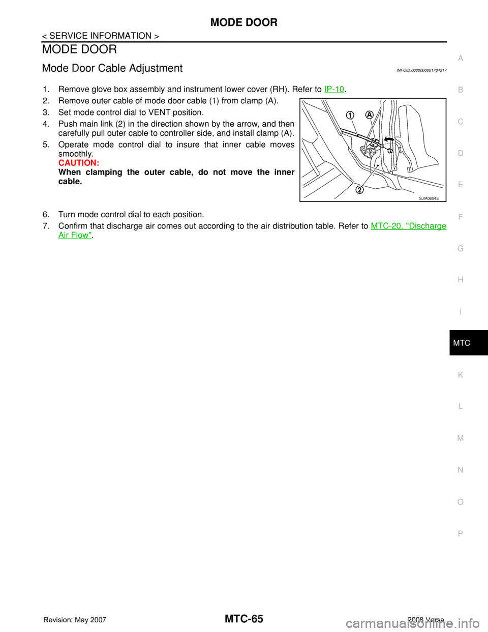
2. Remove outer cable of mode door cable (1) from clamp (A).
3. Set mode control dial to VENT position.
4. Push main link (2) in the direction shown by the arrow, and then
carefully pull outer cable to controller side, and install clamp (A).
5. Operate mode control dial to insure that inner cable moves
smoothly.
CAUTION:
When clamping the outer cable, do not move the inner
cable.
6. Turn mode control dial to each position.
7. Confirm that discharge air comes out according to the air distribution table. Refer to MTC-20, "
Discharge
Air Flow".
SJIA0654E