Page 607 of 2771

TRUNK LID OPENER
BL-173
< SERVICE INFORMATION >
C
D
E
F
G
H
J
K
L
MA
B
BL
N
O
P
TRUNK LID OPENER
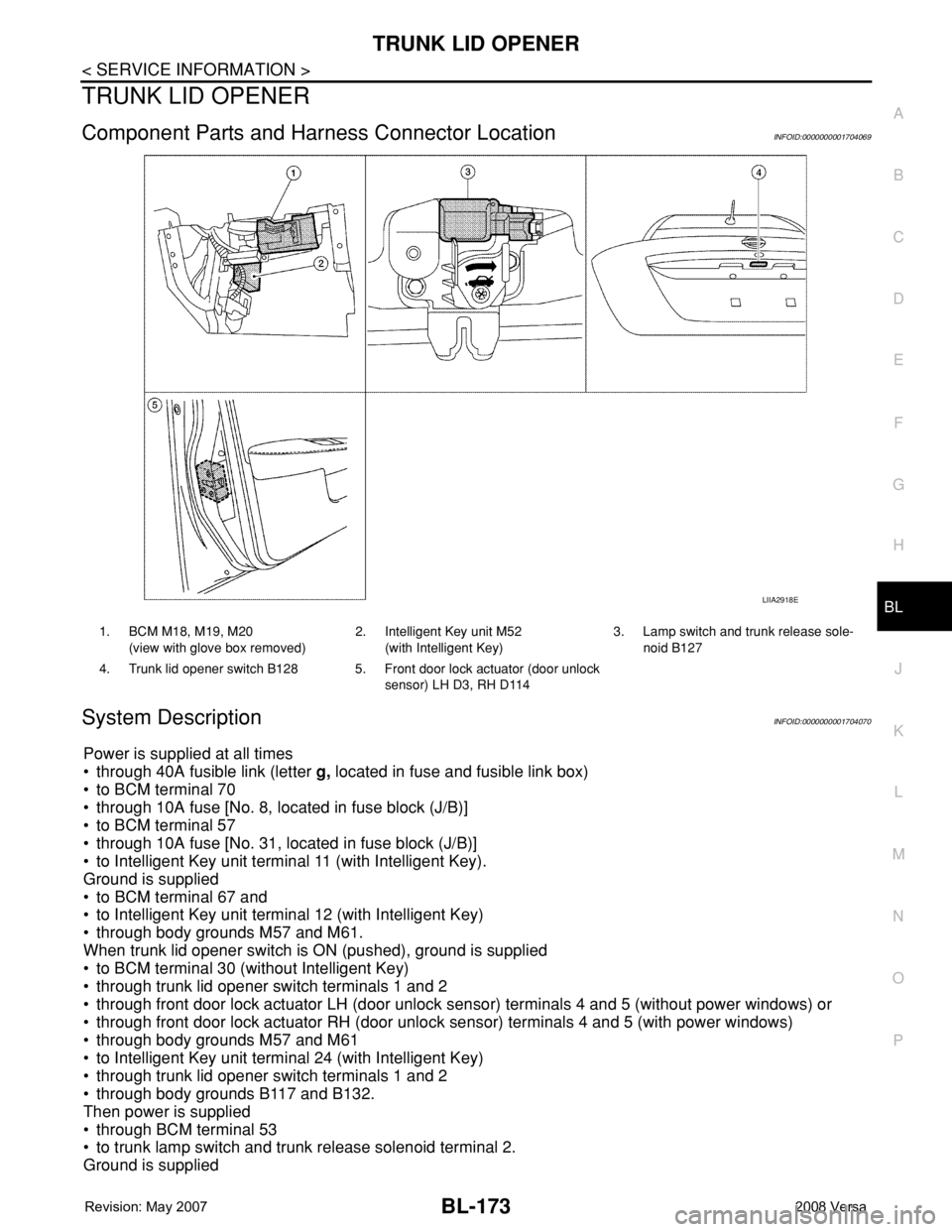
Component Parts and Harness Connector LocationINFOID:0000000001704069
System DescriptionINFOID:0000000001704070
Power is supplied at all times
• through 40A fusible link (letter g, located in fuse and fusible link box)
• to BCM terminal 70
• through 10A fuse [No. 8, located in fuse block (J/B)]
• to BCM terminal 57
• through 10A fuse [No. 31, located in fuse block (J/B)]
• to Intelligent Key unit terminal 11 (with Intelligent Key).
Ground is supplied
• to BCM terminal 67 and
• to Intelligent Key unit terminal 12 (with Intelligent Key)
• through body grounds M57 and M61.
When trunk lid opener switch is ON (pushed), ground is supplied
• to BCM terminal 30 (without Intelligent Key)
• through trunk lid opener switch terminals 1 and 2
• through front door lock actuator LH (door unlock sensor) terminals 4 and 5 (without power windows) or
• through front door lock actuator RH (door unlock sensor) terminals 4 and 5 (with power windows)
• through body grounds M57 and M61
• to Intelligent Key unit terminal 24 (with Intelligent Key)
• through trunk lid opener switch terminals 1 and 2
• through body grounds B117 and B132.
Then power is supplied
• through BCM terminal 53
• to trunk lamp switch and trunk release solenoid terminal 2.
Ground is supplied
LIIA2918E
1. BCM M18, M19, M20
(view with glove box removed)2. Intelligent Key unit M52
(with Intelligent Key)3. Lamp switch and trunk release sole-
noid B127
4. Trunk lid opener switch B128 5. Front door lock actuator (door unlock
sensor) LH D3, RH D114
Page 621 of 2771
VEHICLE SECURITY (THEFT WARNING) SYSTEM
BL-187
< SERVICE INFORMATION >
C
D
E
F
G
H
J
K
L
MA
B
BL
N
O
P
VEHICLE SECURITY (THEFT WARNING) SYSTEM
Component Parts and Harness Connector LocationINFOID:0000000001704083
LIIA2919E
1. Horn relay H-1 2. BCM M18, M19, M20
(view with glove box removed)3. Intelligent Key unit M52
(with Intelligent Key)
4. Combination meter M24 5. Security indicator lamp 6. Front door key cylinder switch LH
D14
7. Front door switch LH B8, RH B108 8. Rear door switch LH B6, RH B116 9. Back door lock assembly (back door
switch) D405 (hatchback view with
back door open)
Page 644 of 2771

BL-210
< SERVICE INFORMATION >
NATS (NISSAN ANTI-THEFT SYSTEM)
NATS (NISSAN ANTI-THEFT SYSTEM)
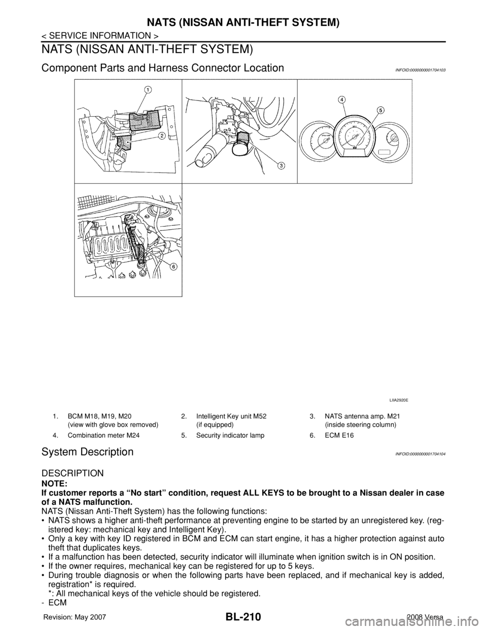
Component Parts and Harness Connector LocationINFOID:0000000001704103
System DescriptionINFOID:0000000001704104
DESCRIPTION
NOTE:
If customer reports a “No start” condition, request ALL KEYS to be brought to a Nissan dealer in case
of a NATS malfunction.
NATS (Nissan Anti-Theft System) has the following functions:
• NATS shows a higher anti-theft performance at preventing engine to be started by an unregistered key. (reg-
istered key: mechanical key and Intelligent Key).
• Only a key with key ID registered in BCM and ECM can start engine, it has a higher protection against auto
theft that duplicates keys.
• If a malfunction has been detected, security indicator will illuminate when ignition switch is in ON position.
• If the owner requires, mechanical key can be registered for up to 5 keys.
• During trouble diagnosis or when the following parts have been replaced, and if mechanical key is added,
registration* is required.
*: All mechanical keys of the vehicle should be registered.
-ECM
LIIA2920E
1. BCM M18, M19, M20
(view with glove box removed)2. Intelligent Key unit M52
(if equipped)3. NATS antenna amp. M21
(inside steering column)
4. Combination meter M24 5. Security indicator lamp 6. ECM E16
Page 1062 of 2771
WARNING CHIME
DI-41
< SERVICE INFORMATION >
C
D
E
F
G
H
I
J
L
MA
B
DI
N
O
P
WARNING CHIME
Component Parts and Harness Connector LocationINFOID:0000000001704521
System DescriptionINFOID:0000000001704522
• Buzzer for warning chime system is installed in the combination meter.
• The buzzer sounds when combination meter receives buzzer output signal with CAN communication line.
POWER SUPPLY AND GROUND CIRCUIT
Power is supplied at all times
• through 40A fusible link (letter g, located in the fuse and fusible link box)
• to BCM terminal 70,
1. Combination meter M24 2. BCM M18, M19, M20 (view with
glove box removed)3. Intelligent Key unit M52 (with Intelli-
gent Key)
4. Key switch and key lock solenoid
M27 (without Intelligent Key)5. Key switch and ignition knob switch
M73 (with Intelligent Key)6. Combination switch (lighting switch)
M28
7. Front door switch LH B8 8. Parking brake switch M17
AWMIA0117ZZ
Page 1913 of 2771

GW-12
< SERVICE INFORMATION >
WINDSHIELD GLASS
WARNING:
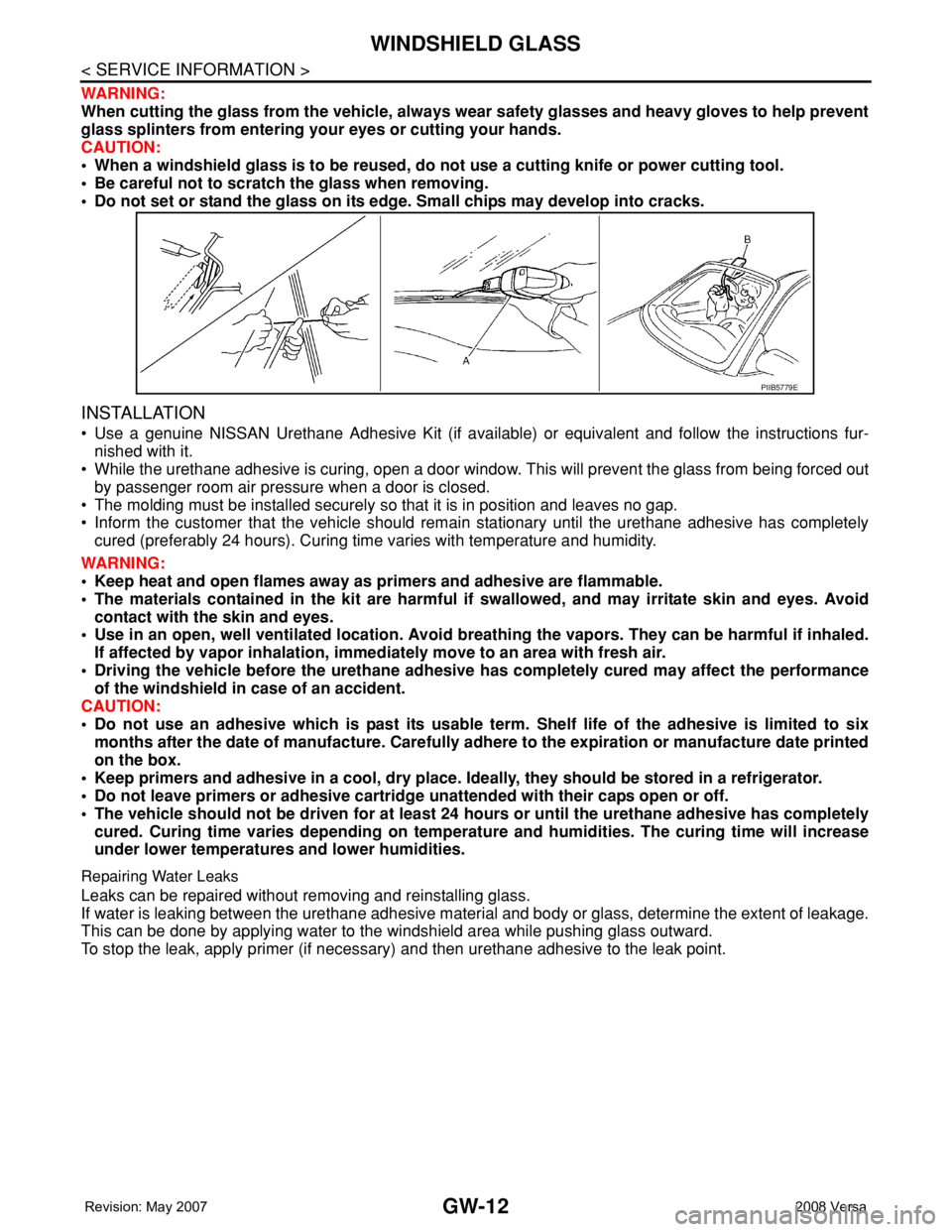
When cutting the glass from the vehicle, always wear safety glasses and heavy gloves to help prevent
glass splinters from entering your eyes or cutting your hands.
CAUTION:
• When a windshield glass is to be reused, do not use a cutting knife or power cutting tool.
• Be careful not to scratch the glass when removing.
• Do not set or stand the glass on its edge. Small chips may develop into cracks.
INSTALLATION
• Use a genuine NISSAN Urethane Adhesive Kit (if available) or equivalent and follow the instructions fur-
nished with it.
• While the urethane adhesive is curing, open a door window. This will prevent the glass from being forced out
by passenger room air pressure when a door is closed.
• The molding must be installed securely so that it is in position and leaves no gap.
• Inform the customer that the vehicle should remain stationary until the urethane adhesive has completely
cured (preferably 24 hours). Curing time varies with temperature and humidity.
WARNING:
• Keep heat and open flames away as primers and adhesive are flammable.
• The materials contained in the kit are harmful if swallowed, and may irritate skin and eyes. Avoid
contact with the skin and eyes.
• Use in an open, well ventilated location. Avoid breathing the vapors. They can be harmful if inhaled.
If affected by vapor inhalation, immediately move to an area with fresh air.
• Driving the vehicle before the urethane adhesive has completely cured may affect the performance
of the windshield in case of an accident.
CAUTION:
• Do not use an adhesive which is past its usable term. Shelf life of the adhesive is limited to six
months after the date of manufacture. Carefully adhere to the expiration or manufacture date printed
on the box.
• Keep primers and adhesive in a cool, dry place. Ideally, they should be stored in a refrigerator.
• Do not leave primers or adhesive cartridge unattended with their caps open or off.
• The vehicle should not be driven for at least 24 hours or until the urethane adhesive has completely
cured. Curing time varies depending on temperature and humidities. The curing time will increase
under lower temperatures and lower humidities.
Repairing Water Leaks
Leaks can be repaired without removing and reinstalling glass.
If water is leaking between the urethane adhesive material and body or glass, determine the extent of leakage.
This can be done by applying water to the windshield area while pushing glass outward.
To stop the leak, apply primer (if necessary) and then urethane adhesive to the leak point.
PIIB5779E
Page 1919 of 2771
GW-18
< SERVICE INFORMATION >
POWER WINDOW SYSTEM
POWER WINDOW SYSTEM
Component Parts and Harness Connector LocationINFOID:0000000001704138
System DescriptionINFOID:0000000001704139
Power is supplied at all times
• through 40A fusible link (letter g , located in the fuse and fusible link box)
• to BCM terminal 70.
With ignition switch in ON or START position, power is supplied
• through 10A fuse [No. 6, located in the fuse block (J/B)]
• to BCM terminal 38
1. Main power window and door lock/
unlock switch D7, D82. Power window and door lock/unlock
switch RH D1053. Rear power window switch LH D203,
RH D303
4. BCM M18, M19, M20 (view with
glove box removed)5. Front power window motor LH D9,
RH D1046. Rear power window motor LH D204,
RH D304
7. Front door switch LH B8, RH B108
LIIA2529E
Page 1950 of 2771
REAR WINDOW DEFOGGER
GW-49
< SERVICE INFORMATION >
C
D
E
F
G
H
J
K
L
MA
B
GW
N
O
P
REAR WINDOW DEFOGGER
Component Parts and Harness Connector LocationINFOID:0000000001704166
System DescriptionINFOID:0000000001704167
The rear window defogger system is controlled by BCM (body control module) and IPDM E/R (intelligent
power distribution module engine room).
The rear window defogger only operates for approximately 15 minutes.
1. BCM M18, M20 (view with glove box
removed)2. Front air control M33 3. A. Rear window defogger ground
connector D413 (Hatchback)
B. Rear window defogger connector
D412 (Hatchback)
C. Condenser-1 D409, D411 (Hatch-
back)
4. A. Rear window defogger connector
B140 (Sedan)
B. Rear window defogger ground
connector B141 (Sedan)
C. Condenser-1 B130, B131 (Se-
dan)5. IPDM E/R E46, E48 6. Door mirror LH D4, RH D107 (with
heated mirrors)
7. Heated mirror relay M48 (with heat-
ed mirrors)
LIIA2929E
Page 1977 of 2771

INSTRUMENT PANEL ASSEMBLY
IP-11
< ON-VEHICLE REPAIR >
C
D
E
F
G
H
J
K
L
MA
B
IP
N
O
P
Removal and InstallationINFOID:0000000001704252
WORK STEPS
When removing instrument panel & pad, cluster lid A, cluster lid C, passenger air bag module assembly and
center console assembly, follow steps in the order shown.
CAUTION:
• Disconnect both battery cables.
• Never tamper with or force air bag lid open, as this may adversely affect air bag performance.
• Be careful not to scratch pad and other parts.
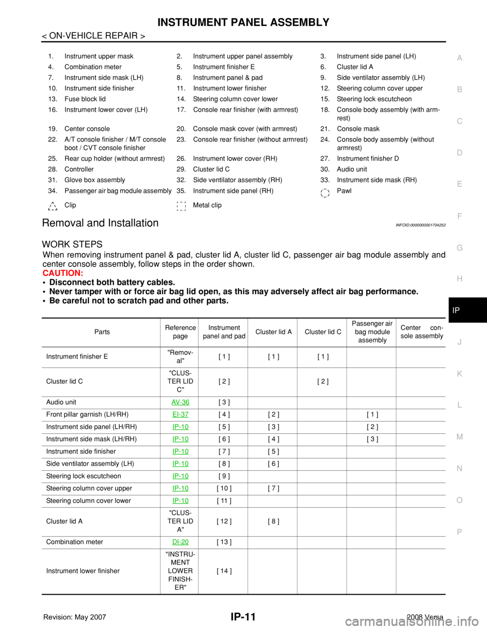
1. Instrument upper mask 2. Instrument upper panel assembly 3. Instrument side panel (LH)
4. Combination meter 5. Instrument finisher E 6. Cluster lid A
7. Instrument side mask (LH) 8. Instrument panel & pad 9. Side ventilator assembly (LH)
10. Instrument side finisher 11. Instrument lower finisher 12. Steering column cover upper
13. Fuse block lid 14. Steering column cover lower 15. Steering lock escutcheon
16. Instrument lower cover (LH) 17. Console rear finisher (with armrest) 18. Console body assembly (with arm-
rest)
19. Center console 20. Console mask cover (with armrest) 21. Console mask
22. A/T console finisher / M/T console
boot / CVT console finisher23. Console rear finisher (without armrest) 24. Console body assembly (without
armrest)
25. Rear cup holder (without armrest) 26. Instrument lower cover (RH) 27. Instrument finisher D
28. Controller 29. Cluster lid C 30. Audio unit
31. Glove box assembly 32. Side ventilator assembly (RH) 33. Instrument side mask (RH)
34. Passenger air bag module assembly 35. Instrument side panel (RH) Pawl
Clip Metal clip
PartsReference
pageInstrument
panel and padCluster lid A Cluster lid C Passenger air
bag module
assemblyCenter con-
sole assembly
Instrument finisher E"Remov-
al"[ 1 ] [ 1 ] [ 1 ]
Cluster lid C"CLUS-
TER LID
C"[ 2 ] [ 2 ]
Audio unitAV- 3 6
[ 3 ]
Front pillar garnish (LH/RH)EI-37
[ 4 ] [ 2 ] [ 1 ]
Instrument side panel (LH/RH)IP-10
[ 5 ] [ 3 ] [ 2 ]
Instrument side mask (LH/RH)IP-10
[ 6 ] [ 4 ] [ 3 ]
Instrument side finisherIP-10
[ 7 ] [ 5 ]
Side ventilator assembly (LH)IP-10
[ 8 ] [ 6 ]
Steering lock escutcheonIP-10
[ 9 ]
Steering column cover upperIP-10
[ 10 ] [ 7 ]
Steering column cover lowerIP-10
[ 11 ]
Cluster lid A"CLUS-
TER LID
A"[ 12 ] [ 8 ]
Combination meterDI-20
[ 13 ]
Instrument lower finisher"INSTRU-
MENT
LOWER
FINISH-
ER"[ 14 ]