2008 NISSAN TIIDA diagnostic
[x] Cancel search: diagnosticPage 2148 of 2771
HEADLAMP (FOR USA)
LT-11
< SERVICE INFORMATION >
C
D
E
F
G
H
I
J
L
MA
B
LT
N
O
P
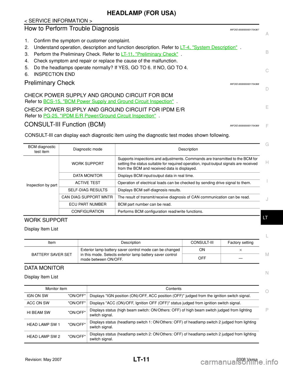
How to Perform Trouble DiagnosisINFOID:0000000001704367
1. Confirm the symptom or customer complaint.
2. Understand operation, description and function description. Refer to LT- 4 , "
System Description" .
3. Perform the Preliminary Check. Refer to LT- 11 , "
Preliminary Check" .
4. Check symptom and repair or replace the cause of the malfunction.
5. Do the headlamps operate normally? If YES, GO TO 6. If NO, GO TO 4.
6. INSPECTION END
Preliminary CheckINFOID:0000000001704368
CHECK POWER SUPPLY AND GROUND CIRCUIT FOR BCM
Refer to BCS-15, "BCM Power Supply and Ground Circuit Inspection" .
CHECK POWER SUPPLY AND GROUND CIRCUIT FOR IPDM E/R
Refer to PG-25, "IPDM E/R Power/Ground Circuit Inspection" .
CONSULT-III Function (BCM)INFOID:0000000001704369
CONSULT-III can display each diagnostic item using the diagnostic test modes shown following.
WORK SUPPORT
Display Item List
DATA MONITOR
Display Item List
BCM diagnostic
test itemDiagnostic mode Description
Inspection by partWORK SUPPORTSupports inspections and adjustments. Commands are transmitted to the BCM for
setting the status suitable for required operation, input/output signals are received
from the BCM and received data is displayed.
DATA MONITOR Displays BCM input/output data in real time.
ACTIVE TEST Operation of electrical loads can be checked by sending drive signal to them.
SELF-DIAG RESULTS Displays BCM self-diagnosis results.
CAN DIAG SUPPORT MNTR The result of transmit/receive diagnosis of CAN communication can be read.
ECU PART NUMBER BCM part number can be read.
CONFIGURATION Performs BCM configuration read/write functions.
Item Description CONSULT-III Factory setting
BATTERY SAVER SETExterior lamp battery saver control mode can be changed
in this mode. Selects exterior lamp battery saver control
mode between ON/OFF.ON×
OFF —
Monitor item Contents
IGN ON SW "ON/OFF" Displays "IGN position (ON)/OFF, ACC position (OFF)" judged from the ignition switch signal.
ACC ON SW "ON/OFF" Displays "ACC (ON)/OFF, Ignition OFF (OFF)" status judged from ignition switch signal.
HI BEAM SW "ON/OFF"Displays status (high beam switch: ON/Others: OFF) of high beam switch judged from lighting
switch signal.
HEAD LAMP SW 1 "ON/OFF"Displays status (headlamp switch 1: ON/Others: OFF) of headlamp switch 2 judged from lighting
switch signal.
HEAD LAMP SW 2 "ON/OFF"Displays status (headlamp switch 2: ON/Others: OFF) of headlamp switch 2 judged from lighting
switch signal.
Page 2149 of 2771

LT-12
< SERVICE INFORMATION >
HEADLAMP (FOR USA)
Note 1: Vehicles without daytime light system may display this item, but cannot monitor it.
ACTIVE TEST
Display Item List
SELF-DIAGNOSTIC RESULTS
Display Item List
CONSULT-III Function (IPDM E/R)INFOID:0000000001704370
CONSULT-III can display each diagnostic item using the diagnostic test modes shown following.
DATA MONITOR
All Items, Main Items, Select Item Menu
LIGHT SW 1ST "ON/OFF"Displays status (lighting switch 1st position: ON/Others: OFF) of lighting switch judged from lighting
switch signal.
PASSING SW "ON/OFF"Displays status (flash-to-pass switch: ON/Others: OFF) of flash-to-pass switch judged from lighting
switch signal.
FR FOG SW "ON/OFF"Displays status (front fog lamp switch: ON/Others: OFF) of front fog lamp switch judged from light-
ing switch signal.
DOOR SW - DR "ON/OFF"Displays status of the front door LH as judged from the front door switch LH signal. (Door is open:
ON/Door is closed: OFF)
DOOR SW - AS "ON/OFF"Displays status of the front door RH as judged from the front door switch RH signal. (Door is open:
ON/Door is closed: OFF)
DOOR SW - RR "ON/OFF"Displays status of the rear door as judged from the rear door switch (RH) signal. (Door is open:
ON/Door is closed: OFF)
DOOR SW - RL "ON/OFF"Displays status of the rear door as judged from the rear door switch (LH) signal. (Door is open: ON/
Door is closed: OFF)
BACK DOOR SW "ON/OFF"Displays status of the back door as judged from the back door switch signal. (Door is open: ON/
Door is closed: OFF)
TURN SIGNAL R "ON/OFF" Displays status (Turn right: ON/Others: OFF) as judged from lighting switch signal.
TURN SIGNAL L "ON/OFF" Displays status (Turn left: ON/Others: OFF) as judged from lighting switch signal.
ENGINE RUN
Note 1"ON/OFF" Displays status (Engine running: ON/Others: OFF) as judged from engine status signal.
PKB SW
Note 1"ON/OFF"Displays status (Parking brake switch: ON/Others: OFF) as judged from parking brake switch sig-
nal. Monitor item Contents
Test item Description
TAIL LAMP Allows tail lamp relay to operate by switching ON-OFF.
HEAD LAMP Allows headlamp relay (HI, LO) to operate by switching ON-OFF.
FR FOG LAMP Allows fog lamp relay to operate by switching ON-OFF.
Monitored item CONSULT-llI display Description
CAN communication CAN communication [U1000] Malfunction is detected in CAN communication.
CAN communication system CAN communication system 1 to 6 [U1000] Malfunction is detected in CAN system.
IPDM E/R diagnostic Mode Description
SELF-DIAG RESULTS Displays IPDM E/R self-diagnosis results.
DATA MONITOR Displays IPDM E/R input/output data in real time.
CAN DIAG SUPPORT MNTR The result of transmit/receive diagnosis of CAN communication can be read.
ACTIVE TEST Operation of electrical loads can be checked by sending drive signal to them.
Page 2360 of 2771
MTC-22
< SERVICE INFORMATION >
TROUBLE DIAGNOSIS
TROUBLE DIAGNOSIS
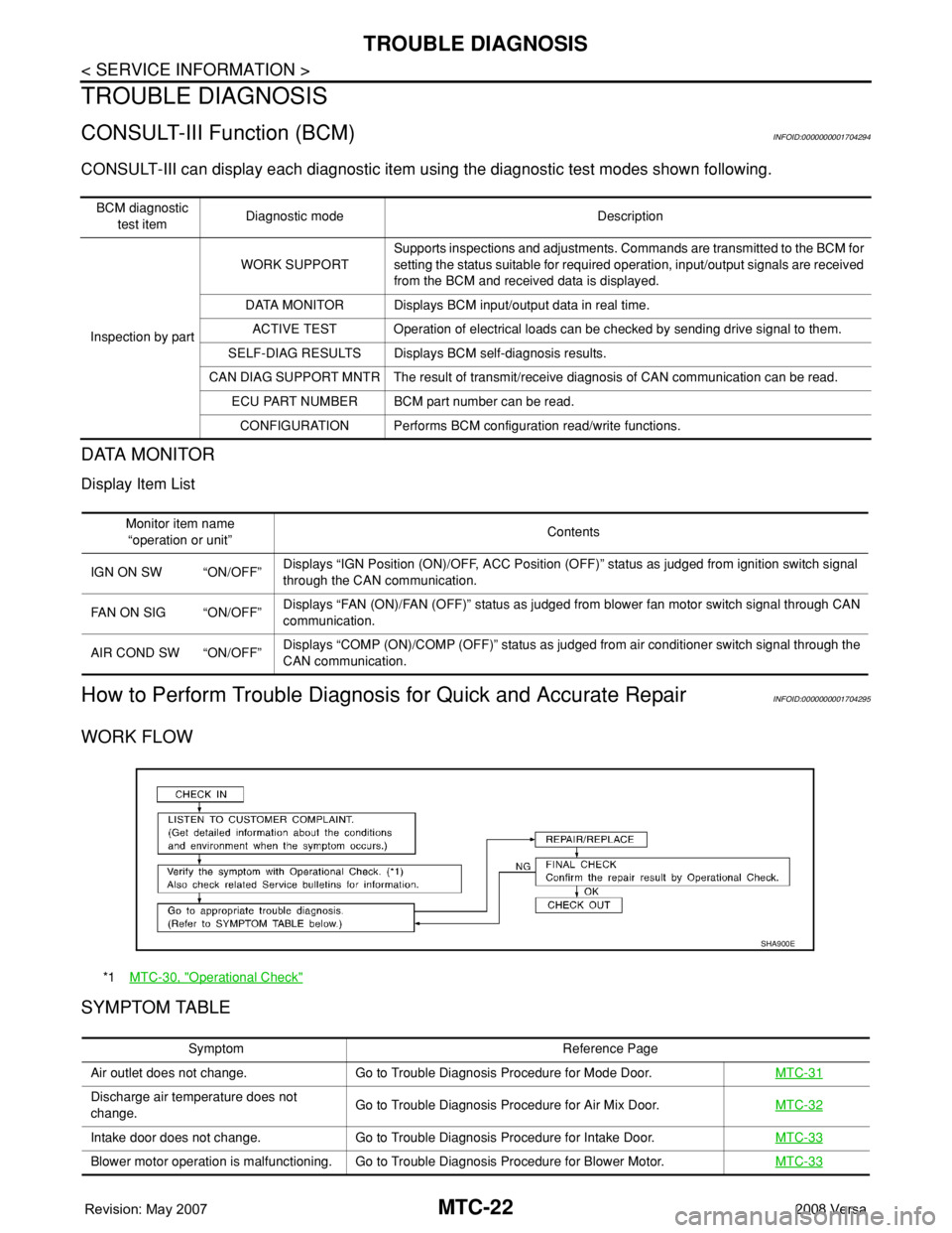
CONSULT-III Function (BCM)INFOID:0000000001704294
CONSULT-III can display each diagnostic item using the diagnostic test modes shown following.
DATA MONITOR
Display Item List
How to Perform Trouble Diagnosis for Quick and Accurate RepairINFOID:0000000001704295
WORK FLOW
SYMPTOM TABLE
BCM diagnostic
test itemDiagnostic mode Description
Inspection by partWORK SUPPORTSupports inspections and adjustments. Commands are transmitted to the BCM for
setting the status suitable for required operation, input/output signals are received
from the BCM and received data is displayed.
DATA MONITOR Displays BCM input/output data in real time.
ACTIVE TEST Operation of electrical loads can be checked by sending drive signal to them.
SELF-DIAG RESULTS Displays BCM self-diagnosis results.
CAN DIAG SUPPORT MNTR The result of transmit/receive diagnosis of CAN communication can be read.
ECU PART NUMBER BCM part number can be read.
CONFIGURATION Performs BCM configuration read/write functions.
Monitor item name
“operation or unit”Contents
IGN ON SW “ON/OFF”Displays “IGN Position (ON)/OFF, ACC Position (OFF)” status as judged from ignition switch signal
through the CAN communication.
FAN ON SIG “ON/OFF”Displays “FAN (ON)/FAN (OFF)” status as judged from blower fan motor switch signal through CAN
communication.
AIR COND SW “ON/OFF”Displays “COMP (ON)/COMP (OFF)” status as judged from air conditioner switch signal through the
CAN communication.
*1MTC-30, "Operational Check"
SHA900E
Symptom Reference Page
Air outlet does not change. Go to Trouble Diagnosis Procedure for Mode Door.MTC-31
Discharge air temperature does not
change.Go to Trouble Diagnosis Procedure for Air Mix Door.MTC-32
Intake door does not change. Go to Trouble Diagnosis Procedure for Intake Door.MTC-33
Blower motor operation is malfunctioning. Go to Trouble Diagnosis Procedure for Blower Motor.MTC-33
Page 2372 of 2771
MTC-34
< SERVICE INFORMATION >
TROUBLE DIAGNOSIS
NO >> GO TO 3.
2.PERFORM COMPLETE OPERATIONAL CHECK
Perform a complete operational check and check for any symptoms. Refer to MTC-30, "
Operational Check".
Can a symptom be duplicated?
YES >> Refer to MTC-22, "How to Perform Trouble Diagnosis for Quick and Accurate Repair".
NO >> System OK.
3.CHECK FOR SERVICE BULLETINS
Check for any service bulletins.
>> GO TO 4.
4.CHECK FRONT BLOWER MOTOR CIRCUIT
Check front blower motor circuit. Refer to "DIAGNOSTIC PROCEDURE FOR FRONT BLOWER MOTOR" .
OK or NG?
OK >> If the symptom still exists, perform a complete operational check. Refer to MTC-30, "Operational
Check". If other symptoms exist, refer to MTC-22, "How to Perform Trouble Diagnosis for Quick
and Accurate Repair".
NG >> Repair as necessary.
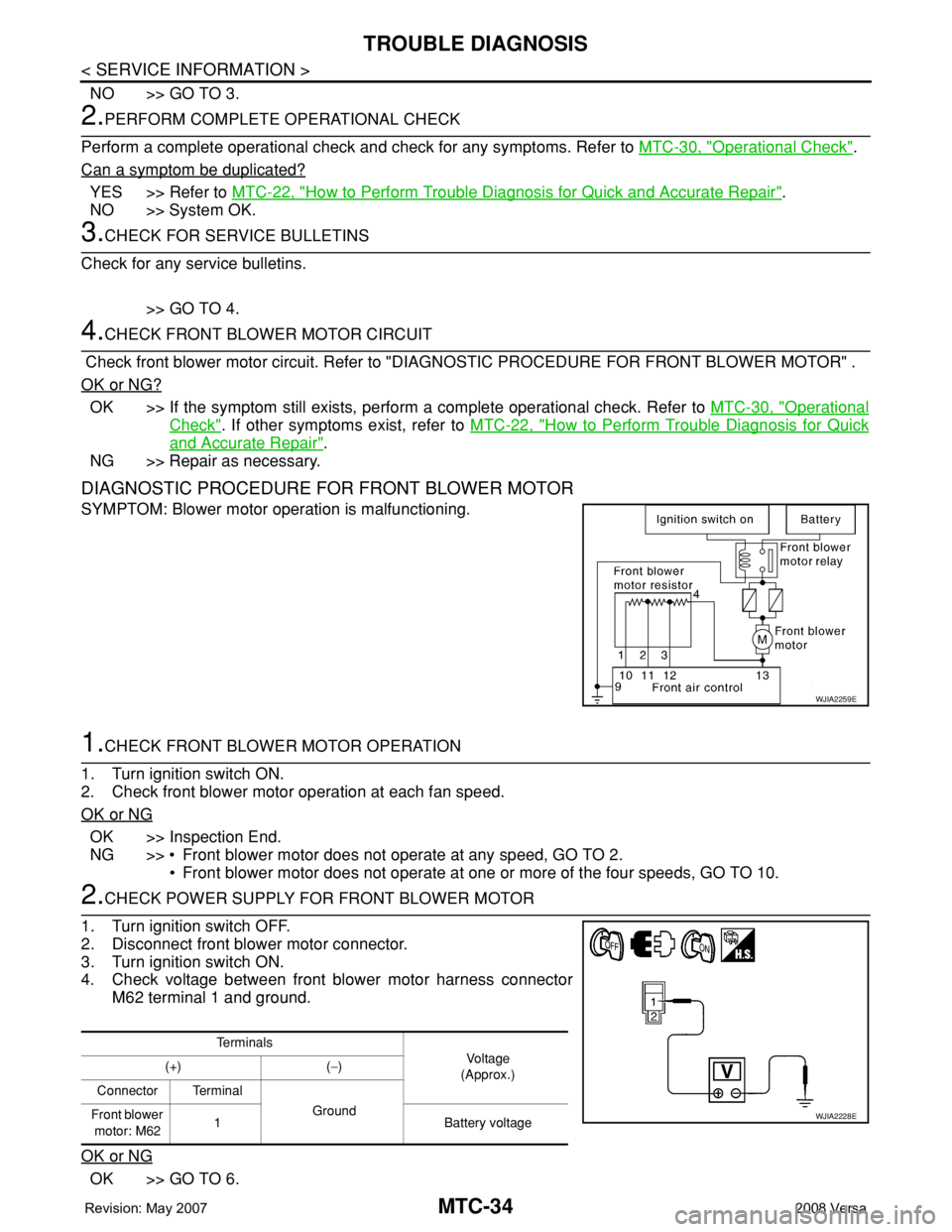
DIAGNOSTIC PROCEDURE FOR FRONT BLOWER MOTOR
SYMPTOM: Blower motor operation is malfunctioning.
1.CHECK FRONT BLOWER MOTOR OPERATION
1. Turn ignition switch ON.
2. Check front blower motor operation at each fan speed.
OK or NG
OK >> Inspection End.
NG >> • Front blower motor does not operate at any speed, GO TO 2.
• Front blower motor does not operate at one or more of the four speeds, GO TO 10.
2.CHECK POWER SUPPLY FOR FRONT BLOWER MOTOR
1. Turn ignition switch OFF.
2. Disconnect front blower motor connector.
3. Turn ignition switch ON.
4. Check voltage between front blower motor harness connector
M62 terminal 1 and ground.
OK or NG
OK >> GO TO 6.
WJIA2259E
Te r m i n a l s
Vo l ta g e
(Approx.) (+) (−)
Connector Terminal
Ground
Front blower
motor: M621 Battery voltage
WJIA2228E
Page 2376 of 2771
MTC-38
< SERVICE INFORMATION >
TROUBLE DIAGNOSIS
Perform diagnostic procedure for the magnetic clutch. Refer to "DIAGNOSTIC PROCEDURE FOR MAGNET
CLUTCH".
OK or NG
OK >> If the symptom still exists, perform a complete operational check. Refer to MTC-30, "Operational
Check". If other symptoms exist, refer to MTC-22, "How to Perform Trouble Diagnosis for Quick
and Accurate Repair".
NG >> Repair as necessary.
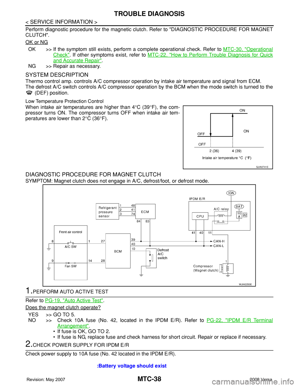
SYSTEM DESCRIPTION
Thermo control amp. controls A/C compressor operation by intake air temperature and signal from ECM.
The defrost A/C switch controls A/C compressor operation by the BCM when the mode switch is turned to the
(DEF) position.
Low Temperature Protection Control
When intake air temperatures are higher than 4°C (39°F), the com-
pressor turns ON. The compressor turns OFF when intake air tem-
peratures are lower than 2°C (36°F).
DIAGNOSTIC PROCEDURE FOR MAGNET CLUTCH
SYMPTOM: Magnet clutch does not engage in A/C, defrost/foot, or defrost mode.
1.PERFORM AUTO ACTIVE TEST
Refer to PG-19, "
Auto Active Test".
Does the magnet clutch operate?
YES >> GO TO 5.
NO >> Check 10A fuse (No. 42, located in the IPDM E/R). Refer to PG-22, "
IPDM E/R Terminal
Arrangement".
• If fuse is OK, GO TO 2.
• If fuse is NG, replace fuse and check harness for short circuit. Repair or replace if necessary.
2.CHECK POWER SUPPLY FOR IPDM E/R
Check power supply to 10A fuse (No. 42 located in the IPDM E/R).
SJIA0741E
WJIA2250E
:Battery voltage should exist
Page 2450 of 2771
IPDM E/R (INTELLIGENT POWER DISTRIBUTION MODULE ENGINE ROOM)
PG-17
< SERVICE INFORMATION >
C
D
E
F
G
H
I
J
L
MA
B
PG
N
O
P
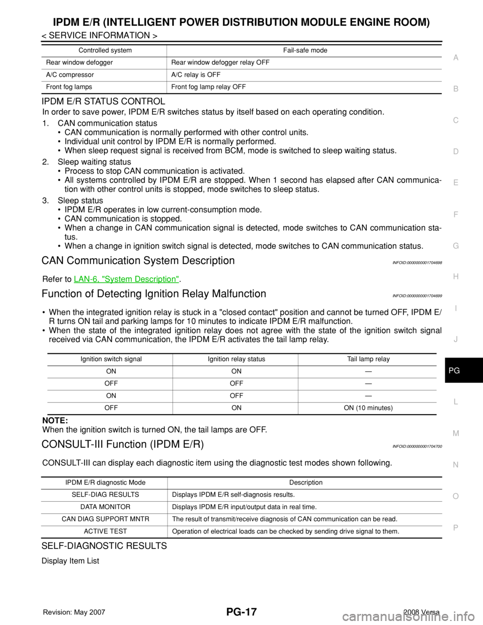
IPDM E/R STATUS CONTROL
In order to save power, IPDM E/R switches status by itself based on each operating condition.
1. CAN communication status
• CAN communication is normally performed with other control units.
• Individual unit control by IPDM E/R is normally performed.
• When sleep request signal is received from BCM, mode is switched to sleep waiting status.
2. Sleep waiting status
• Process to stop CAN communication is activated.
• All systems controlled by IPDM E/R are stopped. When 1 second has elapsed after CAN communica-
tion with other control units is stopped, mode switches to sleep status.
3. Sleep status
• IPDM E/R operates in low current-consumption mode.
• CAN communication is stopped.
• When a change in CAN communication signal is detected, mode switches to CAN communication sta-
tus.
• When a change in ignition switch signal is detected, mode switches to CAN communication status.
CAN Communication System DescriptionINFOID:0000000001704698
Refer to LAN-6, "System Description".
Function of Detecting Ignition Relay MalfunctionINFOID:0000000001704699
• When the integrated ignition relay is stuck in a "closed contact" position and cannot be turned OFF, IPDM E/
R turns ON tail and parking lamps for 10 minutes to indicate IPDM E/R malfunction.
• When the state of the integrated ignition relay does not agree with the state of the ignition switch signal
received via CAN communication, the IPDM E/R activates the tail lamp relay.
NOTE:
When the ignition switch is turned ON, the tail lamps are OFF.
CONSULT-III Function (IPDM E/R)INFOID:0000000001704700
CONSULT-III can display each diagnostic item using the diagnostic test modes shown following.
SELF-DIAGNOSTIC RESULTS
Display Item List
Rear window defogger Rear window defogger relay OFF
A/C compressor A/C relay is OFF
Front fog lamps Front fog lamp relay OFFControlled system Fail-safe mode
Ignition switch signal Ignition relay status Tail lamp relay
ON ON —
OFF OFF —
ON OFF —
OFF ON ON (10 minutes)
IPDM E/R diagnostic Mode Description
SELF-DIAG RESULTS Displays IPDM E/R self-diagnosis results.
DATA MONITOR Displays IPDM E/R input/output data in real time.
CAN DIAG SUPPORT MNTR The result of transmit/receive diagnosis of CAN communication can be read.
ACTIVE TEST Operation of electrical loads can be checked by sending drive signal to them.
Page 2508 of 2771
PS-2
< SERVICE INFORMATION >
PRECAUTIONS
SERVICE INFORMATION
PRECAUTIONS
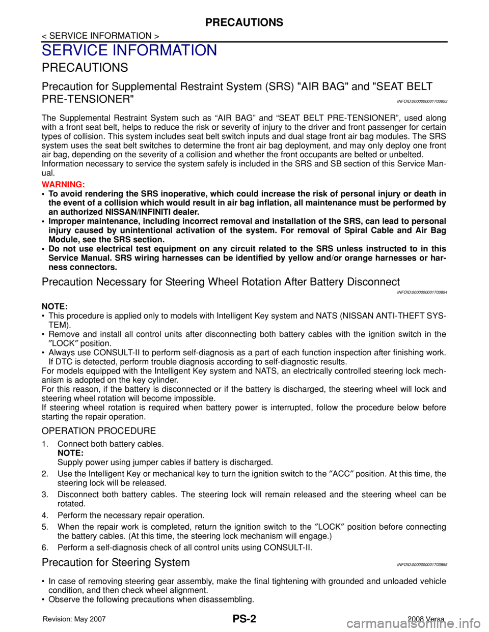
Precaution for Supplemental Restraint System (SRS) "AIR BAG" and "SEAT BELT
PRE-TENSIONER"
INFOID:0000000001703853
The Supplemental Restraint System such as “AIR BAG” and “SEAT BELT PRE-TENSIONER”, used along
with a front seat belt, helps to reduce the risk or severity of injury to the driver and front passenger for certain
types of collision. This system includes seat belt switch inputs and dual stage front air bag modules. The SRS
system uses the seat belt switches to determine the front air bag deployment, and may only deploy one front
air bag, depending on the severity of a collision and whether the front occupants are belted or unbelted.
Information necessary to service the system safely is included in the SRS and SB section of this Service Man-
ual.
WARNING:
• To avoid rendering the SRS inoperative, which could increase the risk of personal injury or death in
the event of a collision which would result in air bag inflation, all maintenance must be performed by
an authorized NISSAN/INFINITI dealer.
• Improper maintenance, including incorrect removal and installation of the SRS, can lead to personal
injury caused by unintentional activation of the system. For removal of Spiral Cable and Air Bag
Module, see the SRS section.
• Do not use electrical test equipment on any circuit related to the SRS unless instructed to in this
Service Manual. SRS wiring harnesses can be identified by yellow and/or orange harnesses or har-
ness connectors.
Precaution Necessary for Steering Wheel Rotation After Battery Disconnect
INFOID:0000000001703854
NOTE:
• This procedure is applied only to models with Intelligent Key system and NATS (NISSAN ANTI-THEFT SYS-
TEM).
• Remove and install all control units after disconnecting both battery cables with the ignition switch in the
″LOCK″ position.
• Always use CONSULT-II to perform self-diagnosis as a part of each function inspection after finishing work.
If DTC is detected, perform trouble diagnosis according to self-diagnostic results.
For models equipped with the Intelligent Key system and NATS, an electrically controlled steering lock mech-
anism is adopted on the key cylinder.
For this reason, if the battery is disconnected or if the battery is discharged, the steering wheel will lock and
steering wheel rotation will become impossible.
If steering wheel rotation is required when battery power is interrupted, follow the procedure below before
starting the repair operation.
OPERATION PROCEDURE
1. Connect both battery cables.
NOTE:
Supply power using jumper cables if battery is discharged.
2. Use the Intelligent Key or mechanical key to turn the ignition switch to the ″ACC″ position. At this time, the
steering lock will be released.
3. Disconnect both battery cables. The steering lock will remain released and the steering wheel can be
rotated.
4. Perform the necessary repair operation.
5. When the repair work is completed, return the ignition switch to the ″LOCK″ position before connecting
the battery cables. (At this time, the steering lock mechanism will engage.)
6. Perform a self-diagnosis check of all control units using CONSULT-II.
Precaution for Steering SystemINFOID:0000000001703855
• In case of removing steering gear assembly, make the final tightening with grounded and unloaded vehicle
condition, and then check wheel alignment.
• Observe the following precautions when disassembling.
Page 2531 of 2771

RF-1
BODY
C
D
E
F
G
H
J
K
L
M
SECTION RF
A
B
RF
N
O
P
CONTENTS
ROOF
PRECAUTION ...............................................2
PRECAUTIONS ...................................................2
Precaution for Supplemental Restraint System
(SRS) "AIR BAG" and "SEAT BELT PRE-TEN-
SIONER" ...................................................................
2
Precaution .................................................................2
PREPARATION ............................................3
PREPARATION ...................................................3
Commercial Service Tool ..........................................3
SYMPTOM DIAGNOSIS ...............................4
SQUEAK AND RATTLE TROUBLE DIAG-
NOSES ................................................................
4
Work Flow .................................................................4
Generic Squeak and Rattle Troubleshooting ............6
Diagnostic Worksheet ...............................................8
FUNCTION DIAGNOSIS ..............................10
TROUBLE DIAGNOSIS .....................................10
Component Parts and Harness Connector Loca-
tion ..........................................................................
10
System Description ..................................................10
CAN Communication System Description ...............12
Wiring Diagram - SROOF - ......................................13
Terminal and Reference Value for BCM ..................14
Terminal and Reference Value for Sunroof Motor
Assembly .................................................................
15
Work Flow ................................................................15
CONSULT-III Function (BCM) .................................15
Work Support ...........................................................16
Active Test ...............................................................16
Data Monitor ............................................................16
Trouble Diagnosis Chart by Symptom .....................16
BCM Power Supply and Ground Circuit Inspection
....
16
Sunroof Switch System Inspection ..........................16
Sunroof Motor Assembly Power Supply and
Ground Circuit Inspection ........................................
18
Door Switch Check ..................................................19
ON-VEHICLE REPAIR .................................21
SUNROOF .........................................................21
Removal and Installation .........................................21
Fitting Adjustment ....................................................26
Inspection ................................................................27