Page 657 of 2771

NATS (NISSAN ANTI-THEFT SYSTEM)
BL-223
< SERVICE INFORMATION >
C
D
E
F
G
H
J
K
L
MA
B
BL
N
O
P
OK or NG
OK >> BCM is malfunctioning.
• Replace BCM. Refer to BCS-18, "
Removal and Instal-
lation of BCM" .
• Perform initialization with CONSULT-III
• For initialization, refer to “CONSULT-III Operation
Manual NATS”
NG >> Check the following.
• Harness for open or short between combination meter (security) and BCM
• Indicator lamp condition
Diagnosis Procedure 5INFOID:0000000001704116
Self-diagnostic results:
“LOCK MODE” displayed on CONSULT-III screen
1.CONFIRM SELF-DIAGNOSTIC RESULTS
Confirm SELF-DIAGNOSTIC RESULTS “LOCK MODE” is displayed on CONSULT-III screen.
Is
“LOCK MODE” displayed?
Yes >> GO TO 2.
No >> GO TO BL-217, "
Trouble Diagnosis" .
2.ESCAPE FROM LOCK MODE
1. Turn ignition switch OFF.
2. Turn ignition switch ON with registered key. (Do not start engine.) Wait 5 seconds.
3. Return the key to OFF position. Wait 5 seconds.
4. Repeat steps 2 and 3 twice (total of three cycles).
5. Start the engine.
Does engine start?
Yes >> System is OK (Now system is escaped from “LOCK MODE”).
No >> GO TO 3.
3.PERFORM INITIALIZATION WITH CONSULT-III
Perform initialization with CONSULT-III.
For initialization, refer to “CONSULT-III Operation Manual NATS”.
NOTE:
If the initialization is not completed or malfunctions, CONSULT-III shows the message on the screen.
Can the system be initialized?
Yes >> System is OK.
No >> GO TO 4.
4.PERFORM INITIALIZATION WITH CONSULT-III AGAIN
1. Replace BCM.
2. Perform initialization with CONSULT-III.
For initialization, refer to “CONSULT-III Operation Manual NATS”.
NOTE:
If the initialization is not completed or malfunctions, CONSULT-III shows the message on the screen.
Can the system be initialized?
Yes >> System is OK. (BCM is malfunctioning.)
No >> ECM is malfunctioning.
• Replace ECM.
• Perform initialization with CONSULT-III
• For initialization, refer to “CONSULT-III Operation Manual NATS”
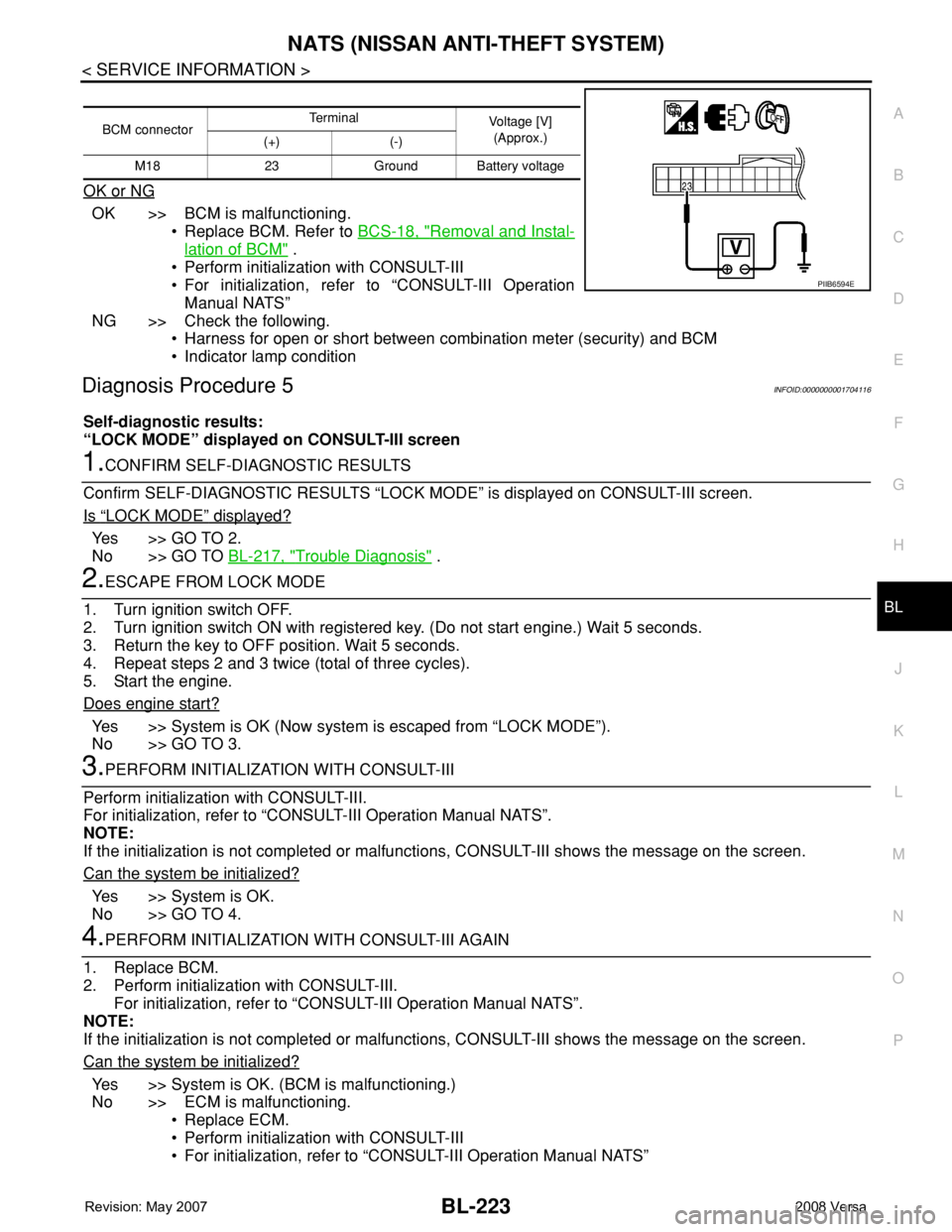
BCM connectorTerminal
Voltage [V]
(Approx.)
(+) (-)
M18 23 Ground Battery voltage
PIIB6594E
Page 662 of 2771

BL-228
< SERVICE INFORMATION >
BODY REPAIR
4. Front pillar inner reinforcement (RH&LH)
5. Lower dash reinforcement
6. 4th crossmember (RH&LH)
7. Front side member rear extension (RH&LH)
8. 3rd crossmember (RH&LH)
9. Front seat outer rear bracket (RH&LH)
10. Front seat inner rear bracket (RH&LH)
11. 2nd crossmember (RH&LH)
12. Front seat outer front bracket (RH&LH)
13. Front seat inner front bracket (RH&LH)
14. Fender bracket (RH&LH)
15. Strut housing assembly RH
16. Cowl top side upper (RH&LH)
17. Front strut housing (RH&LH)
18. Upper torque rod reinforcement
19. Closing plate assembly RH
20. Engine mount reinforcement
21. Strut tower front reinforcement RH
22. Front hoodledge lower RH
23. Frame bracket outer (RH&LH)
24. Front bumper support bracket (RH&LH)
25. Closing plate (RH&LH)
26. Front suspension rear bracket (RH&LH)
27. Front side member outrigger (RH&LH)
28. Front side member assembly (RH&LH)
29. Front side member (RH&LH)
30. Frame bracket (RH&LH)
31. Closing plate assembly LH
32. Hoodledge connector (RH&LH)
33. Radiator core side support (RH&LH)
34. Radiator core support upper (RH&LH)
35. Hoodledge upper (RH&LH)
36. Hoodledge reinforcement assembly (RH&LH)
37. Dash side (RH&LH)
38. Dash side assembly (RH& LH)
39. Front floor reinforcement (RH&LH)
40. Front floor front (RH&LH)
41. Front floor center
42. Rear seat crossmember
43. Rear center crossmember
44. Rear seat upper crossmember
45. Rear side member (RH&LH)
46. Sill inner extension (RH&LH)
47. Rear side member extension (RH&LH)
48. Rear side member assembly (RH & LH)
49. Rear floor front
50. Rear floor front assembly
51. Rear floor side (RH&LH)
52. Rear floor rear
Page 710 of 2771
BL-276
< SERVICE INFORMATION >
BODY REPAIR
HOODLEDGE RH
• Work after radiator core support upper and lower have been removed.
Change Parts
●Hoodledge reinforcement assembly●Front strut housing●Fender bracket
●Cowl top side upper●Hoodledge upper●Hoodledge connector
LIIA2893E
Page 711 of 2771
BODY REPAIR
BL-277
< SERVICE INFORMATION >
C
D
E
F
G
H
J
K
L
MA
B
BL
N
O
P
FRONT SIDE MEMBER
• Work after hoodledge and radiator core support have been removed.
Change Parts
●Hoodledge reinforcement assembly●Front strut housing●Fender bracket
●Cowl top side upper●Hoodledge upper●Hoodledge connector
LIIA2894E
Page 712 of 2771
BL-278
< SERVICE INFORMATION >
BODY REPAIR
FRONT SIDE MEMBER PARTIAL
LH
• Work after radiator core support and hoodledge connector have been removed.
Change parts
●Front side member●Front side member closing plate●Front side member outrigger
●Frame bracket outer
LIIA2895E
Page 713 of 2771
BODY REPAIR
BL-279
< SERVICE INFORMATION >
C
D
E
F
G
H
J
K
L
MA
B
BL
N
O
P
RH
• Work after radiator core support and hoodledge connector have been removed.
Change parts
●Front side member partial●Front side member closing plate par-
tial●Frame bracket outer
●Frame bracket
WIIA1393E
Page 733 of 2771

BR-2
< SERVICE INFORMATION >
PRECAUTIONS
SERVICE INFORMATION
PRECAUTIONS
Precaution for Supplemental Restraint System (SRS) "AIR BAG" and "SEAT BELT
PRE-TENSIONER"
INFOID:0000000001703775
The Supplemental Restraint System such as “AIR BAG” and “SEAT BELT PRE-TENSIONER”, used along
with a front seat belt, helps to reduce the risk or severity of injury to the driver and front passenger for certain
types of collision. This system includes seat belt switch inputs and dual stage front air bag modules. The SRS
system uses the seat belt switches to determine the front air bag deployment, and may only deploy one front
air bag, depending on the severity of a collision and whether the front occupants are belted or unbelted.
Information necessary to service the system safely is included in the SRS and SB section of this Service Man-
ual.
WARNING:
• To avoid rendering the SRS inoperative, which could increase the risk of personal injury or death in
the event of a collision which would result in air bag inflation, all maintenance must be performed by
an authorized NISSAN/INFINITI dealer.
• Improper maintenance, including incorrect removal and installation of the SRS, can lead to personal
injury caused by unintentional activation of the system. For removal of Spiral Cable and Air Bag
Module, see the SRS section.
• Do not use electrical test equipment on any circuit related to the SRS unless instructed to in this
Service Manual. SRS wiring harnesses can be identified by yellow and/or orange harnesses or har-
ness connectors.
Precaution for Brake SystemINFOID:0000000001703776
• Refill using recommended brake fluid. Refer to MA-10.
• Never reuse drained brake fluid.
• Be careful not to splash brake fluid on painted surface of body. If brake fluid is splashed on painted surfaces
of body immediately wipe it off with cloth and then wash it away with water.
• To clean or wash all parts of master cylinder, disc brake caliper and wheel cylinder, use new brake fluid.
• Never use mineral oils such as gasoline or kerosene. They will ruin rubber parts of the hydraulic system.
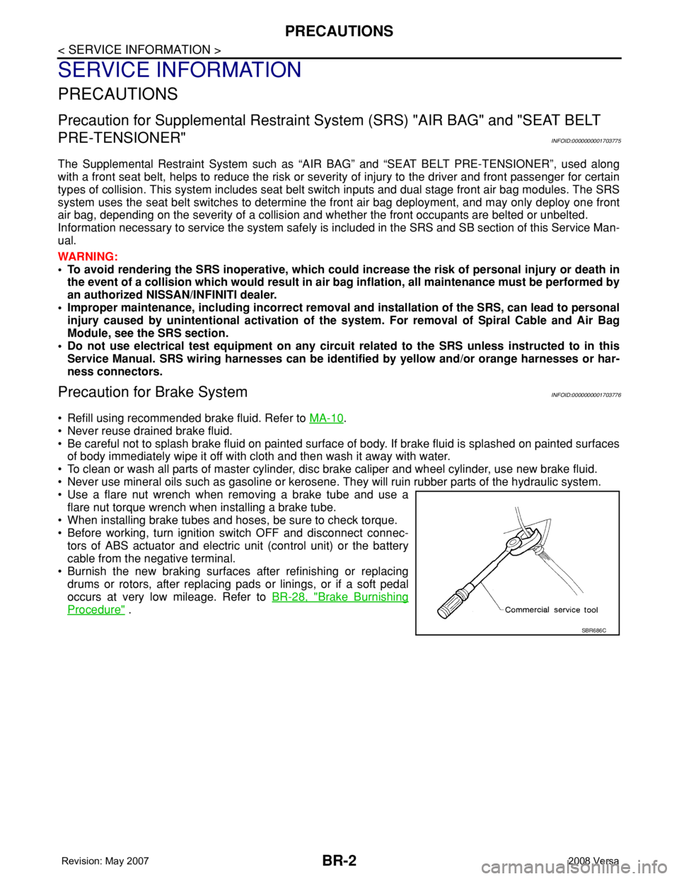
• Use a flare nut wrench when removing a brake tube and use a
flare nut torque wrench when installing a brake tube.
• When installing brake tubes and hoses, be sure to check torque.
• Before working, turn ignition switch OFF and disconnect connec-
tors of ABS actuator and electric unit (control unit) or the battery
cable from the negative terminal.
• Burnish the new braking surfaces after refinishing or replacing
drums or rotors, after replacing pads or linings, or if a soft pedal
occurs at very low mileage. Refer toBR-28, "
Brake Burnishing
Procedure" .
SBR686C
Page 739 of 2771

BR-8
< SERVICE INFORMATION >
BRAKE FLUID
BRAKE FLUID
On Board InspectionINFOID:0000000001703781
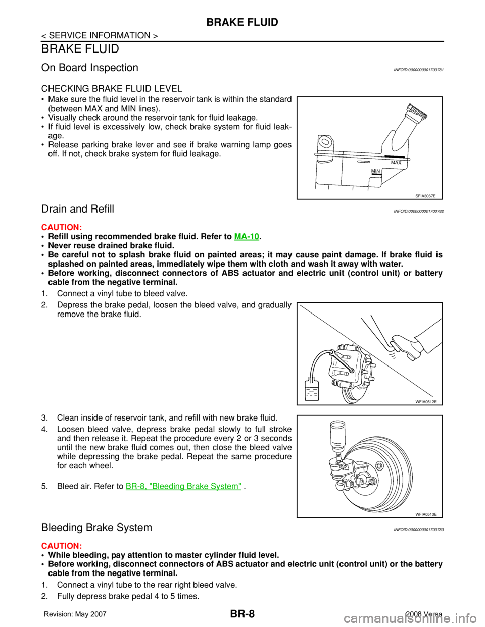
CHECKING BRAKE FLUID LEVEL
• Make sure the fluid level in the reservoir tank is within the standard
(between MAX and MIN lines).
• Visually check around the reservoir tank for fluid leakage.
• If fluid level is excessively low, check brake system for fluid leak-
age.
• Release parking brake lever and see if brake warning lamp goes
off. If not, check brake system for fluid leakage.
Drain and RefillINFOID:0000000001703782
CAUTION:
• Refill using recommended brake fluid. Refer to MA-10
.
• Never reuse drained brake fluid.
• Be careful not to splash brake fluid on painted areas; it may cause paint damage. If brake fluid is
splashed on painted areas, immediately wipe them with cloth and wash it away with water.
• Before working, disconnect connectors of ABS actuator and electric unit (control unit) or battery
cable from the negative terminal.
1. Connect a vinyl tube to bleed valve.
2. Depress the brake pedal, loosen the bleed valve, and gradually
remove the brake fluid.
3. Clean inside of reservoir tank, and refill with new brake fluid.
4. Loosen bleed valve, depress brake pedal slowly to full stroke
and then release it. Repeat the procedure every 2 or 3 seconds
until the new brake fluid comes out, then close the bleed valve
while depressing the brake pedal. Repeat the same procedure
for each wheel.
5. Bleed air. Refer to BR-8, "
Bleeding Brake System" .
Bleeding Brake SystemINFOID:0000000001703783
CAUTION:
• While bleeding, pay attention to master cylinder fluid level.
• Before working, disconnect connectors of ABS actuator and electric unit (control unit) or the battery
cable from the negative terminal.
1. Connect a vinyl tube to the rear right bleed valve.
2. Fully depress brake pedal 4 to 5 times.
SFIA3067E
WFIA0512E
WFIA0513E