2008 NISSAN TIIDA transmission input sensor
[x] Cancel search: transmission input sensorPage 957 of 2771
CVT-118
< SERVICE INFORMATION >
DTC P0845 TRANSMISSION FLUID PRESSURE SENSOR B CIRCUIT (PRI
PRESSURE SENSOR)
OK or NG
OK >> Replace TCM. Refer to CVT-8, "Service After Replacing TCM and Transaxle Assembly" .
NG >> Repair open circuit or short to ground or short to power in harness or connectors.
4.CHECK HARNESS BETWEEN TCM AND TRANSMISSION FLUID PRESSURE SENSOR B (PRIMARY
PRESSURE SENSOR)
1. Turn ignition switch OFF.
2. Disconnect TCM connector and CVT unit harness connector.
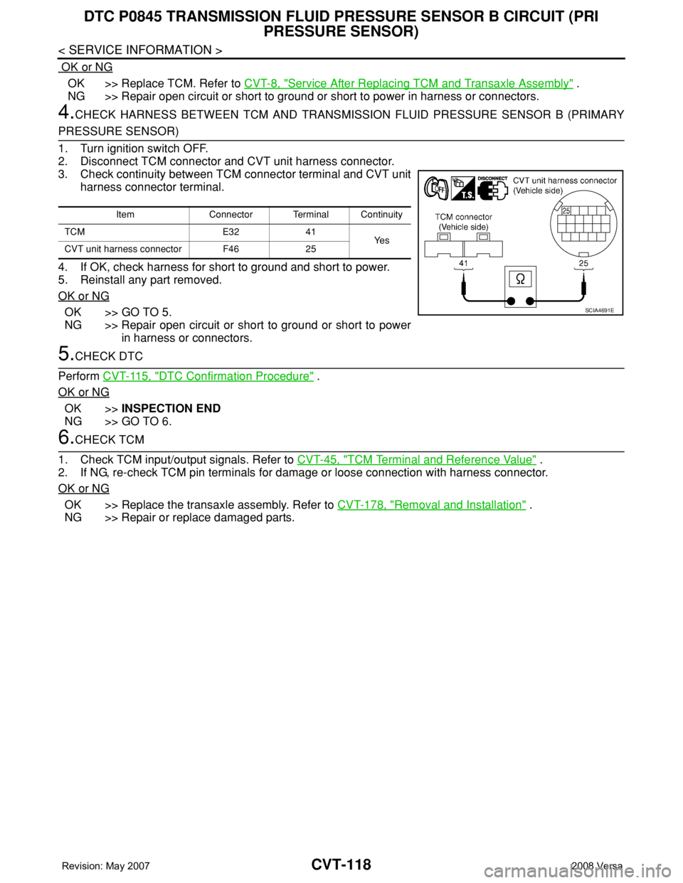
3. Check continuity between TCM connector terminal and CVT unit
harness connector terminal.
4. If OK, check harness for short to ground and short to power.
5. Reinstall any part removed.
OK or NG
OK >> GO TO 5.
NG >> Repair open circuit or short to ground or short to power
in harness or connectors.
5.CHECK DTC
Perform CVT-115, "
DTC Confirmation Procedure" .
OK or NG
OK >>INSPECTION END
NG >> GO TO 6.
6.CHECK TCM
1. Check TCM input/output signals. Refer to CVT-45, "
TCM Terminal and Reference Value" .
2. If NG, re-check TCM pin terminals for damage or loose connection with harness connector.
OK or NG
OK >> Replace the transaxle assembly. Refer to CVT-178, "Removal and Installation" .
NG >> Repair or replace damaged parts.
Item Connector Terminal Continuity
TCM E32 41
Ye s
CVT unit harness connector F46 25
SCIA4691E
Page 958 of 2771

DTC P0868 SECONDARY PRESSURE DOWN
CVT-119
< SERVICE INFORMATION >
D
E
F
G
H
I
J
K
L
MA
B
CVT
N
O
P
DTC P0868 SECONDARY PRESSURE DOWN
DescriptionINFOID:0000000001703593
• The pressure control solenoid valve B (secondary pressure solenoid valve) is included in the control valve
assembly.
• The pressure control solenoid valve B (secondary pressure solenoid valve) regulates the secondary pres-
sure to suit the driving condition in response to a signal sent from the TCM.
CONSULT-III Reference Value in Data Monitor ModeINFOID:0000000001703594
Remarks: Specification data are reference values.
On Board Diagnosis LogicINFOID:0000000001703595
• This is not an OBD-II self-diagnostic item.
• Diagnostic trouble code “P0868 SEC/PRESS DOWN” with CONSULT-III is detected when secondary fluid
pressure is too low compared with the commanded value while driving.
Possible CauseINFOID:0000000001703596
• Harness or connectors
(Solenoid circuit is open or shorted.)
• Pressure control solenoid valve B (Secondary pressure solenoid valve) system
• Transmission fluid pressure sensor A (Secondary pressure sensor)
• Line pressure control system
DTC Confirmation ProcedureINFOID:0000000001703597
CAUTION:
Always drive vehicle at a safe speed.
NOTE:
If “DTC Confirmation Procedure” has been previously performed, always turn ignition switch OFF and
wait at least 10 seconds before performing the next test.
After the repair, perform the following procedure to confirm the malfunction is eliminated.
WITH CONSULT-III
1. Turn ignition switch ON and select “DATA MONITOR” mode for “TRANSMISSION” with CONSULT-III.
2. Make sure that output voltage of CVT fluid temperature sensor is within the range below.
ATF TEMP SEN: 1.0 - 2.0 V
If out of range, drive the vehicle to decrease the voltage (warm up the fluid) or stop engine to
increase the voltage (cool down the fluid)
3. Start engine and maintain the following conditions for at least 10 consecutive seconds.
VEHICLE SPEED (accelerate slowly): 0 → 50 km/h (31 MPH)
ACC PEDAL OPEN: 0.5/8 - 1.0/8
RANGE: “D” position
4. If DTC is detected, go to CVT-119, "
Diagnosis Procedure".
Diagnosis ProcedureINFOID:0000000001703598
1.CHECK INPUT SIGNAL
With CONSULT-III
1. Start engine.
2. Select “MAIN SIGNALS” in “DATA MONITOR” mode for “TRANSMISSION” with CONSULT-III.
3. Start vehicle and read out the value of “SEC PRESS”.
Item name Condition Display value (Approx.)
SEC PRESS “N” position idle 0.8 MPa
Item name Condition Display value (Approx.)
SEC PRESS “N” position idle 0.8 MPa
Page 964 of 2771
DTC P1705 THROTTLE POSITION SENSOR
CVT-125
< SERVICE INFORMATION >
D
E
F
G
H
I
J
K
L
MA
B
CVT
N
O
P
DTC P1705 THROTTLE POSITION SENSOR
DescriptionINFOID:0000000001703605
Electric throttle control actuator consists of throttle control motor, accelerator pedal position sensor, throttle
position sensor etc. The actuator sends a signal to the ECM, and ECM sends the signal to TCM with CAN
communication.
CONSULT-III Reference Value in Data Monitor ModeINFOID:0000000001703606
Remarks: Specification data are reference values.
On Board Diagnosis LogicINFOID:0000000001703607
• This is not an OBD-II self-diagnostic item.
• Diagnostic trouble code “P1705 TP SEN/CIRC A/T” with CONSULT-III is detected when TCM does not
receive the proper accelerator pedal position signals (input by CAN communication) from ECM.
Possible CauseINFOID:0000000001703608
•ECM
• Harness or connectors
(CAN communication line is open or shorted.)
DTC Confirmation ProcedureINFOID:0000000001703609
NOTE:
If “DTC Confirmation Procedure” has been previously performed, always turn ignition switch OFF and
wait at least 10 seconds before performing the next test.
After the repair, perform the following procedure to confirm the malfunction is eliminated.
WITH CONSULT-III
1. Turn ignition switch ON. (Do not start engine.)
2. Select “DATA MONITOR” mode for “TRANSMISSION” with CONSULT-III.
3. Depress accelerator pedal fully and release it, then wait for 5 seconds.
4. If DTC is detected, go to CVT-125, "
Diagnosis Procedure".
Diagnosis ProcedureINFOID:0000000001703610
1.CHECK CAN COMMUNICATION LINE
Perform the self-diagnosis check. Refer to CVT-47, "
CONSULT-III Function (TRANSMISSION)".
Is any malfunction of the
“U1000 CAN COMM CIRCUIT” indicated?
YES >> Check the CAN communication line. Refer to CVT-56.
NO >> GO TO 2.
2.CHECK INPUT SIGNAL
With CONSULT-III
1. Turn ignition switch ON. (Do not start engine.)
2. Select “ECU INPUT SIGNALS” in “DATA MONITOR” mode for “TRANSMISSION” with CONSULT-III.
3. Read out the value of “ACC PEDAL OPEN”.
OK or NG
Item name Condition Display value (Approx.)
ACC PEDAL OPEN Released accelerator pedal - Fully depressed accelerator pedal 0.0/8 - 8.0/8
Item name Condition Display value (Approx.)
ACC PEDAL OPEN Release accelerator ped-
al.
↓
Fully depressed acceler-
ator pedal0.0/8
↓
8.0/8
Page 966 of 2771
DTC P1722 ESTM VEHICLE SPEED SIGNAL
CVT-127
< SERVICE INFORMATION >
D
E
F
G
H
I
J
K
L
MA
B
CVT
N
O
P
DTC P1722 ESTM VEHICLE SPEED SIGNAL
DescriptionINFOID:0000000001703611
The vehicle speed signal is transmitted from ABS actuator and electric unit (control unit) to TCM by CAN com-
munication line.
CONSULT-III Reference Value in Data Monitor ModeINFOID:0000000001703612
Remarks: Specification data are reference values.
On Board Diagnosis LogicINFOID:0000000001703613
• This is not an OBD-II self-diagnostic item.
• Diagnostic trouble code “P1722 ESTM VEH SPD SIG” with CONSULT-III is detected when TCM does not
receive the proper vehicle speed signal (input by CAN communication) from ABS actuator and electric unit
(control unit).
Possible CauseINFOID:0000000001703614
• Harness or connectors
(Sensor circuit is open or shorted.)
• ABS actuator and electric unit (control unit)
DTC Confirmation ProcedureINFOID:0000000001703615
CAUTION:
Always drive vehicle at a safe speed.
NOTE:
If “DTC Confirmation Procedure” has been previously performed, always turn ignition switch OFF and
wait at least 10 seconds before performing the next test.
After the repair, touch “ERASE” on “SELF-DIAG RESULTS” and then perform the following procedure to con-
firm the malfunction is eliminated.
WITH CONSULT-III
1. Turn ignition switch ON. (Do not start engine.)
2. Select “DATA MONITOR” mode for “TRANSMISSION” with CONSULT-III.
3. Start engine and maintain the following conditions for at least 5 consecutive seconds.
ACC PEDAL OPEN: 1.0/8 or less
VEHICLE SPEED SE: 30 km/h (17 MPH) or more
4. If DTC is detected, go to CVT-127, "
Diagnosis Procedure".
Diagnosis ProcedureINFOID:0000000001703616
1.CHECK CAN COMMUNICATION LINE
Perform the self-diagnosis check. Refer to CVT-47, "
CONSULT-III Function (TRANSMISSION)".
Is any malfunction of the
“U1000 CAN COMM CIRCUIT” indicated?
YES >> Check CAN communication line. Refer to CVT-56.
NO >> GO TO 2.
2.CHECK ABS ACTUATOR AND ELECTRIC UNIT (CONTROL UNIT)
Perform ABS actuator and electric unit (control unit) self-diagnosis check. Refer to BRC-18, "
CONSULT-III
Function (ABS)".
OK or NG
OK >> GO TO 3.
NG >> Repair or replace damaged parts.
Item name Condition Display value
ESTM VSP SIG
During driving Approximately matches the speedometer reading.
VEHICLE SPEED
Page 968 of 2771

DTC P1723 CVT SPEED SENSOR FUNCTION
CVT-129
< SERVICE INFORMATION >
D
E
F
G
H
I
J
K
L
MA
B
CVT
N
O
P
DTC P1723 CVT SPEED SENSOR FUNCTION
DescriptionINFOID:0000000001703617
• The input speed sensor (primary speed sensor) is included in the control valve assembly.
• The vehicle speed sensor CVT [output speed sensor (secondary speed sensor)] detects the revolution of the
idler gear and generates a pulse signal. The pulse signal is sent to the TCM, which converts it into vehicle
speed.
• The input speed sensor (primary speed sensor) detects the primary pulley revolution speed and sends a sig-
nal to the TCM.
On Board Diagnosis LogicINFOID:0000000001703618
• This is not an OBD-II self-diagnostic item.
• Diagnostic trouble code “P1723 CVT SPD SEN/FNCTN” with CONSULT-III is detected when there is a great
difference between the vehicle speed signal and the secondary speed sensor signal.
CAUTION:
One of the “P0720 VEH SPD SEN/CIR AT”, the “P0715 INPUT SPD SEN/CIRC” or the “P0725 ENGINE
SPEED SIG“ is displayed with the DTC at the same time.
Possible CauseINFOID:0000000001703619
• Harness or connectors
(Sensor circuit is open or shorted.)
• Output speed sensor (Secondary speed sensor)
• Input speed sensor (Primary speed sensor)
• Engine speed signal system
DTC Confirmation ProcedureINFOID:0000000001703620
CAUTION:
Always drive vehicle at a safe speed.
NOTE:
If “DTC Confirmation Procedure” has been previously performed, always turn ignition switch OFF and
wait at least 10 seconds before performing the next test.
After the repair, touch “ERASE” on “SELF-DIAG RESULTS” and then perform the following procedure to con-
firm the malfunction is eliminated.
WITH CONSULT-III
1. Turn ignition switch ON and select “DATA MONITOR” mode for “TRANSMISSION” with CONSULT-III.
2. Start engine and maintain the following conditions for at least 5 consecutive seconds.
VEHICLE SPEED SE: 10 km/h (6 MPH) or more
ACC PEDAL OPEN: More than 1.0/8
RANGE: “D” position
ENG SPEED: 450 rpm or more
Driving location: Driving the vehicle uphill (increased engine load) will help maintain the driving
conditions required for this test.
3. If DTC is detected, go to CVT-129, "
Diagnosis Procedure".
Diagnosis ProcedureINFOID:0000000001703621
1.CHECK STEP MOTOR FUNCTION
Perform the self-diagnosis check. Refer to CVT-47, "
CONSULT-III Function (TRANSMISSION)".
Is a malfunction in the step motor function indicated in the results?
YES >> Repair or replace damaged parts. (Check the step motor function. Refer to CVT-141.)
NO >> GO TO 2.
2.CHECK OUTPUT SPEED SENSOR (SECONDARY SPEED SENSOR SYSTEM) AND INPUT SPEED
SENSOR (PRIMARY SPEED SENSOR) SYSTEM
Check output speed sensor (secondary speed sensor) system and input speed sensor (primary speed sensor)
system. Refer to CVT-80
, CVT-76.
Page 1032 of 2771
COMBINATION METERS
DI-11
< SERVICE INFORMATION >
C
D
E
F
G
H
I
J
L
MA
B
DI
N
O
P
Self-Diagnosis Mode of Combination MeterINFOID:0000000001704497
SELF-DIAGNOSIS MODE FUNCTION
• Self-diagnosis can check for continuity between meter control circuit and each meter (speedometer, tachom-
eter and fuel gauge).
• Self-diagnosis can check for odo/trip meter and A/T indicator (with A/T) or CVT indicator (with CVT) seg-
ment, low-fuel level warning lamp, low water temperature indicator lamp, and high water temperature warn-
ing lamp.
OPERATION PROCEDURE
1. Turn the ignition switch ON, and switch the odo/trip meter to “trip A” or “trip B”.
NOTE:
13 B Illumination control switch (-) — — Refer to LT- 1 0 5 , "System Description" .
17 GWasher fluid level switch
(Canada models)ONWasher fluid level low 0
Washer fluid level normal Battery voltage
21
BGround — — 0 22
23
24 V Fuel level sensor ground (-) ON — 0
26 BVehicle speed sensor ground
(without ABS or CVT)ON — 0
27 G Battery power supply OFF — Battery voltage
28 SB Ignition switch ON or START ON — Battery voltage
29 GR Seat belt buckle switch RH ONUnfastened (ON) 0
Fastened (OFF) Battery voltage
30 G Stop lamp switch ONBrake pedal depressed Battery voltage
Brake pedal released 0
31 V A/T N-range input (with A/T) ONTransmission gear selector lever
in N positionBattery voltage
Transmission gear selector lever
other than N position0
32 W A/T P-range input (with A/T) ONTransmission gear selector lever
in P positionBattery voltage
Transmission gear selector lever
other than P position0
33 Y A/T PN output (with A/T) ONTransmission gear selector lever
in P or N position0
Transmission gear selector lever
other than P or N positionBattery voltage
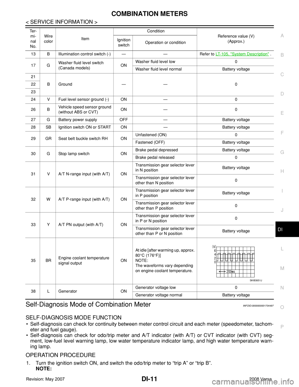
35 BREngine coolant temperature
signal outputONAt idle [after warming up, approx.
80°C (176°F)]
NOTE:
The waveforms vary depending
on engine coolant temperature.
38 L Generator ONGenerator voltage low 0
Generator voltage normal Battery voltage Te r -
mi-
nal
No.Wire
colorItemCondition
Reference value (V)
(Approx.) Ignition
switchOperation or condition
SKIB3651J
Page 1038 of 2771

COMBINATION METERS
DI-17
< SERVICE INFORMATION >
C
D
E
F
G
H
I
J
L
MA
B
DI
N
O
P
OK or NG
OK >> Check harness or connector between combination meter and vehicle speed sensor.
NG >> Replace vehicle speed sensor.
WITH CVT, WITHOUT ABS
1.CHECK COMBINATION METER INPUT SIGNAL
1. Start engine and select “METER/M&A” on CONSULT-III.
2. Using “SPEED METER” on “DATA MONITOR”, compare the value of “DATA MONITOR” with speedome-
ter pointer of combination meter.
OK or NG
OK >> Perform TCM self-diagnosis. Refer to CVT-47, "CONSULT-III Function (TRANSMISSION)" .
NG >> Replace combination meter. Refer to IP-11, "
Removal and Installation" .
Engine Speed Signal InspectionINFOID:0000000001704503
Symptom: Improper tachometer indication.
1.CHECK COMBINATION METER INPUT SIGNAL
1. Start engine and select “METER/M&A” on CONSULT-III.
2. Using “TACHO METER” on “DATA MONITOR”, compare the value of “DATA MONITOR” with tachometer
pointer of combination meter.
OK or NG
OK >> Perform ECM self-diagnosis. Refer to EC-109, "CONSULT-II Function (ENGINE)" .
NG >> Replace combination meter. Refer to IP-11, "
Removal and Installation" .
Fuel Level Sensor Signal InspectionINFOID:0000000001704504
Symptom:
• Improper fuel gauge indication.
• Low-fuel warning lamp indication is irregular.
NOTE:
The following symptoms do not indicate a malfunction.
• Depending on vehicle position or driving circumstance, the fuel level in the tank shifts and the indication may
fluctuate.
• If the vehicle is fueled with the ignition switch ON, the indication will update slowly.
• If the vehicle is tilted when the ignition switch is turned ON, fuel in the tank may flow to one direction result-
ing in a change of reading.
1.CHECK COMBINATION METER INPUT SIGNAL
1. Select “METER/M&A” on CONSULT-III.
2. Using “FUEL METER” on “DATA MONITOR”, compare the value of “DATA MONITOR” with fuel gauge
pointer of combination meter.
Te r m i n a l s
Resistance
value
(Approx.) (+) (–)
Component Terminal Component Terminal
Ve h i c l e
speed
sensor1Vehicle
speed
sensor2250Ω
Fuel gauge pointer Reference value of data monitor [lit.]
Full Approx. 49
3/4 Approx. 34
1/2 Approx. 22
1/4 Approx. 10
Empty Approx. 4
Page 1090 of 2771
EC-16
< SERVICE INFORMATION >
PRECAUTIONS
PRECAUTIONS
Precaution for Supplemental Restraint System (SRS) "AIR BAG" and "SEAT BELT
PRE-TENSIONER"
INFOID:0000000001702548
The Supplemental Restraint System such as “AIR BAG” and “SEAT BELT PRE-TENSIONER”, used along
with a front seat belt, helps to reduce the risk or severity of injury to the driver and front passenger for certain
types of collision. This system includes seat belt switch inputs and dual stage front air bag modules. The SRS
system uses the seat belt switches to determine the front air bag deployment, and may only deploy one front
air bag, depending on the severity of a collision and whether the front occupants are belted or unbelted.
Information necessary to service the system safely is included in the SRS and SB section of this Service Man-
ual.
WARNING:
• To avoid rendering the SRS inoperative, which could increase the risk of personal injury or death in
the event of a collision which would result in air bag inflation, all maintenance must be performed by
an authorized NISSAN/INFINITI dealer.
• Improper maintenance, including incorrect removal and installation of the SRS, can lead to personal
injury caused by unintentional activation of the system. For removal of Spiral Cable and Air Bag
Module, see the SRS section.
• Do not use electrical test equipment on any circuit related to the SRS unless instructed to in this
Service Manual. SRS wiring harnesses can be identified by yellow and/or orange harnesses or har-
ness connectors.
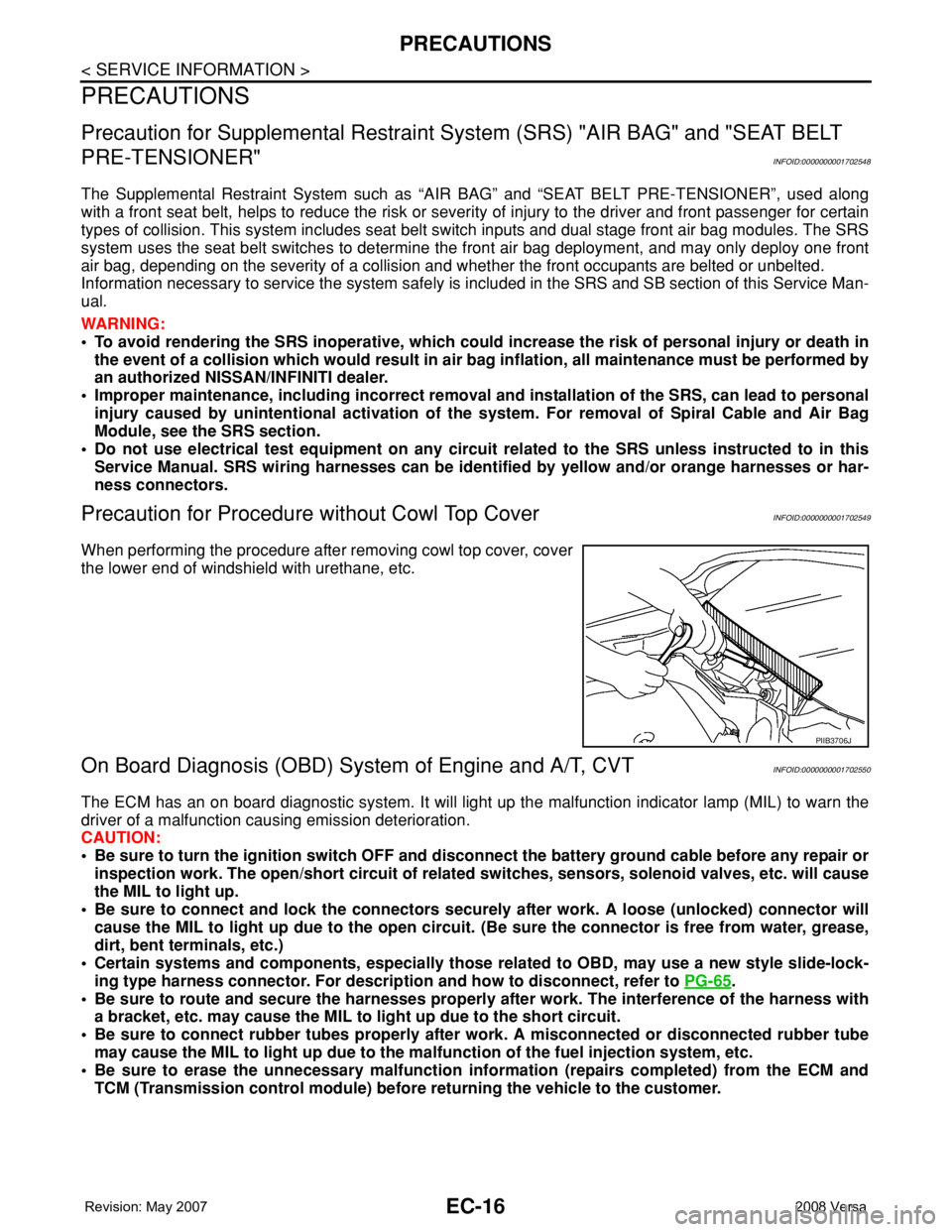
Precaution for Procedure without Cowl Top CoverINFOID:0000000001702549
When performing the procedure after removing cowl top cover, cover
the lower end of windshield with urethane, etc.
On Board Diagnosis (OBD) System of Engine and A/T, CVTINFOID:0000000001702550
The ECM has an on board diagnostic system. It will light up the malfunction indicator lamp (MIL) to warn the
driver of a malfunction causing emission deterioration.
CAUTION:
• Be sure to turn the ignition switch OFF and disconnect the battery ground cable before any repair or
inspection work. The open/short circuit of related switches, sensors, solenoid valves, etc. will cause
the MIL to light up.
• Be sure to connect and lock the connectors securely after work. A loose (unlocked) connector will
cause the MIL to light up due to the open circuit. (Be sure the connector is free from water, grease,
dirt, bent terminals, etc.)
• Certain systems and components, especially those related to OBD, may use a new style slide-lock-
ing type harness connector. For description and how to disconnect, refer to PG-65
.
• Be sure to route and secure the harnesses properly after work. The interference of the harness with
a bracket, etc. may cause the MIL to light up due to the short circuit.
• Be sure to connect rubber tubes properly after work. A misconnected or disconnected rubber tube
may cause the MIL to light up due to the malfunction of the fuel injection system, etc.
• Be sure to erase the unnecessary malfunction information (repairs completed) from the ECM and
TCM (Transmission control module) before returning the vehicle to the customer.
PIIB3706J