2008 NISSAN TIIDA transmission
[x] Cancel search: transmissionPage 353 of 2771

SERVICE DATA AND SPECIFICATIONS (SDS)
AT-341
< SERVICE INFORMATION >
D
E
F
G
H
I
J
K
L
MA
B
AT
N
O
P
SERVICE DATA AND SPECIFICATIONS (SDS)
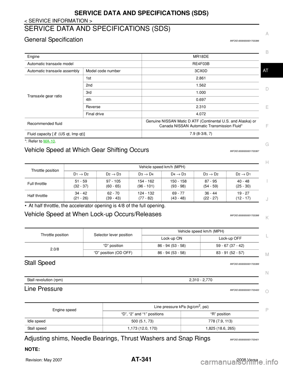
General SpecificationINFOID:0000000001703396
*: Refer to MA-10.
Vehicle Speed at Which Gear Shifting OccursINFOID:0000000001703397
• At half throttle, the accelerator opening is 4/8 of the full opening.
Vehicle Speed at When Lock-up Occurs/ReleasesINFOID:0000000001703398
Stall SpeedINFOID:0000000001703399
Line PressureINFOID:0000000001703400
Adjusting shims, Needle Bearings, Thrust Washers and Snap RingsINFOID:0000000001703401
NOTE:
EngineMR18DE
Automatic transaxle model RE4F03B
Automatic transaxle assembly Model code number 3CX0D
Transaxle gear ratio1st 2.861
2nd 1.562
3rd 1.000
4th 0.697
Reverse 2.310
Final drive 4.072
Recommended fluidGenuine NISSAN Matic D ATF (Continental U.S. and Alaska) or
Canada NISSAN Automatic Transmission Fluid*
Fluid capacity [ (US qt, Imp qt)]7.9 (8-3/8, 7)
Throttle positionVehicle speed km/h (MPH)
D1 → D2D2 → D3D3 → D4D4 → D3D3 → D2D2 → D1
Full throttle51 - 59
(32 - 37)97 - 105
(60 - 65)154 - 162
(96 - 101)150 - 158
(93 - 98)87 - 95
(54 - 59)40 - 48
(25 - 30)
Half throttle34 - 42
(21 - 26)62 - 70
(39 - 43)124 - 132
(77 - 82)69 - 77
(43 - 48)36 - 44
(22 - 27)19 - 27
(12 - 17)
Throttle position Selector lever positionVehicle speed km/h (MPH)
Lock-up ON Lock-up OFF
2.0/8“D” position 86 - 94 (53 - 58) 59 - 67 (37 - 42)
“D” position (OD OFF) 86 - 94 (53 - 58) 83 - 91 (52 - 57)
Stall revolution (rpm)2,310 - 2,770
Engine speedLine pressure kPa (kg/cm2, psi)
“D”, “2” and “1” positions “R” position
Idle speed 500 (5.1, 73) 778 (7.9, 113)
Stall speed 1,173 (12.0, 170) 1,825 (18.6, 265)
Page 510 of 2771

BL-76
< SERVICE INFORMATION >
INTELLIGENT KEY SYSTEM
System Description
INFOID:0000000001703999
• The Intelligent Key system is a system that makes it possible to lock and unlock the door locks (door lock/
unlock function), and start the engine (engine start function) by carrying around the Intelligent Key (without
some key operation), which operates based on the results of electronic ID verification using two-way com-
munications between the Intelligent Key and the vehicle (Intelligent Key unit).
• Vehicles equipped with a manual transmission include a key interlock solenoid located in the steering col-
umn to prevent accidental shut-off of the ignition switch and locking of the steering wheel during driving con-
dition when the vehicle is moving.
CAUTION:
The driver should always carry the Intelligent Key
• Operation of the remote controller buttons on the Intelligent Key also provides the same functions as the
remote control entry system. (Remote keyless entry functions)
• If an action that does not meet the operating conditions of the Intelligent Key system is taken, the buzzer
goes off to inform the driver. (Warning chime functions)
• When a door lock is locked or unlocked with request switch or remote controller button operation, the hazard
lamps flash and the buzzer (outside vehicle) sounds (Hazard and buzzer reminder function).
• Even if the Intelligent Key battery is completely discharged, the door locks can be locked and unlocked and
the engine started with the mechanical key built into the Intelligent Key.
• The settings for each function can be changed with the CONSULT-III.
• If an Intelligent Key is lost, a new Intelligent Key can be registered. A maximum of 4 Intelligent Keys can be
registered.
• It has been made possible to diagnose the system and register an Intelligent Key with the CONSULT-III.
DOOR LOCK/UNLOCK FUNCTION
Only when pressing the request switch, it is possible to lock and unlock the door by carrying around the Intelli-
gent Key (without some key operation).
System Diagram
Operation Description
• When the Intelligent Key unit detects that each request switch is pressed, it starts the outside key antenna
and inside key antenna corresponding to the pressed request switch and sends the request signal to the
Intelligent Key. And then, make sure that the Intelligent Key is near door.
• If the Intelligent Key is within the outside key antenna detection area, it receives the request signal and
sends the key ID signal to the Intelligent Key unit.
• Intelligent Key unit receives the key ID signal and compares it with the registered key ID.
• If the key ID check result is OK, the Intelligent Key unit sends the door lock/unlock request signal to BCM
(Body control module) via CAN communication line.
• Intelligent Key unit sends the door lock/unlock signal and sounds Intelligent Key warning buzzer (lock: 2
times, unlock: 1 time) at the same time.
• When BCM receives the door lock/unlock signal, it operates door lock actuator and flashes the hazard warn-
ing lamp (lock: 2 times, unlock: 1 time) at the same time as reminder.
Operation Condition
If the following conditions are not satisfied, door lock/unlock operations are not performed even if the request
switch is operated.
LIIA2926E
Page 532 of 2771

BL-98
< SERVICE INFORMATION >
INTELLIGENT KEY SYSTEM
*1: With continuously variable transmission (CVT).
*2: With manual transmission (M/T).
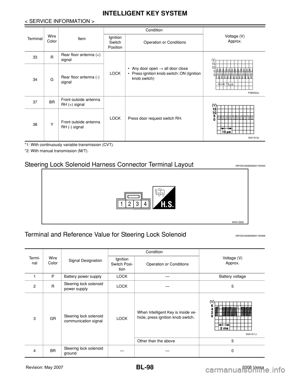
Steering Lock Solenoid Harness Connector Terminal LayoutINFOID:0000000001704005
Terminal and Reference Value for Steering Lock SolenoidINFOID:0000000001704006
33 RRear floor antenna (+)
signal
LOCK• Any door open → all door close
• Press ignition knob switch: ON (Ignition
knob switch)
34 GRear floor antenna (-)
signal
37 BRFront outside antenna
RH (+) signal
LOCK Press door request switch RH.
38 YFront outside antenna
RH (-) signal Te r m i n a lWire
ColorItemCondition
Voltage (V)
Approx. Ignition
Switch
PositionOperation or Conditions
PIIB5502J
SIIA1910J
WIIA1283E
Te r m i -
nalWire
ColorSignal DesignationCondition
Voltage (V)
Approx. Ignition
Switch Posi-
tionOperation or Conditions
1 P Battery power supply LOCK — Battery voltage
2RSteering lock solenoid
power supplyLOCK — 5
3GRSteering lock solenoid
communication signalLOCKWhen Intelligent Key is inside ve-
hicle, press ignition knob switch.
Other than the above 5
4BRSteering lock solenoid
ground—— 0
SIIA1911J
Page 802 of 2771

CL-1
TRANSMISSION/TRANSAXLE
D
E
F
G
H
I
J
K
L
M
SECTION CL
A
B
CL
N
O
P
CONTENTS
CLUTCH
SERVICE INFORMATION ............................2
PRECAUTIONS ...................................................2
Precaution for Supplemental Restraint System
(SRS) "AIR BAG" and "SEAT BELT PRE-TEN-
SIONER" ...................................................................
2
Precaution for Procedure without Cowl Top Cover ......2
Service Notice or Precaution .....................................2
PREPARATION ...................................................3
Special Service Tool .................................................3
Commercial Service Tool ..........................................3
NOISE, VIBRATION AND HARSHNESS
(NVH) TROUBLESHOOTING .............................
4
NVH Troubleshooting Chart ......................................4
CLUTCH PEDAL .................................................5
On-vehicle Inspection and Adjustment ......................5
Removal and Installation ...........................................6
CLUTCH FLUID ...................................................8
Air Bleeding Procedure .............................................8
CLUTCH MASTER CYLINDER .........................9
Removal and Installation ..........................................9
CSC (CONCENTRIC SLAVE CYLINDER) .......11
Removal and Installation .........................................11
CLUTCH PIPING ...............................................12
Removal and Installation .........................................12
CLUTCH DISC, CLUTCH COVER AND FLY-
WHEEL ..............................................................
13
Removal and Installation .........................................13
SERVICE DATA AND SPECIFICATIONS
(SDS) .................................................................
16
Clutch Control System .............................................16
Clutch Pedal ............................................................16
Clutch Disc ..............................................................16
Clutch Cover ............................................................16
Page 840 of 2771

CVT-1
TRANSMISSION/TRANSAXLE
D
E
F
G
H
I
J
K
L
M
SECTION CVT
A
B
CVT
N
O
P
CONTENTS
CVT
SERVICE INFORMATION ............................5
INDEX FOR DTC .................................................5
Alphabetical Index .....................................................5
DTC No. Index ..........................................................5
PRECAUTIONS ...................................................7
Precaution for Supplemental Restraint System
(SRS) "AIR BAG" and "SEAT BELT PRE-TEN-
SIONER" ...................................................................
7
Precaution Necessary for Steering Wheel Rota-
tion After Battery Disconnect .....................................
7
Precaution for On Board Diagnosis (OBD) System
of CVT and Engine ....................................................
7
Service After Replacing TCM and Transaxle As-
sembly .......................................................................
8
Removal and Installation Procedure for CVT Unit
Connector ..................................................................
9
Precaution ...............................................................10
Service Notice or Precaution ...................................11
PREPARATION ..................................................12
Special Service Tool ...............................................12
Commercial Service Tool ........................................12
CVT FLUID .........................................................13
Checking CVT Fluid ................................................13
Changing CVT Fluid ................................................14
CVT Fluid Cooler Cleaning .....................................14
CVT SYSTEM .....................................................18
Cross-Sectional View - RE0F08A ...........................18
Control System ........................................................19
Hydraulic Control System ........................................20
TCM Function ..........................................................20
CAN Communication ...............................................21
Input/Output Signal of TCM .....................................22
Line Pressure and Secondary Pressure Control .....22
Shift Control ............................................................23
Lock-up and Select Control .....................................24
Control Valve ...........................................................25
ON BOARD DIAGNOSTIC (OBD) SYSTEM ....26
Introduction ..............................................................26
OBD-II Function for CVT System ............................26
One or Two Trip Detection Logic of OBD-II .............26
OBD-II Diagnostic Trouble Code (DTC) ..................26
Malfunction Indicator Lamp (MIL) ............................27
TROUBLE DIAGNOSIS ....................................29
DTC Inspection Priority Chart ..................................29
Fail-Safe ..................................................................29
How to Perform Trouble Diagnosis for Quick and
Accurate Repair .......................................................
30
CVT Electrical Parts Location ..................................35
Circuit Diagram ........................................................36
Inspections before Trouble Diagnosis .....................36
Road Test ................................................................40
Check before Engine Is Started ...............................41
Check at Idle ............................................................41
Cruise Test ..............................................................43
Vehicle Speed When Shifting Gears .......................45
TCM Terminal and Reference Value .......................45
CONSULT-III Function (TRANSMISSION) ..............47
Diagnosis Procedure without CONSULT-III ............55
DTC U1000 CAN COMMUNICATION LINE .....56
Description ...............................................................56
On Board Diagnosis Logic .......................................56
Possible Cause ........................................................56
DTC Confirmation Procedure ..................................56
Wiring Diagram - CVT - CAN ...................................57
Diagnosis Procedure ...............................................58
DTC U1010 TRANSMISSION CONTROL
MODULE (CAN) ................................................
59
Description ...............................................................59
On Board Diagnosis Logic .......................................59
Possible Cause ........................................................59
DTC Confirmation Procedure ..................................59
Diagnosis Procedure ...............................................59
DTC P0615 START SIGNAL CIRCUIT .............60
Page 842 of 2771

CVT-3
D
E
F
G
H
I
J
K
L
MA
B
CVT
N
O
P N CONSULT-III Reference Value in Data Monitor
Mode .....................................................................
100
On Board Diagnosis Logic ....................................100
Possible Cause .....................................................100
DTC Confirmation Procedure ................................100
Diagnosis Procedure .............................................100
DTC P0776 PRESSURE CONTROL SOLE-
NOID B PERFORMANCE (SEC PRESSURE
SOLENOID VALVE) .........................................
102
Description ............................................................102
CONSULT-III Reference Value in Data Monitor
Mode .....................................................................
102
On Board Diagnosis Logic ....................................102
Possible Cause .....................................................102
DTC Confirmation Procedure ................................102
Diagnosis Procedure .............................................102
DTC P0778 PRESSURE CONTROL SOLE-
NOID B ELECTRICAL (SEC PRESSURE SO-
LENOID VALVE) ..............................................
104
Description ............................................................104
CONSULT-III Reference Value in Data Monitor
Mode .....................................................................
104
On Board Diagnosis Logic ....................................104
Possible Cause .....................................................104
DTC Confirmation Procedure ................................104
Wiring Diagram - CVT - SECPSV .........................105
Diagnosis Procedure .............................................106
Component Inspection ..........................................107
DTC P0840 TRANSMISSION FLUID PRES-
SURE SENSOR A CIRCUIT (SEC PRES-
SURE SENSOR) ...............................................
109
Description ............................................................109
CONSULT-III Reference Value in Data Monitor
Mode .....................................................................
109
On Board Diagnosis Logic ....................................109
Possible Cause .....................................................109
DTC Confirmation Procedure ................................109
Wiring Diagram - CVT - SECPS ............................110
Diagnosis Procedure .............................................111
DTC P0841 PRESSURE SENSOR FUNC-
TION .................................................................
113
Description ............................................................113
CONSULT-III Reference Value in Data Monitor
Mode .....................................................................
113
On Board Diagnosis Logic ....................................113
Possible Cause .....................................................113
DTC Confirmation Procedure ................................113
Diagnosis Procedure .............................................113
DTC P0845 TRANSMISSION FLUID PRES-
SURE SENSOR B CIRCUIT (PRI PRESSURE
SENSOR) ..........................................................
115
Description ............................................................115
CONSULT-III Reference Value in Data Monitor
Mode .....................................................................
115
On Board Diagnosis Logic .....................................115
Possible Cause ......................................................115
DTC Confirmation Procedure ................................115
Wiring Diagram - CVT - PRIPS .............................116
Diagnosis Procedure .............................................117
DTC P0868 SECONDARY PRESSURE
DOWN .............................................................
119
Description .............................................................119
CONSULT-III Reference Value in Data Monitor
Mode ......................................................................
119
On Board Diagnosis Logic .....................................119
Possible Cause ......................................................119
DTC Confirmation Procedure ................................119
Diagnosis Procedure .............................................119
DTC P1701 TRANSMISSION CONTROL
MODULE (POWER SUPPLY) .........................
121
Description .............................................................121
On Board Diagnosis Logic .....................................121
Possible Cause ......................................................121
DTC Confirmation Procedure ................................121
Wiring Diagram - CVT - POWER ...........................122
Diagnosis Procedure .............................................123
DTC P1705 THROTTLE POSITION SENSOR .125
Description .............................................................125
CONSULT-III Reference Value in Data Monitor
Mode ......................................................................
125
On Board Diagnosis Logic .....................................125
Possible Cause ......................................................125
DTC Confirmation Procedure ................................125
Diagnosis Procedure .............................................125
DTC P1722 ESTM VEHICLE SPEED SIGNAL .127
Description .............................................................127
CONSULT-III Reference Value in Data Monitor
Mode ......................................................................
127
On Board Diagnosis Logic .....................................127
Possible Cause ......................................................127
DTC Confirmation Procedure ................................127
Diagnosis Procedure .............................................127
DTC P1723 CVT SPEED SENSOR FUNC-
TION ................................................................
129
Description .............................................................129
On Board Diagnosis Logic .....................................129
Possible Cause ......................................................129
DTC Confirmation Procedure ................................129
Diagnosis Procedure .............................................129
DTC P1726 ELECTRIC THROTTLE CON-
TROL SYSTEM ...............................................
131
Description .............................................................131
On Board Diagnosis Logic .....................................131
Possible Cause ......................................................131
DTC Confirmation Procedure ................................131
Diagnosis Procedure .............................................131
Page 843 of 2771

CVT-4
DTC P1740 LOCK-UP SELECT SOLENOID
VALVE CIRCUIT ..............................................
132
Description .............................................................132
CONSULT-III Reference Value in Data Monitor
Mode ......................................................................
132
On Board Diagnosis Logic .....................................132
Possible Cause ......................................................132
DTC Confirmation Procedure ................................132
Wiring Diagram - CVT - L/USSV ............................133
Diagnosis Procedure .............................................134
Component Inspection ...........................................135
DTC P1745 LINE PRESSURE CONTROL ......136
Description .............................................................136
On Board Diagnosis Logic .....................................136
Possible Cause ......................................................136
DTC Confirmation Procedure ................................136
Diagnosis Procedure .............................................136
DTC P1777 STEP MOTOR - CIRCUIT ............137
Description .............................................................137
CONSULT-III Reference Value in Data Monitor
Mode ......................................................................
137
On Board Diagnosis Logic .....................................137
Possible Cause ......................................................137
DTC Confirmation Procedure ................................137
Wiring Diagram - CVT - STM .................................138
Diagnosis Procedure .............................................139
Component Inspection ...........................................140
DTC P1778 STEP MOTOR - FUNCTION ........141
Description .............................................................141
CONSULT-III Reference Value in Data Monitor
Mode ......................................................................
141
On Board Diagnosis Logic .....................................141
Possible Cause ......................................................141
DTC Confirmation Procedure ................................141
Diagnosis Procedure .............................................142
OVERDRIVE CONTROL SWITCH ..................143
Description .............................................................143
CONSULT-III Reference Value in Data Monitor
Mode ......................................................................
143
Wiring Diagram - CVT - ODSW .............................144
Diagnosis Procedure .............................................144
Component Inspection ...........................................146
SHIFT POSITION INDICATOR CIRCUIT ........148
Description .............................................................148
CONSULT-III Reference Value in Data Monitor
Mode ......................................................................
148
Diagnosis Procedure .............................................148
TROUBLE DIAGNOSIS FOR SYMPTOMS .....149
Wiring Diagram - CVT - NONDTC .........................149
O/D OFF Indicator Lamp Does Not Come On ......151
Engine Cannot Be Started in "P" and "N" Position .153
In "P" Position, Vehicle Moves Forward or Back-
ward When Pushed ...............................................
153
In "N" Position, Vehicle Moves ..............................154
Large Shock "N" → "R" Position ...........................154
Vehicle Does Not Creep Backward in "R" Position .155
Vehicle Does Not Creep Forward in "D" or "L" Po-
sition ......................................................................
156
Vehicle Speed Does Not Change in "L" Position ..157
Vehicle Speed Does Not Change in overdrive-off
mode .....................................................................
158
Vehicle Speed Does Not Change in "D" Position .159
Vehicle Does Not Decelerate by Engine Brake ....159
TRANSMISSION CONTROL MODULE ...........161
Removal and Installation .......................................161
CVT SHIFT LOCK SYSTEM .............................162
Description ............................................................162
Shift Lock System Electrical Parts Location ..........162
Wiring Diagram - CVT - SHIFT .............................163
Diagnosis Procedure .............................................163
SHIFT CONTROL SYSTEM .............................167
Removal and Installation .......................................167
Control Device Disassembly and Assembly .........170
Selector Lever Knob Removal and Installation .....170
Adjustment of CVT Position ..................................171
Checking of CVT Position .....................................171
KEY INTERLOCK CABLE ...............................173
Removal and Installation .......................................173
AIR BREATHER HOSE ....................................176
Removal and Installation .......................................176
DIFFERENTIAL SIDE OIL SEAL .....................177
Removal and Installation .......................................177
TRANSAXLE ASSEMBLY ...............................178
Removal and Installation .......................................178
SERVICE DATA AND SPECIFICATIONS
(SDS) ................................................................
181
General Specification ............................................181
Vehicle Speed When Shifting Gears .....................181
Stall Speed ............................................................181
Line Pressure ........................................................181
Solenoid Valves ....................................................182
CVT Fluid Temperature Sensor ............................182
Primary Speed Sensor ..........................................182
Secondary Speed Sensor .....................................182
Removal and Installation .......................................182
Page 844 of 2771

INDEX FOR DTC
CVT-5
< SERVICE INFORMATION >
D
E
F
G
H
I
J
K
L
MA
B
CVT
N
O
P
SERVICE INFORMATION
INDEX FOR DTC
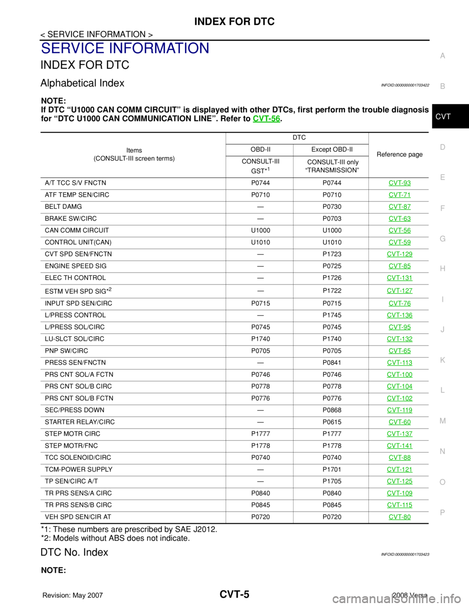
Alphabetical IndexINFOID:0000000001703422
NOTE:
If DTC “U1000 CAN COMM CIRCUIT” is displayed with other DTCs, first perform the trouble diagnosis
for “DTC U1000 CAN COMMUNICATION LINE”. Refer to CVT-56
.
*1: These numbers are prescribed by SAE J2012.
*2: Models without ABS does not indicate.
DTC No. IndexINFOID:0000000001703423
NOTE:
Items
(CONSULT-III screen terms) DTC
Reference page OBD-II Except OBD-II
CONSULT-III
GST*
1 CONSULT-III only
“TRANSMISSION”
A/T TCC S/V FNCTN P0744 P0744 CVT-93
ATF TEMP SEN/CIRC P0710 P0710CVT-71
BELT DAMG — P0730CVT-87
BRAKE SW/CIRC — P0703CVT-63
CAN COMM CIRCUIT U1000 U1000CVT-56
CONTROL UNIT(CAN) U1010 U1010CVT-59
CVT SPD SEN/FNCTN — P1723CVT-129
ENGINE SPEED SIG — P0725CVT-85
ELEC TH CONTROL — P1726CVT-131
ESTM VEH SPD SIG*2— P1722CVT-127
INPUT SPD SEN/CIRC P0715 P0715CVT-76
L/PRESS CONTROL — P1745CVT-136
L/PRESS SOL/CIRC P0745 P0745CVT-95
LU-SLCT SOL/CIRC P1740 P1740CVT-132
PNP SW/CIRC P0705 P0705CVT-65
PRESS SEN/FNCTN — P0841CVT-113
PRS CNT SOL/A FCTN P0746 P0746CVT-100
PRS CNT SOL/B CIRC P0778 P0778CVT-104
PRS CNT SOL/B FCTN P0776 P0776CVT-102
SEC/PRESS DOWN — P0868CVT-119
STARTER RELAY/CIRC — P0615CVT-60
STEP MOTR CIRC P1777 P1777CVT-137
STEP MOTR/FNC P1778 P1778CVT-141
TCC SOLENOID/CIRC P0740 P0740CVT-88
TCM-POWER SUPPLY — P1701CVT-121
TP SEN/CIRC A/T — P1705CVT-125
TR PRS SENS/A CIRC P0840 P0840CVT-109
TR PRS SENS/B CIRC P0845 P0845CVT-115
VEH SPD SEN/CIR AT P0720 P0720CVT-80