2008 NISSAN TIIDA phone
[x] Cancel search: phonePage 413 of 2771
AV-54
< SERVICE INFORMATION >
TELEPHONE
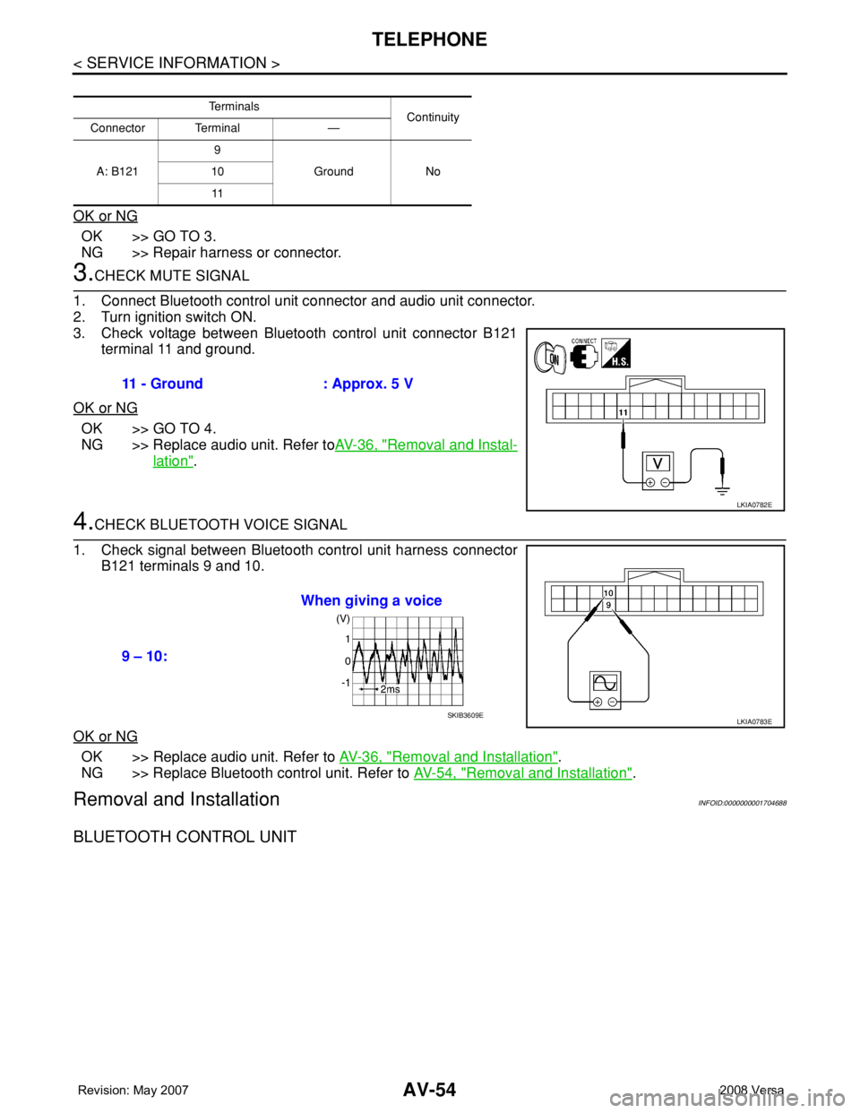
OK or NG
OK >> GO TO 3.
NG >> Repair harness or connector.
3.CHECK MUTE SIGNAL
1. Connect Bluetooth control unit connector and audio unit connector.
2. Turn ignition switch ON.
3. Check voltage between Bluetooth control unit connector B121
terminal 11 and ground.
OK or NG
OK >> GO TO 4.
NG >> Replace audio unit. Refer toAV-36, "
Removal and Instal-
lation".
4.CHECK BLUETOOTH VOICE SIGNAL
1. Check signal between Bluetooth control unit harness connector
B121 terminals 9 and 10.
OK or NG
OK >> Replace audio unit. Refer to AV-36, "Removal and Installation".
NG >> Replace Bluetooth control unit. Refer to AV-54, "
Removal and Installation".
Removal and InstallationINFOID:0000000001704688
BLUETOOTH CONTROL UNIT
Te r m i n a l s
Continuity
Connector Terminal —
A: B1219
Ground No 10
11
11 - Ground : Approx. 5 V
LKIA0782E
9 – 10:When giving a voice
LKIA0783ESKIB3609E
Page 414 of 2771
TELEPHONE
AV-55
< SERVICE INFORMATION >
C
D
E
F
G
H
I
J
L
MA
B
AV
N
O
P
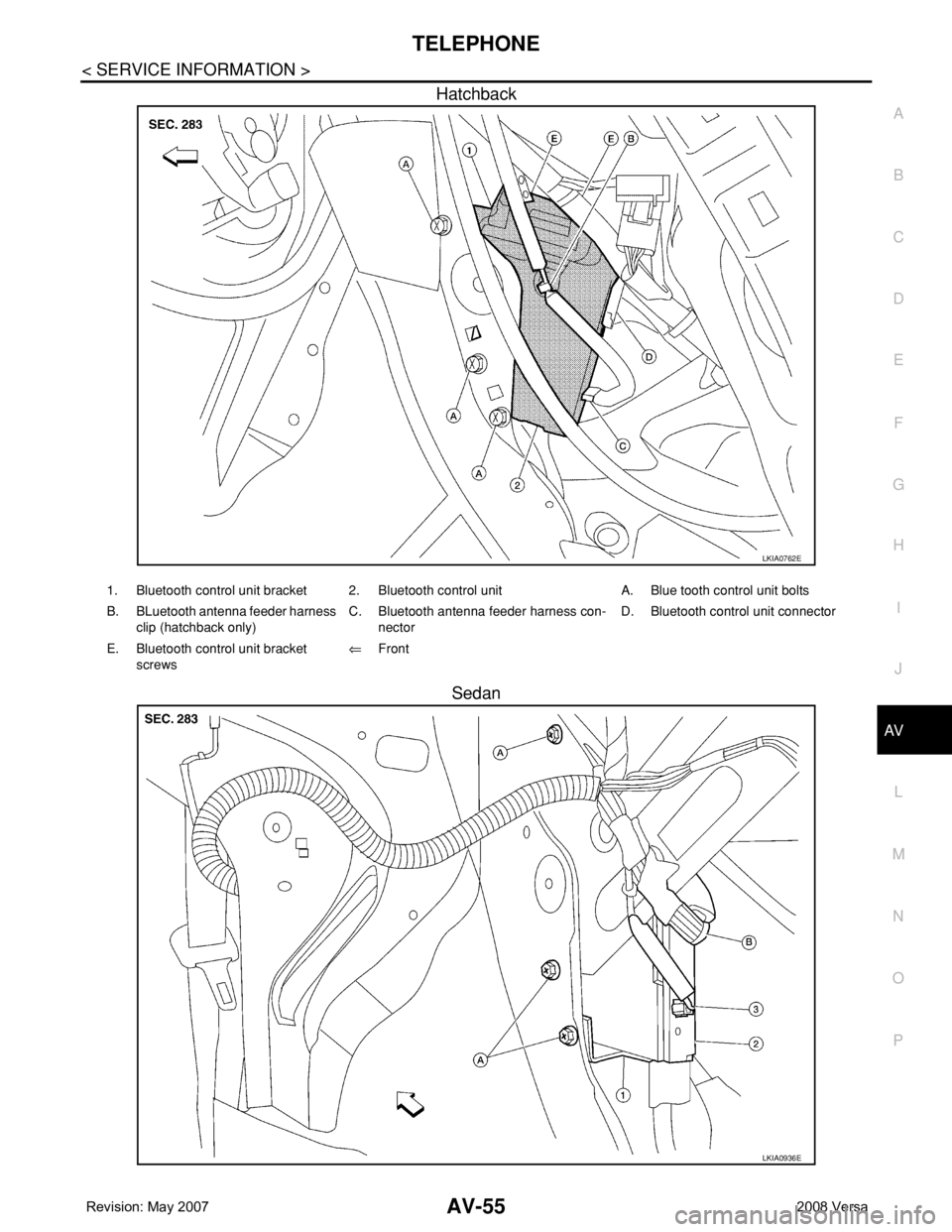
Hatchback
Sedan
LKIA0762E
1. Bluetooth control unit bracket 2. Bluetooth control unit A. Blue tooth control unit bolts
B. BLuetooth antenna feeder harness
clip (hatchback only)C. Bluetooth antenna feeder harness con-
nectorD. Bluetooth control unit connector
E. Bluetooth control unit bracket
screws⇐Front
LKIA0936E
Page 415 of 2771
AV-56
< SERVICE INFORMATION >
TELEPHONE
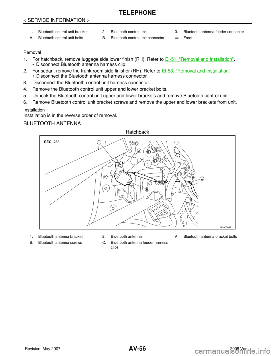
Removal
1. For hatchback, remove luggage side lower finish (RH). Refer to EI-51, "Removal and Installation".
• Disconnect Bluetooth antenna harness clip.
2. For sedan, remove the trunk room side finisher (RH). Refer to EI-53, "
Removal and Installation".
• Disconnect the Bluetooth antenna harness connector.
3. Disconnect the Bluetooth control unit harness connector.
4. Remove the Bluetooth control unit upper and lower bracket bolts.
5. Unhook the Bluetooth control unit upper and lower brackets and remove Bluetooth control unit.
6. Remove Bluetooth control unit bracket screws and remove the upper and lower brackets from unit.
Installation
Installation is in the reverse order of removal.
BLUETOOTH ANTENNA
Hatchback
1. Bluetooth control unit bracket 2. Bluetooth control unit 3. Bluetooth antenna feeder connector
A. Bluetooth control unit bolts B. Bluetooth control unit connector⇐Front
LKIA0763E
1. Bluetooth antenna bracket 2. Bluetooth antenna A. Bluetooth antenna bracket bolts
B. Bluetooth antenna screws C. Bluetooth antenna feeder harness
clips
Page 416 of 2771
TELEPHONE
AV-57
< SERVICE INFORMATION >
C
D
E
F
G
H
I
J
L
MA
B
AV
N
O
P
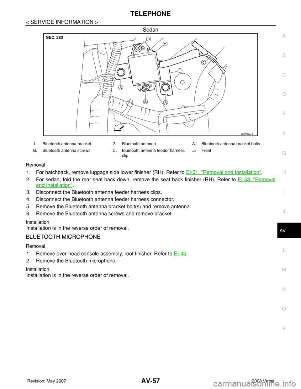
Sedan
Removal
1. For hatchback, remove luggage side lower finisher (RH). Refer to EI-51, "Removal and Installation".
2. For sedan, fold the rear seat back down, remove the seat back finisher (RH). Refer to EI-53, "
Removal
and Installation".
3. Disconnect the Bluetooth antenna feeder harness clips.
4. Disconnect the Bluetooth antenna feeder harness connector.
5. Remove the Bluetooth antenna bracket bolt(s) and remove antenna.
6. Remove the Bluetooth antenna screws and remove bracket.
Installation
Installation is in the reverse order of removal.
BLUETOOTH MICROPHONE
Removal
1. Remove over-head console assembly, roof finisher. Refer to EI-45.
2. Remove the Bluetooth microphone.
Installation
Installation is in the reverse order of removal.
LKIA0937E
1. Bluetooth antenna bracket 2. Bluetooth antenna A. Bluetooth antenna bracket bolts
B. Bluetooth antenna screws C. Bluetooth antenna feeder harness
clip⇒Front
Page 1093 of 2771
PRECAUTIONS
EC-19
< SERVICE INFORMATION >
C
D
E
F
G
H
I
J
K
L
MA
EC
N
P O
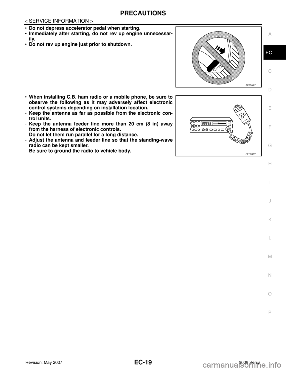
•Do not depress accelerator pedal when starting.
•Immediately after starting, do not rev up engine unnecessar-
ily.
•Do not rev up engine just prior to shutdown.
•When installing C.B. ham radio or a mobile phone, be sure to
observe the following as it may adversely affect electronic
control systems depending on installation location.
-Keep the antenna as far as possible from the electronic con-
trol units.
-Keep the antenna feeder line more than 20 cm (8 in) away
from the harness of electronic controls.
Do not let them run parallel for a long distance.
-Adjust the antenna and feeder line so that the standing-wave
radio can be kept smaller.
-Be sure to ground the radio to vehicle body.
SEF709Y
SEF708Y
Page 2242 of 2771

ILLUMINATION
LT-105
< SERVICE INFORMATION >
C
D
E
F
G
H
I
J
L
MA
B
LT
N
O
P
ILLUMINATION
System DescriptionINFOID:0000000001704480
The control of the illumination lamps operation is dependent upon the position of the lighting switch. When the
lighting switch is placed in the 1ST or 2ND position, the BCM (body control module) receives input signal
requesting the illumination lamps to illuminate. This input signal is communicated to IPDM E/R (intelligent
power distribution module engine room) across CAN communication lines. CPU (central processing unit)
located in the IPDM E/R controls the tail lamp relay coil. This relay, when energized, directs power to the illu-
mination lamps, which then illuminate.
Power is supplied at all times
• to ignition relay, located in IPDM E/R,
• to tail lamp relay, located in IPDM E/R,
• through 15A fuse (No. 52, located in IPDM E/R) and
• through 20A fuse (No. 53, located in IPDM E/R)
• to CPU located in IPDM E/R,
• through 40A fusible link (letter g , located in fuse and fusible link box)
• to BCM terminal 70, and
• through 10A fuse [No. 8, located in fuse block (J/B)]
• to BCM terminal 57.
With the ignition switch in the ON or START position, power is supplied
• to ignition relay, located in IPDM E/R, and
• through 10A fuse [No. 6, located in fuse block (J/B)]
• to BCM terminal 38.
With the ignition switch in the ACC or ON position, power is supplied
• through 10A fuse [No. 20, located in fuse block (J/B)]
• to BCM terminal 11.
Ground is supplied
• to BCM terminal 67
• through grounds M57 and M61, and
• to IPDM E/R terminals 39 and 59
• through grounds E15 and E24.
ILLUMINATION OPERATION BY LIGHTING SWITCH
With the lighting switch in the 1ST or 2ND position, BCM receives input signal requesting the illumination
lamps to illuminate. This input signal is communicated to IPDM E/R across CAN communication lines. CPU
located in the IPDM E/R controls the tail lamp relay coil, which, when energized, directs power
• through 10A fuse (No. 37, located in IPDM E/R)
• through IPDM E/R terminal 29
• to microphone terminal 3 (with Bluetooth)
• to illumination control switch terminal 1
• to glove box lamp terminal 1 (with glovebox lamp)
• to audio unit terminal 9
• to front air control terminal 5
• to A/T device terminal 3 (with 4-speed A/T)
• to CVT device terminal 3 (with CVT)
• to hazard switch terminal 3
• to combination meter terminal 12
• to door mirror remote control switch terminal 16, and
Ground is supplied
• to microphone terminal 2 (with Bluetooth)
• to glove box lamp terminal 2 (with glove box lamp), and
• to illumination control switch terminal 3
• through grounds M57 and M61.
The illumination control switch controls illumination intensity by varying the ground to the following
• through illumination control switch terminal 2
• to audio unit terminal 8
• to front air control terminal 6
• to A/T device terminal 4 (with 4-speed A/T)
• to CVT device terminal 3 (with CVT)
• to hazard switch terminal 4
Page 2486 of 2771
HARNESS
PG-53
< SERVICE INFORMATION >
C
D
E
F
G
H
I
J
L
MA
B
PG
N
O
P
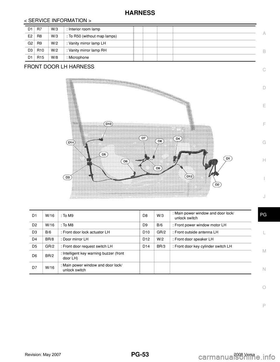
FRONT DOOR LH HARNESS
D1 R7 W/3 : Interior room lamp
E2 R8 W/3 : To R50 (without map lamps)
G2 R9 W/2 : Vanity mirror lamp LH
D3 R10 W/2 : Vanity mirror lamp RH
D1 R15 W/8 : Microphone
D1 W/16 : To M9 D8 W/3: Main power window and door lock/
unlock switch
D2 W/16 : To M8 D9 B/6 : Front power window motor LH
D3 B/6 : Front door lock actuator LH D10 GR/2 : Front outside antenna LH
D4 BR/8 : Door mirror LH D12 W/2 : Front door speaker LH
D5 GR/2 : Front door request switch LH D14 BR/3 : Front door key cylinder switch LH
D6 BR/2: Intelligent key warning buzzer (front
door LH)
D7 W/16: Main power window and door lock/
unlock switch
Page 2492 of 2771

HARNESS
PG-59
< SERVICE INFORMATION >
C
D
E
F
G
H
I
J
L
MA
B
PG
N
O
P
ETC2 EC Throttle Control Motor Relay
ETC3 EC Throttle Control Motor
F/FOG LT Front Fog Lamp
F/PUMP EC Fuel Pump
FTS AT A/T Fluid Temperature Sensor
FTS CVT CVT Fluid Temperature Sensor Circuit
FTTS EC Fuel Tank Temperature Sensor
FUEL EC Fuel Ignition System Function
HEATER MTC Heater System
H/LAMP LT Headlamp
H/PHON AV Hands Free Telephone
HORN WW Horn
HO2S2 EC Heated Oxygen Sensor 2
HO2S2H EC Heated Oxygen Sensor 2 Heater
IATS EC Intake Air Temperature Sensor
IGNSYS EC Ignition System
I/KEY BL Intelligent Key System
ILL LT Illumination
INJECT EC Injector
INT/L LT Room/Map, Vanity and Luggage Lamps
IVC EC Intake Valve Timing Control Solenoid Valve
KEYLES BL Remote Keyless Entry System
KS EC Knock Sensor
LPSV AT Line Pressure Solenoid Valve
LPSV CVT Line Pressure Solenoid Valve
L/USSV CVT Lock-up Select Solenoid Valve
MAFS EC Mass Air Flow Sensor
MAIN AT Main Power Supply and Ground Circuit
MAIN EC Main Power Supply and Ground Circuit
METER DI Speedometer, Tachometer, Temp. and Fuel Gauges
MIL/DL EC Malfunction Indicator Lamp
MIRROR GW Door Mirror
NATS BL Nissan Anti-Theft System
NONDTC AT Non-detectable Item
NONDTC CVT Non-detectable Item
ODSW CVT Overdrive Control Switch
OVRCSV AT Over Run Clutch Solenoid Valve
P/SCKT WW Power Socket
PGC/V EC EVAP Canister Purge Volume Control Solenoid Valve
PHASE EC Camshaft Position Sensor (PHASE)
PNP/SW AT Park/Neutral Position Switch
PNP/SW CVT Park/Neutral Position Switch
PNP/SW EC Park/Neutral Position Switch
POS EC Crankshaft Position Sensor (POS)
POWER CVT Transmission Control Module (Power Supply)
PRE/SE EC EVAP Control System Pressure Sensor
PRIPS CVT Primary Pressure Sensor
PRSCVT CVT Primary Speed Sensor CVT (Revolution Sensor)
PT/SEN AT Powertrain Revolution Sensor
RP/SEN EC Refrigerant Pressure Sensor
SECPS CVT Secondary Pressure Sensor
SECPSV CVT Secondary Speed Sensor CVT (Revolution Sensor)