2008 NISSAN TIIDA engine mount
[x] Cancel search: engine mountPage 853 of 2771
CVT-14
< SERVICE INFORMATION >
CVT FLUID
FLUID CONDITION CHECK
Changing CVT FluidINFOID:0000000001703434
1. Warm up CVT fluid by driving the vehicle for 10 minutes.
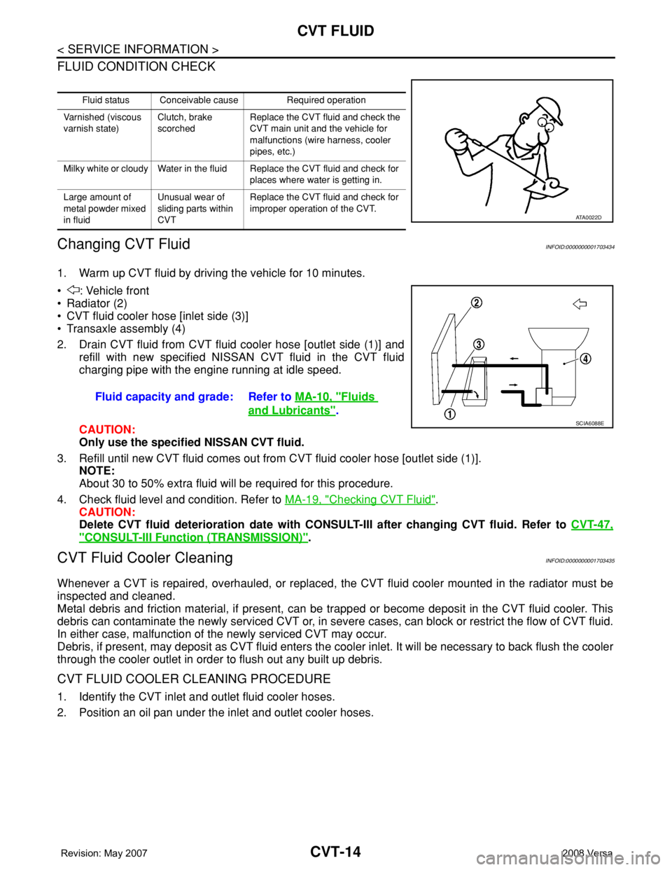
• : Vehicle front
• Radiator (2)
• CVT fluid cooler hose [inlet side (3)]
• Transaxle assembly (4)
2. Drain CVT fluid from CVT fluid cooler hose [outlet side (1)] and
refill with new specified NISSAN CVT fluid in the CVT fluid
charging pipe with the engine running at idle speed.
CAUTION:
Only use the specified NISSAN CVT fluid.
3. Refill until new CVT fluid comes out from CVT fluid cooler hose [outlet side (1)].
NOTE:
About 30 to 50% extra fluid will be required for this procedure.
4. Check fluid level and condition. Refer to MA-19, "
Checking CVT Fluid".
CAUTION:
Delete CVT fluid deterioration date with CONSULT-III after changing CVT fluid. Refer to CVT-47,
"CONSULT-III Function (TRANSMISSION)".
CVT Fluid Cooler CleaningINFOID:0000000001703435
Whenever a CVT is repaired, overhauled, or replaced, the CVT fluid cooler mounted in the radiator must be
inspected and cleaned.
Metal debris and friction material, if present, can be trapped or become deposit in the CVT fluid cooler. This
debris can contaminate the newly serviced CVT or, in severe cases, can block or restrict the flow of CVT fluid.
In either case, malfunction of the newly serviced CVT may occur.
Debris, if present, may deposit as CVT fluid enters the cooler inlet. It will be necessary to back flush the cooler
through the cooler outlet in order to flush out any built up debris.
CVT FLUID COOLER CLEANING PROCEDURE
1. Identify the CVT inlet and outlet fluid cooler hoses.
2. Position an oil pan under the inlet and outlet cooler hoses.
Fluid status Conceivable cause Required operation
Varnished (viscous
varnish state)Clutch, brake
scorchedReplace the CVT fluid and check the
CVT main unit and the vehicle for
malfunctions (wire harness, cooler
pipes, etc.)
Milky white or cloudy Water in the fluid Replace the CVT fluid and check for
places where water is getting in.
Large amount of
metal powder mixed
in fluidUnusual wear of
sliding parts within
CVTReplace the CVT fluid and check for
improper operation of the CVT.
ATA0022D
Fluid capacity and grade: Refer to MA-10, "Fluids
and Lubricants".SCIA6088E
Page 871 of 2771
CVT-32
< SERVICE INFORMATION >
TROUBLE DIAGNOSIS
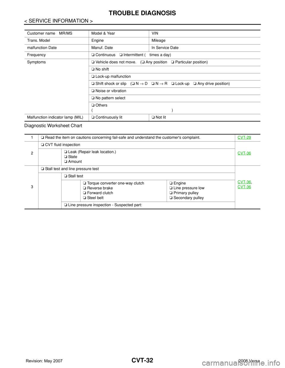
Diagnostic Worksheet Chart
Customer name MR/MS Model & Year VIN
Trans. Model Engine Mileage
malfunction Date Manuf. Date In Service Date
Frequency❏ Continuous❏ Intermittent ( times a day)
Symptoms❏ Vehicle does not move. (❏ Any position❏ Particular position)
❏ No shift
❏ Lock-up malfunction
❏ Shift shock or slip (❏ N → D❏ N → R❏ Lock-up❏ Any drive position)
❏ Noise or vibration
❏ No pattern select
❏ Others
()
Malfunction indicator lamp (MIL)❏ Continuously lit❏ Not lit
1❏ Read the item on cautions concerning fail-safe and understand the customer's complaint.CVT-29
2❏ CVT fluid inspection
CVT-36❏ Leak (Repair leak location.)
❏ Sta te
❏ Amount
3❏ Stall test and line pressure test
CVT-36
,
CVT-36
❏ Stall test
❏ Torque converter one-way clutch
❏ Reverse brake
❏ Forward clutch
❏ Steel belt❏ Engine
❏ Line pressure low
❏ Primary pulley
❏ Secondary pulley
❏ Line pressure inspection - Suspected part:
Page 876 of 2771
TROUBLE DIAGNOSIS
CVT-37
< SERVICE INFORMATION >
D
E
F
G
H
I
J
K
L
MA
B
CVT
N
O
P
• Inspect for fluid leakage and check the fluid level. Refer to MA-19, "Checking CVT Fluid" .
Fluid Condition Check
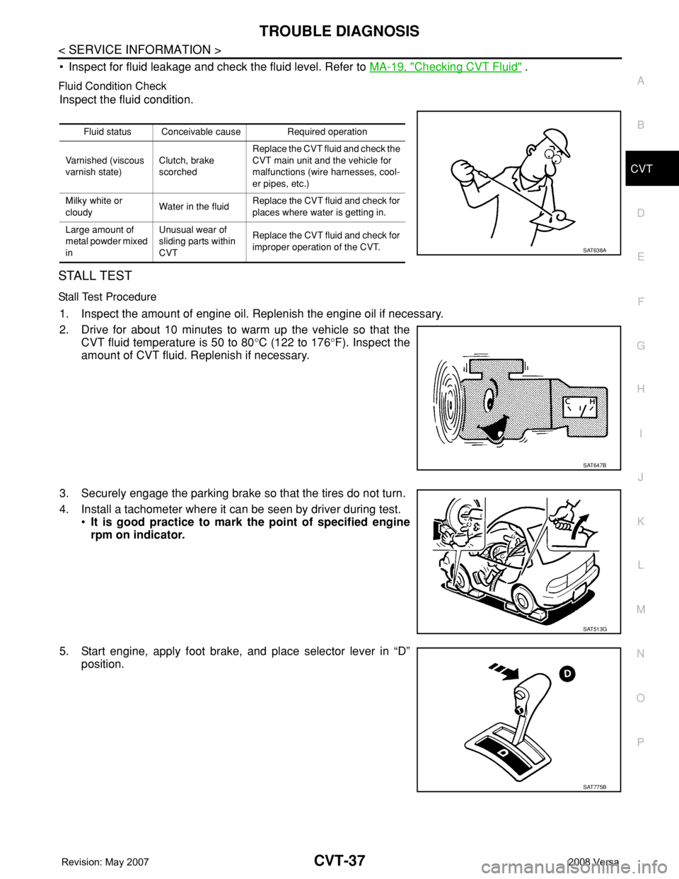
Inspect the fluid condition.
STALL TEST
Stall Test Procedure
1. Inspect the amount of engine oil. Replenish the engine oil if necessary.
2. Drive for about 10 minutes to warm up the vehicle so that the
CVT fluid temperature is 50 to 80°C (122 to 176°F). Inspect the
amount of CVT fluid. Replenish if necessary.
3. Securely engage the parking brake so that the tires do not turn.
4. Install a tachometer where it can be seen by driver during test.
•It is good practice to mark the point of specified engine
rpm on indicator.
5. Start engine, apply foot brake, and place selector lever in “D”
position.
Fluid status Conceivable cause Required operation
Varnished (viscous
varnish state)Clutch, brake
scorchedReplace the CVT fluid and check the
CVT main unit and the vehicle for
malfunctions (wire harnesses, cool-
er pipes, etc.)
Milky white or
cloudyWater in the fluidReplace the CVT fluid and check for
places where water is getting in.
Large amount of
metal powder mixed
inUnusual wear of
sliding parts within
CVTReplace the CVT fluid and check for
improper operation of the CVT.
SAT638A
SAT647B
SAT513G
SAT775B
Page 877 of 2771
CVT-38
< SERVICE INFORMATION >
TROUBLE DIAGNOSIS
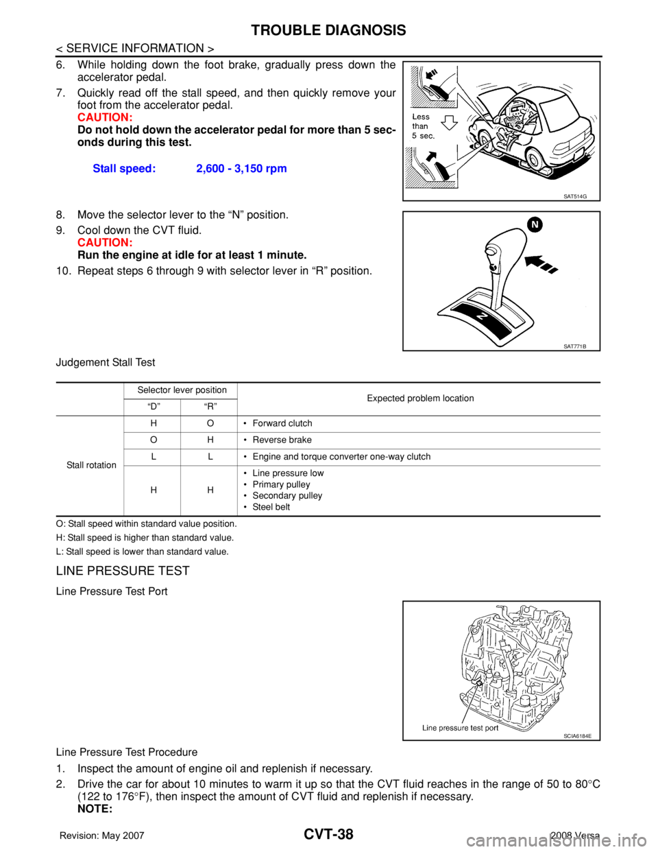
6. While holding down the foot brake, gradually press down the
accelerator pedal.
7. Quickly read off the stall speed, and then quickly remove your
foot from the accelerator pedal.
CAUTION:
Do not hold down the accelerator pedal for more than 5 sec-
onds during this test.
8. Move the selector lever to the “N” position.
9. Cool down the CVT fluid.
CAUTION:
Run the engine at idle for at least 1 minute.
10. Repeat steps 6 through 9 with selector lever in “R” position.
Judgement Stall Test
O: Stall speed within standard value position.
H: Stall speed is higher than standard value.
L: Stall speed is lower than standard value.
LINE PRESSURE TEST
Line Pressure Test Port
Line Pressure Test Procedure
1. Inspect the amount of engine oil and replenish if necessary.
2. Drive the car for about 10 minutes to warm it up so that the CVT fluid reaches in the range of 50 to 80°C
(122 to 176°F), then inspect the amount of CVT fluid and replenish if necessary.
NOTE:Stall speed: 2,600 - 3,150 rpm
SAT514G
SAT771B
Selector lever position
Expected problem location
“D” “R”
Stall rotation HO•Forward clutch
O H • Reverse brake
L L • Engine and torque converter one-way clutch
HH• Line pressure low
• Primary pulley
• Secondary pulley
• Steel belt
SCIA6184E
Page 1017 of 2771
CVT-178
< SERVICE INFORMATION >
TRANSAXLE ASSEMBLY
TRANSAXLE ASSEMBLY
Removal and InstallationINFOID:0000000001703687
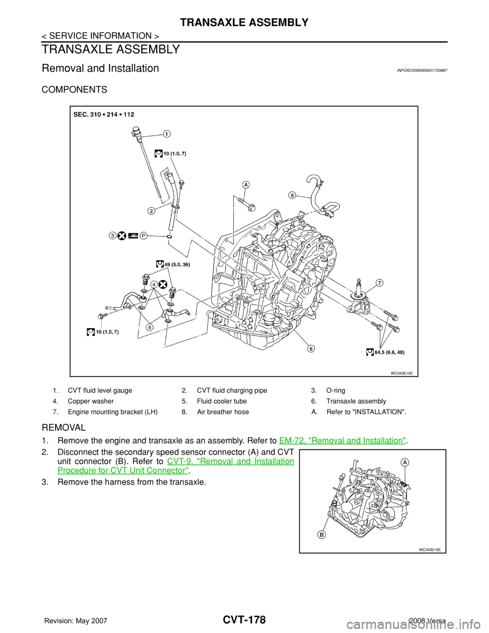
COMPONENTS
REMOVAL
1. Remove the engine and transaxle as an assembly. Refer to EM-72, "Removal and Installation".
2. Disconnect the secondary speed sensor connector (A) and CVT
unit connector (B). Refer to CVT-9, "
Removal and Installation
Procedure for CVT Unit Connector".
3. Remove the harness from the transaxle.
1. CVT fluid level gauge 2. CVT fluid charging pipe 3. O-ring
4. Copper washer 5. Fluid cooler tube 6. Transaxle assembly
7. Engine mounting bracket (LH) 8. Air breather hose A. Refer to "INSTALLATION".
WCIA0614E
WCIA0615E
Page 1018 of 2771
TRANSAXLE ASSEMBLY
CVT-179
< SERVICE INFORMATION >
D
E
F
G
H
I
J
K
L
MA
B
CVT
N
O
P
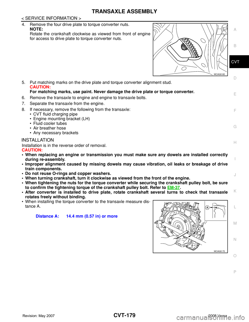
4. Remove the four drive plate to torque converter nuts.
NOTE:
Rotate the crankshaft clockwise as viewed from front of engine
for access to drive plate to torque converter nuts.
5. Put matching marks on the drive plate and torque converter alignment stud.
CAUTION:
For matching marks, use paint. Never damage the drive plate or torque converter.
6. Remove the transaxle to engine and engine to transaxle bolts.
7. Separate the transaxle from the engine.
8. If necessary, remove the following from the transaxle:
• CVT fluid charging pipe
• Engine mounting bracket (LH)
• Fluid cooler tubes
• Air breather hose
• Any necessary brackets
INSTALLATION
Installation is in the reverse order of removal.
CAUTION:
• When replacing an engine or transmission you must make sure any dowels are installed correctly
during re-assembly.
• Improper alignment caused by missing dowels may cause vibration, oil leaks or breakage of drive
train components.
• Do not reuse O-rings and copper washers.
• When turning crankshaft, turn it clockwise as viewed from the front of the engine.
• When tightening the nuts for the torque converter while securing the crankshaft pulley bolt, be sure
to confirm the tightening torque of the crankshaft pulley bolt. Refer to EM-37
.
• After converter is installed to drive plate, rotate crankshaft several turns to check that transaxle
rotates freely without binding.
• When installing the torque converter to the transaxle measure dis-
tance A.
WCIA0616E
Distance A: 14.4 mm (0.57 in) or more
WCIA0617E
Page 1097 of 2771
ENGINE CONTROL SYSTEM
EC-23
< SERVICE INFORMATION >
C
D
E
F
G
H
I
J
K
L
MA
EC
N
P O
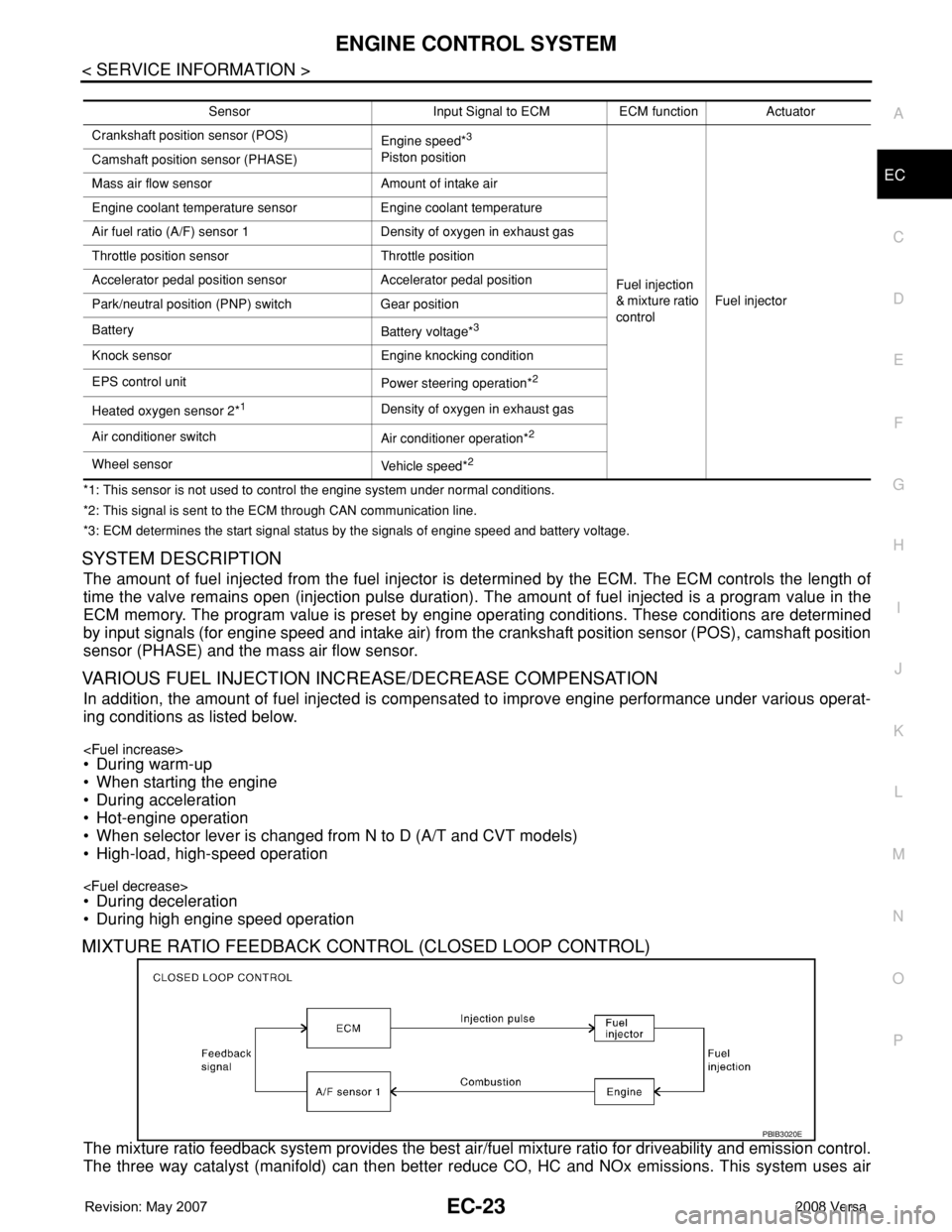
*1: This sensor is not used to control the engine system under normal conditions.
*2: This signal is sent to the ECM through CAN communication line.
*3: ECM determines the start signal status by the signals of engine speed and battery voltage.
SYSTEM DESCRIPTION
The amount of fuel injected from the fuel injector is determined by the ECM. The ECM controls the length of
time the valve remains open (injection pulse duration). The amount of fuel injected is a program value in the
ECM memory. The program value is preset by engine operating conditions. These conditions are determined
by input signals (for engine speed and intake air) from the crankshaft position sensor (POS), camshaft position
sensor (PHASE) and the mass air flow sensor.
VARIOUS FUEL INJECTION INCREASE/DECREASE COMPENSATION
In addition, the amount of fuel injected is compensated to improve engine performance under various operat-
ing conditions as listed below.
• When starting the engine
• During acceleration
• Hot-engine operation
• When selector lever is changed from N to D (A/T and CVT models)
• High-load, high-speed operation
• During deceleration
• During high engine speed operation
MIXTURE RATIO FEEDBACK CONTROL (CLOSED LOOP CONTROL)
The mixture ratio feedback system provides the best air/fuel mixture ratio for driveability and emission control.
The three way catalyst (manifold) can then better reduce CO, HC and NOx emissions. This system uses air
Sensor Input Signal to ECM ECM function Actuator
Crankshaft position sensor (POS)
Engine speed*
3
Piston position
Fuel injection
& mixture ratio
controlFuel injector Camshaft position sensor (PHASE)
Mass air flow sensor Amount of intake air
Engine coolant temperature sensor Engine coolant temperature
Air fuel ratio (A/F) sensor 1 Density of oxygen in exhaust gas
Throttle position sensor Throttle position
Accelerator pedal position sensor Accelerator pedal position
Park/neutral position (PNP) switch Gear position
Battery
Battery voltage*
3
Knock sensor Engine knocking condition
EPS control unit
Power steering operation*
2
Heated oxygen sensor 2*1Density of oxygen in exhaust gas
Air conditioner switch
Air conditioner operation*
2
Wheel sensor
Vehicle speed*2
PBIB3020E
Page 1099 of 2771
ENGINE CONTROL SYSTEM
EC-25
< SERVICE INFORMATION >
C
D
E
F
G
H
I
J
K
L
MA
EC
N
P O
FUEL SHUT-OFF
Fuel to each cylinder is cut off during deceleration, operation of the engine at excessively high speeds or oper-
ation of the vehicle at excessively high speeds.
Electronic Ignition (EI) SystemINFOID:0000000001702556
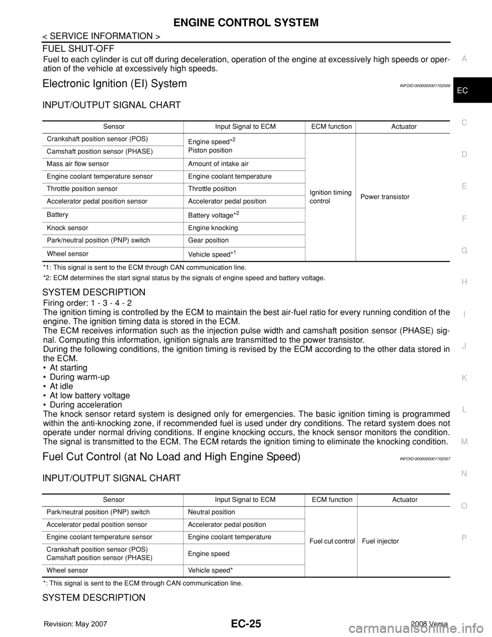
INPUT/OUTPUT SIGNAL CHART
*1: This signal is sent to the ECM through CAN communication line.
*2: ECM determines the start signal status by the signals of engine speed and battery voltage.
SYSTEM DESCRIPTION
Firing order: 1 - 3 - 4 - 2
The ignition timing is controlled by the ECM to maintain the best air-fuel ratio for every running condition of the
engine. The ignition timing data is stored in the ECM.
The ECM receives information such as the injection pulse width and camshaft position sensor (PHASE) sig-
nal. Computing this information, ignition signals are transmitted to the power transistor.
During the following conditions, the ignition timing is revised by the ECM according to the other data stored in
the ECM.
• At starting
• During warm-up
•At idle
• At low battery voltage
• During acceleration
The knock sensor retard system is designed only for emergencies. The basic ignition timing is programmed
within the anti-knocking zone, if recommended fuel is used under dry conditions. The retard system does not
operate under normal driving conditions. If engine knocking occurs, the knock sensor monitors the condition.
The signal is transmitted to the ECM. The ECM retards the ignition timing to eliminate the knocking condition.
Fuel Cut Control (at No Load and High Engine Speed)INFOID:0000000001702557
INPUT/OUTPUT SIGNAL CHART
*: This signal is sent to the ECM through CAN communication line.
SYSTEM DESCRIPTION
Sensor Input Signal to ECM ECM function Actuator
Crankshaft position sensor (POS)
Engine speed*
2
Piston position
Ignition timing
controlPower transistor Camshaft position sensor (PHASE)
Mass air flow sensor Amount of intake air
Engine coolant temperature sensor Engine coolant temperature
Throttle position sensor Throttle position
Accelerator pedal position sensor Accelerator pedal position
Battery
Battery voltage*
2
Knock sensor Engine knocking
Park/neutral position (PNP) switch Gear position
Wheel sensor
Vehicle speed*
1
Sensor Input Signal to ECM ECM function Actuator
Park/neutral position (PNP) switch Neutral position
Fuel cut control Fuel injector Accelerator pedal position sensor Accelerator pedal position
Engine coolant temperature sensor Engine coolant temperature
Crankshaft position sensor (POS)
Camshaft position sensor (PHASE)Engine speed
Wheel sensor Vehicle speed*