2008 NISSAN TIIDA P0500
[x] Cancel search: P0500Page 1079 of 2771

EC-5
C
D
E
F
G
H
I
J
K
L
M
ECA
N
O
P Component Description .........................................
338
CONSULT-II Reference Value in Data Monitor
Mode .....................................................................
338
On Board Diagnosis Logic ....................................338
DTC Confirmation Procedure ................................338
Wiring Diagram .....................................................340
Diagnosis Procedure .............................................341
Component Inspection ..........................................343
DTC P0448 EVAP CANISTER VENT CON-
TROL VALVE ...................................................
345
Component Description .........................................345
CONSULT-II Reference Value in Data Monitor
Mode .....................................................................
345
On Board Diagnosis Logic ....................................345
DTC Confirmation Procedure ................................345
Wiring Diagram .....................................................347
Diagnosis Procedure .............................................348
Component Inspection ..........................................349
DTC P0451 EVAP CONTROL SYSTEM
PRESSURE SENSOR ......................................
351
Component Description .........................................351
CONSULT-II Reference Value in Data Monitor
Mode .....................................................................
351
On Board Diagnosis Logic ....................................351
DTC Confirmation Procedure ................................351
Diagnosis Procedure .............................................352
Component Inspection ..........................................353
DTC P0452 EVAP CONTROL SYSTEM
PRESSURE SENSOR ......................................
355
Component Description .........................................355
CONSULT-II Reference Value in Data Monitor
Mode .....................................................................
355
On Board Diagnosis Logic ....................................355
DTC Confirmation Procedure ................................355
Wiring Diagram .....................................................357
Diagnosis Procedure .............................................358
Component Inspection ..........................................361
DTC P0453 EVAP CONTROL SYSTEM
PRESSURE SENSOR ......................................
362
Component Description .........................................362
CONSULT-II Reference Value in Data Monitor
Mode .....................................................................
362
On Board Diagnosis Logic ....................................362
DTC Confirmation Procedure ................................362
Wiring Diagram .....................................................364
Diagnosis Procedure .............................................365
Component Inspection ..........................................369
DTC P0455 EVAP CONTROL SYSTEM ..........370
On Board Diagnosis Logic ....................................370
DTC Confirmation Procedure ................................370
Diagnosis Procedure .............................................372
DTC P0456 EVAP CONTROL SYSTEM ..........377
On Board Diagnosis Logic ....................................377
DTC Confirmation Procedure ................................378
Overall Function Check .........................................378
Diagnosis Procedure .............................................379
DTC P0460 FUEL LEVEL SENSOR ...............385
Component Description .........................................385
On Board Diagnosis Logic .....................................385
DTC Confirmation Procedure ................................385
Diagnosis Procedure .............................................386
Removal and Installation .......................................386
DTC P0461 FUEL LEVEL SENSOR ...............387
Component Description .........................................387
On Board Diagnosis Logic .....................................387
Overall Function Check .........................................387
Diagnosis Procedure .............................................388
Removal and Installation .......................................388
DTC P0462, P0463 FUEL LEVEL SENSOR ..389
Component Description .........................................389
On Board Diagnosis Logic .....................................389
DTC Confirmation Procedure ................................389
Diagnosis Procedure .............................................390
Removal and Installation .......................................390
DTC P0500 VSS ..............................................391
Description .............................................................391
On Board Diagnosis Logic .....................................391
DTC Confirmation Procedure ................................391
Overall Function Check .........................................392
Diagnosis Procedure .............................................392
DTC P0506 ISC SYSTEM ...............................393
Description .............................................................393
On Board Diagnosis Logic .....................................393
DTC Confirmation Procedure ................................393
Diagnosis Procedure .............................................393
DTC P0507 ISC SYSTEM ...............................395
Description .............................................................395
On Board Diagnosis Logic .....................................395
DTC Confirmation Procedure ................................395
Diagnosis Procedure .............................................395
DTC P0605 ECM .............................................397
Component Description .........................................397
On Board Diagnosis Logic .....................................397
DTC Confirmation Procedure ................................397
Diagnosis Procedure .............................................398
DTC P0643 SENSOR POWER SUPPLY ........400
On Board Diagnosis Logic .....................................400
DTC Confirmation Procedure ................................400
Wiring Diagram ......................................................401
Diagnosis Procedure .............................................402
DTC P0850 PNP SWITCH ..............................405
Component Description .........................................405
CONSULT-II Reference Value in Data Monitor
Mode ......................................................................
405
On Board Diagnosis Logic .....................................405
DTC Confirmation Procedure ................................405
Page 1084 of 2771
EC-10
< SERVICE INFORMATION >
INDEX FOR DTC
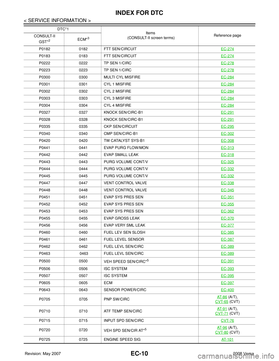
P0182 0182 FTT SEN/CIRCUITEC-274
P0183 0183 FTT SEN/CIRCUITEC-274
P0222 0222 TP SEN 1/CIRCEC-278
P0223 0223 TP SEN 1/CIRCEC-278
P0300 0300 MULTI CYL MISFIREEC-284
P0301 0301 CYL 1 MISFIREEC-284
P0302 0302 CYL 2 MISFIREEC-284
P0303 0303 CYL 3 MISFIREEC-284
P0304 0304 CYL 4 MISFIREEC-284
P0327 0327 KNOCK SEN/CIRC-B1EC-291
P0328 0328 KNOCK SEN/CIRC-B1EC-291
P0335 0335 CKP SEN/CIRCUITEC-295
P0340 0340 CMP SEN/CIRC-B1EC-302
P0420 0420 TW CATALYST SYS-B1EC-308
P0441 0441 EVAP PURG FLOW/MONEC-313
P0442 0442 EVAP SMALL LEAKEC-318
P0443 0443 PURG VOLUME CONT/VEC-325
P0444 0444 PURG VOLUME CONT/VEC-332
P0445 0445 PURG VOLUME CONT/VEC-332
P0447 0447 VENT CONTROL VALVEEC-338
P0448 0448 VENT CONTROL VALVEEC-345
P0451 0451 EVAP SYS PRES SENEC-351
P0452 0452 EVAP SYS PRES SENEC-355
P0453 0453 EVAP SYS PRES SENEC-362
P0455 0455 EVAP GROSS LEAKEC-370
P0456 0456 EVAP VERY SML LEAKEC-377
P0460 0460 FUEL LEV SEN SLOSHEC-385
P0461 0461 FUEL LEVEL SENSOREC-387
P0462 0462 FUEL LEVL SEN/CIRCEC-389
P0463 0463 FUEL LEVL SEN/CIRCEC-389
P0500 0500
VEH SPEED SEN/CIRC*5EC-391
P0506 0506 ISC SYSTEMEC-393
P0507 0507 ISC SYSTEMEC-395
P0605 0605 ECMEC-397
P0643 0643 SENSOR POWER/CIRCEC-400
P0705 0705 PNP SW/CIRCAT- 8 6 (A/T),
CVT-65
(CVT)
P0710 0710 ATF TEMP SEN/CIRCAT- 9 1
(A/T),
CVT-71
(CVT)
P0715 0715 INPUT SPD SEN/CIRCCVT-76
P0720 0720
VEH SPD SEN/CIR AT*5AT- 9 6 (A/T),
CVT-80
(CVT)
P0725 0725 ENGINE SPEED SIGAT- 1 0 1
DTC*1
Items
(CONSULT-II screen terms)Reference page
CONSULT-II
GST*
2ECM*3
Page 1089 of 2771
INDEX FOR DTC
EC-15
< SERVICE INFORMATION >
C
D
E
F
G
H
I
J
K
L
MA
EC
N
P O
*1: 1st trip DTC No. is the same as DTC No.
*2: This number is prescribed by SAE J2012.
*3: In Diagnostic Test Mode II (Self-diagnostic results), this number is controlled by NISSAN.
*4: The troubleshooting for this DTC needs CONSULT-II.
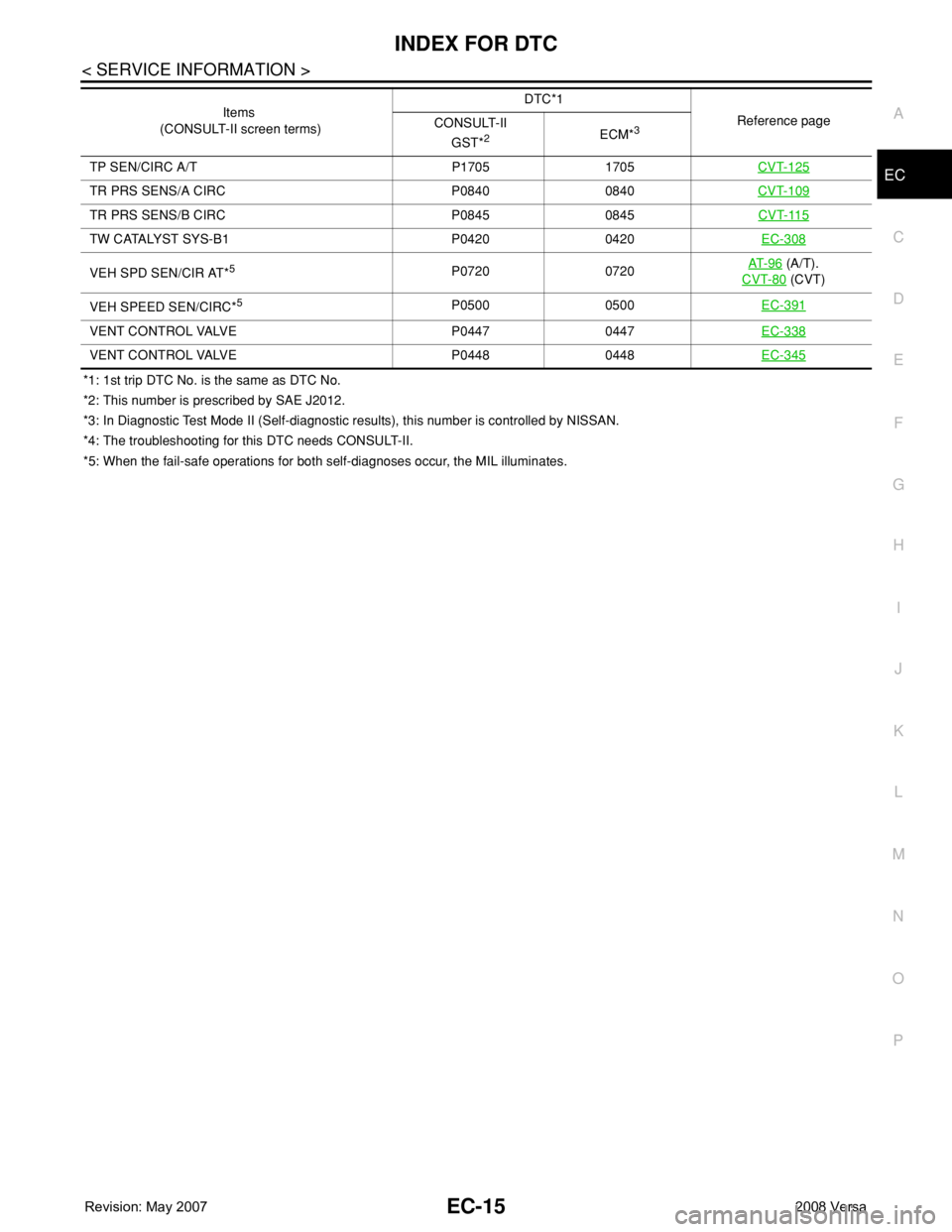
*5: When the fail-safe operations for both self-diagnoses occur, the MIL illuminates.TP SEN/CIRC A/T P1705 1705CVT-125
TR PRS SENS/A CIRC P0840 0840CVT-109
TR PRS SENS/B CIRC P0845 0845CVT-115
TW CATALYST SYS-B1 P0420 0420EC-308
VEH SPD SEN/CIR AT*5P0720 0720AT- 9 6 (A/T).
CVT-80
(CVT)
VEH SPEED SEN/CIRC*
5P0500 0500EC-391
VENT CONTROL VALVE P0447 0447EC-338
VENT CONTROL VALVE P0448 0448EC-345
Items
(CONSULT-II screen terms)DTC*1
Reference page
CONSULT-II
GST*
2ECM*3
Page 1122 of 2771

EC-48
< SERVICE INFORMATION >
ON BOARD DIAGNOSTIC (OBD) SYSTEM
FUEL SYS-LEAN-B1 P0171 0171 — — 2×EC-257
FUEL SYS-RICH-B1 P0172 0172 — — 2×EC-264
FTT SENSOR P0181 0181 — — 2×EC-270
FTT SEN/CIRCUIT P0182 0182 — — 2×EC-274
FTT SEN/CIRCUIT P0183 0183 — — 2×EC-274
TP SEN 1/CIRC P0222 0222 — — 1×EC-278
TP SEN 1/CIRC P0223 0223 — — 1×EC-278
MULTI CYL MISFIRE P0300 0300 — — 2×EC-284
CYL 1 MISFIRE P0301 0301 — — 2×EC-284
CYL 2 MISFIRE P0302 0302 — — 2×EC-284
CYL 3 MISFIRE P0303 0303 — — 2×EC-284
CYL 4 MISFIRE P0304 0304 — — 2×EC-284
KNOCK SEN/CIRC-B1 P0327 0327 — — 2 —EC-291
KNOCK SEN/CIRC-B1 P0328 0328 — — 2 —EC-291
CKP SEN/CIRCUIT P0335 0335 — — 2×EC-295
CMP SEN/CIRC-B1 P0340 0340 — — 2×EC-302
TW CATALYST SYS-B1 P0420 0420× ×2×EC-308
EVAP PURG FLOW/MON P0441 0441××2×EC-313
EVAP SMALL LEAK P0442 0442××2×EC-318
PURG VOLUME CONT/V P0443 0443 — — 2×EC-325
PURG VOLUME CONT/V P0444 0444 — — 2×EC-332
PURG VOLUME CONT/V P0445 0445 — — 2×EC-332
VENT CONTROL VALVE P0447 0447 — — 2×EC-338
VENT CONTROL VALVE P0448 0448 — — 2×EC-345
EVAP SYS PRES SEN P0451 0451 — — 2×EC-351
EVAP SYS PRES SEN P0452 0452 — — 2×EC-355
EVAP SYS PRES SEN P0453 0453 — — 2×EC-362
EVAP GROSS LEAK P0455 0455 — — 2×EC-370
EVAP VERY SML LEAK P0456 0456
×*6×2×EC-377
FUEL LEV SEN SLOSH P0460 0460 — — 2×EC-385
FUEL LEVEL SENSOR P0461 0461 — — 2×EC-387
FUEL LEVL SEN/CIRC P0462 0462 — — 2×EC-389
FUEL LEVL SEN/CIRC P0463 0463 — — 2×EC-389
VEH SPEED SEN/CIRC*7P0500 0500 — — 2×EC-391
ISC SYSTEM P0506 0506 — — 2×EC-393
ISC SYSTEM P0507 0507 — — 2×EC-395
ECM P0605 0605 — — 1 or 2 — or ×EC-397
SENSOR POWER/CIRC P0643 0643 — — 1×EC-400
PNP SW/CIRC P0705 0705 — — 2×AT- 8 6 (A/T),
CVT-65
(CVT)
ATF TEMP SEN/CIRC P0710 0710 — — 2×AT- 9 1
(A/T),
CVT-71
(CVT)
INPUT SPD SEN/CIRC P0715 0715 — — 2×CVT-76
Items
(CONSULT-II screen terms)DTC*
1
SRT codeTest value/
Test limit
(GST only)TripMIL lighting
upReference
page CONSULT-II
GST*
2ECM*3
Page 1161 of 2771

TROUBLE DIAGNOSIS
EC-87
< SERVICE INFORMATION >
C
D
E
F
G
H
I
J
K
L
MA
EC
N
P O
Fail-Safe ChartINFOID:0000000001702588
When the DTC listed below is detected, the ECM enters fail-safe mode and the MIL lights up.
Priority Detected items (DTC)
1 • U1000 U1001 CAN communication line
• U1010 CAN communication
• P0101 P0102 P0103 Mass air flow sensor
• P0112 P0113 P0127 Intake air temperature sensor
• P0117 P0118 P0125 Engine coolant temperature sensor
• P0122 P0123 P0222 P0223 P1225 P1226 P2135 Throttle position sensor
• P0128 Thermostat function
• P0181 P0182 P0183 Fuel tank temperature sensor
• P0327 P0328 Knock sensor
• P0335 Crankshaft position sensor (POS)
• P0340 Camshaft position sensor (PHASE)
• P0460 P0461 P0462 P0463 Fuel level sensor
• P0500 Vehicle speed sensor
• P0605 ECM
• P0643 Sensor power supply
• P0705 P0850 Park/neutral position (PNP) switch
• P1610 - P1615 NATS
• P2122 P2123 P2127 P2128 P2138 Accelerator pedal position sensor
2 • P0031 P0032 Air fuel ratio (A/F) sensor 1 heater
• P0037 P0038 Heated oxygen sensor 2 heater
• P0075 Intake valve timing control solenoid valve
• P0130 P0131 P0132 P0133 P2A00 Air fuel ratio (A/F) sensor 1
• P0137 P0138 P0139 Heated oxygen sensor 2
• P0441 EVAP control system purge flow monitoring
• P0443 P0444 P0445 EVAP canister purge volume control solenoid valve
• P0447 P0448 EVAP canister vent control valve
• P0451 P0452 P0453 EVAP control system pressure sensor
• P1217 Engine over temperature (OVERHEAT)
• P1805 Brake switch
• P2100 P2103 Throttle control motor relay
• P2101 Electric throttle control function
• P2118 Throttle control motor
3 • P0011 Intake valve timing control
• P0171 P0172 Fuel injection system function
• P0300 - P0304 Misfire
• P0420 Three way catalyst function
• P0442 P0456 EVAP control system (SMALL LEAK, VERY SMALL LEAK)
• P0455 EVAP control system (GROSS LEAK)
• P0506 P0507 Idle speed control system
• P0710 P0715 P0720 P0725 P0731 P0732 P0733 P0734 P0740 P0744 P0745 P0746 P0750 P0755 P0776 P0778
P0840 P0845 P1705 P1740 P1760 P1777 P1778 A/T or CVT related sensors, solenoid valves and switches
• P1148 Closed loop control
• P1421 Cold start control
• P1564 ASCD steering switch
• P1572 ASCD brake switch
• P1574 ASCD vehicle speed sensor
• P1715 Turbine revolution sensor (A/T), Primary speed sensor (CVT)
• P2119 Electric throttle control actuator
DTC No. Detected items Engine operating condition in fail-safe mode
P0102
P0103Mass air flow sensor circuit Engine speed will not rise more than 2,400 rpm due to the fuel cut.
Page 1465 of 2771
DTC P0500 VSS
EC-391
< SERVICE INFORMATION >
C
D
E
F
G
H
I
J
K
L
MA
EC
N
P O
DTC P0500 VSS
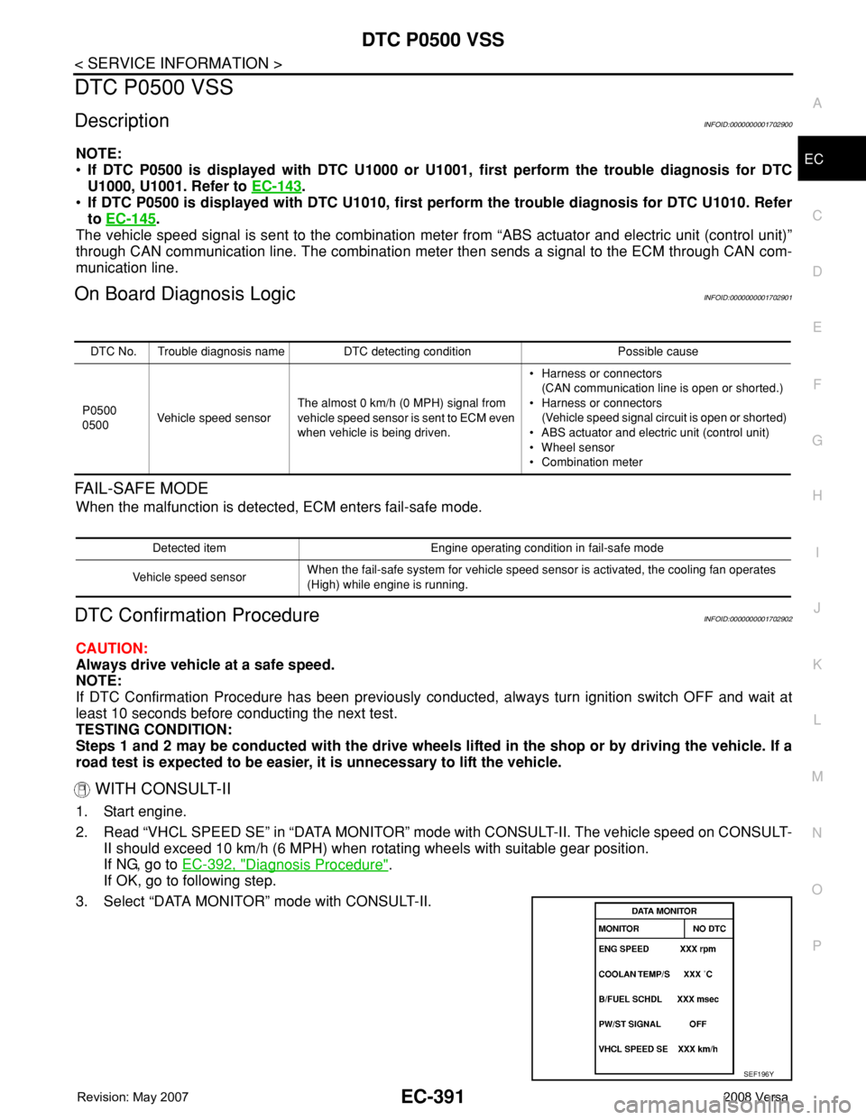
DescriptionINFOID:0000000001702900
NOTE:
•If DTC P0500 is displayed with DTC U1000 or U1001, first perform the trouble diagnosis for DTC
U1000, U1001. Refer to EC-143
.
•If DTC P0500 is displayed with DTC U1010, first perform the trouble diagnosis for DTC U1010. Refer
to EC-145
.
The vehicle speed signal is sent to the combination meter from “ABS actuator and electric unit (control unit)”
through CAN communication line. The combination meter then sends a signal to the ECM through CAN com-
munication line.
On Board Diagnosis LogicINFOID:0000000001702901
FAIL-SAFE MODE
When the malfunction is detected, ECM enters fail-safe mode.
DTC Confirmation ProcedureINFOID:0000000001702902
CAUTION:
Always drive vehicle at a safe speed.
NOTE:
If DTC Confirmation Procedure has been previously conducted, always turn ignition switch OFF and wait at
least 10 seconds before conducting the next test.
TESTING CONDITION:
Steps 1 and 2 may be conducted with the drive wheels lifted in the shop or by driving the vehicle. If a
road test is expected to be easier, it is unnecessary to lift the vehicle.
WITH CONSULT-II
1. Start engine.
2. Read “VHCL SPEED SE” in “DATA MONITOR” mode with CONSULT-II. The vehicle speed on CONSULT-
II should exceed 10 km/h (6 MPH) when rotating wheels with suitable gear position.
If NG, go to EC-392, "
Diagnosis Procedure".
If OK, go to following step.
3. Select “DATA MONITOR” mode with CONSULT-II.
DTC No. Trouble diagnosis name DTC detecting condition Possible cause
P0500
0500Vehicle speed sensorThe almost 0 km/h (0 MPH) signal from
vehicle speed sensor is sent to ECM even
when vehicle is being driven.• Harness or connectors
(CAN communication line is open or shorted.)
• Harness or connectors
(Vehicle speed signal circuit is open or shorted)
• ABS actuator and electric unit (control unit)
• Wheel sensor
• Combination meter
Detected item Engine operating condition in fail-safe mode
Vehicle speed sensorWhen the fail-safe system for vehicle speed sensor is activated, the cooling fan operates
(High) while engine is running.
SEF196Y
Page 1466 of 2771
EC-392
< SERVICE INFORMATION >
DTC P0500 VSS
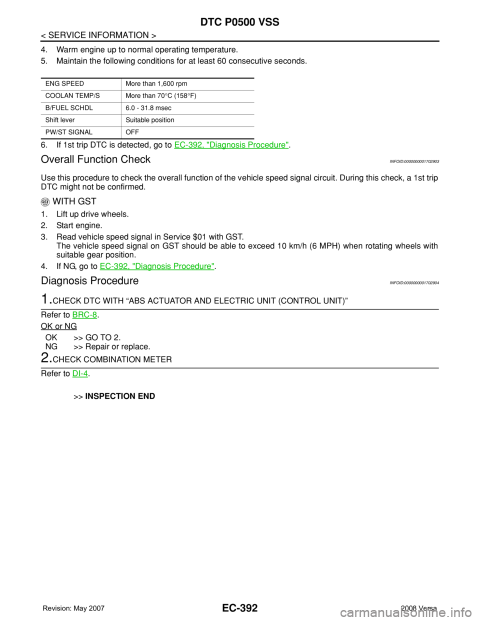
4. Warm engine up to normal operating temperature.
5. Maintain the following conditions for at least 60 consecutive seconds.
6. If 1st trip DTC is detected, go to EC-392, "
Diagnosis Procedure".
Overall Function CheckINFOID:0000000001702903
Use this procedure to check the overall function of the vehicle speed signal circuit. During this check, a 1st trip
DTC might not be confirmed.
WITH GST
1. Lift up drive wheels.
2. Start engine.
3. Read vehicle speed signal in Service $01 with GST.
The vehicle speed signal on GST should be able to exceed 10 km/h (6 MPH) when rotating wheels with
suitable gear position.
4. If NG, go to EC-392, "
Diagnosis Procedure".
Diagnosis ProcedureINFOID:0000000001702904
1.CHECK DTC WITH “ABS ACTUATOR AND ELECTRIC UNIT (CONTROL UNIT)”
Refer to BRC-8
.
OK or NG
OK >> GO TO 2.
NG >> Repair or replace.
2.CHECK COMBINATION METER
Refer to DI-4
.
>>INSPECTION END
ENG SPEED More than 1,600 rpm
COOLAN TEMP/S More than 70°C (158°F)
B/FUEL SCHDL 6.0 - 31.8 msec
Shift lever Suitable position
PW/ST SIGNAL OFF
Page 1521 of 2771
DTC P1574 ASCD VEHICLE SPEED SENSOR
EC-447
< SERVICE INFORMATION >
C
D
E
F
G
H
I
J
K
L
MA
EC
N
P O
DTC P1574 ASCD VEHICLE SPEED SENSOR
Component DescriptionINFOID:0000000001702965
The ECM receives two vehicle speed sensor signals via CAN communication line. One is sent from combina-
tion meter, and the other is from TCM (Transmission control module). The ECM uses these signals for ASCD
control. Refer to EC-28
for ASCD functions.
On Board Diagnosis LogicINFOID:0000000001702966
This self-diagnosis has the one trip detection logic.
The MIL will not light up for this diagnosis.
NOTE:
•If DTC P1574 is displayed with DTC U1000, U1001, first perform the trouble diagnosis for DTC U1000,
U1001. Refer to EC-143
.
•If DTC P1574 is displayed with DTC U1010, first perform the trouble diagnosis for DTC U1010. Refer
to EC-145
.
•If DTC P1574 is displayed with DTC P0500, first perform the trouble diagnosis for DTC P0500. Refer
to EC-391
.
•If DTC P1574 is displayed with DTC P0605, first perform the trouble diagnosis for DTC P0605. Refer
to EC-397
.
DTC Confirmation ProcedureINFOID:0000000001702967
CAUTION:
Always drive vehicle at a safe speed.
NOTE:
If DTC Confirmation Procedure has been previously conducted, always turn ignition switch OFF and wait at
least 10 seconds before conducting the next test.
TESTING CONDITION:
Step 3 may be conducted with the drive wheels lifted in the shop or by driving the vehicle. If a road test
is expected to be easier, it is unnecessary to lift the vehicle.
WITH CONSULT-II
1. Start engine.
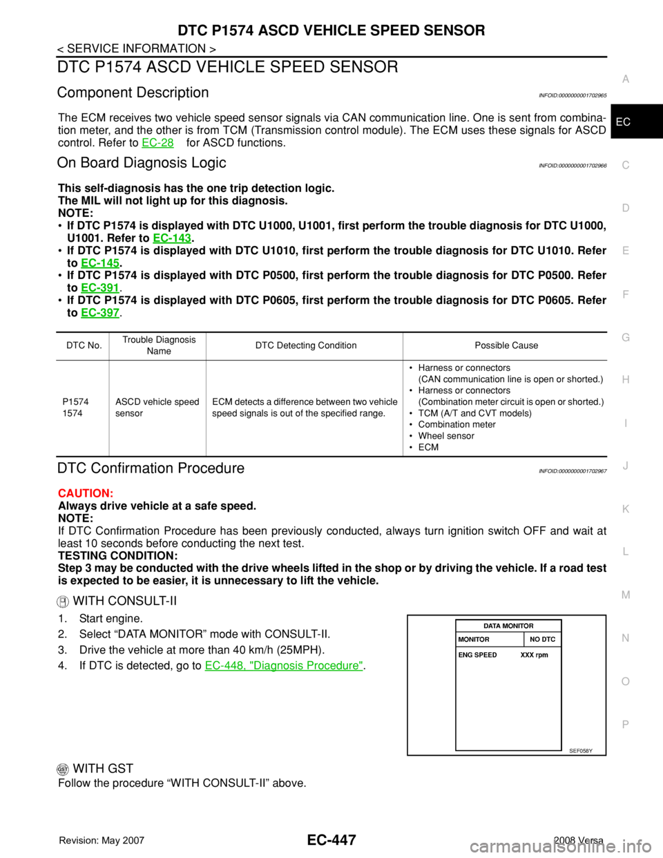
2. Select “DATA MONITOR” mode with CONSULT-II.
3. Drive the vehicle at more than 40 km/h (25MPH).
4. If DTC is detected, go to EC-448, "
Diagnosis Procedure".
WITH GST
Follow the procedure “WITH CONSULT-II” above.
DTC No.Trouble Diagnosis
NameDTC Detecting Condition Possible Cause
P1574
1574ASCD vehicle speed
sensorECM detects a difference between two vehicle
speed signals is out of the specified range.• Harness or connectors
(CAN communication line is open or shorted.)
• Harness or connectors
(Combination meter circuit is open or shorted.)
• TCM (A/T and CVT models)
• Combination meter
• Wheel sensor
•ECM
SEF058Y