2008 NISSAN TIIDA engine mount
[x] Cancel search: engine mountPage 380 of 2771
AUDIO
AV-21
< SERVICE INFORMATION >
C
D
E
F
G
H
I
J
L
MA
B
AV
N
O
P
and M45 first followed by M43 last. If the subwoofer is inoperative, be sure to check this condition. Refer to AV-
34, "Sound Is Not Heard from Subwoofer (Premium System)" .
• The majority of the audio malfunctions are the result of outside causes (damaged CD, electromagnetic inter-
ference, etc.). Check the symptoms below to diagnose the malfunction.
• The vehicle itself can be a source of noise if noise prevention parts or electrical equipment is malfunctioning.
Check if noise is caused and/or changed by engine speed, ignition switch turned to each position, and oper-
ation of each piece of electrical equipment, and then determine the cause.
NOTE:
Noise resulting from variations in field strength, such as fading noise and multi-path noise, or external noise
from trains and other sources. It is not a malfunction.
• Fading noise: This noise occurs because of variations in the field strength in a narrow range due to moun-
tains or buildings blocking the signal.
• Multi-path noise: This noise results from the waves sent directly from the broadcast station arriving at the
antenna at a different time from the waves that reflect off of mountains or buildings.
Noise InspectionINFOID:0000000001704662
The vehicle itself can be a source of noise if noise prevention parts or electrical equipment is malfunctioning.
Check if noise is caused and/or changed by engine speed, ignition switch turned to each position, and opera-
tion of each piece of electrical equipment, and determine the cause.
NOTE:
The source of the noise can be found easily by listening to the noise while removing the fuses of electrical
components, one by one.
TYPE OF NOISE AND POSSIBLE CAUSE
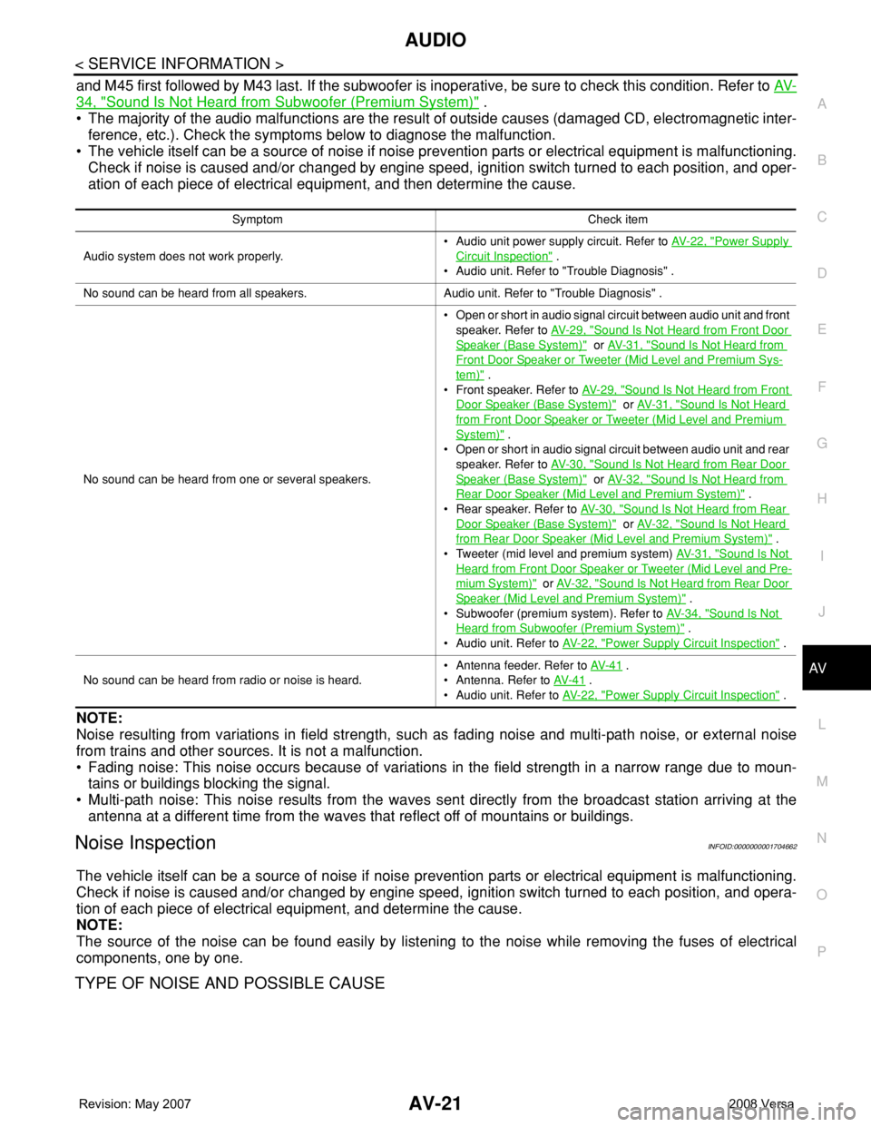
Symptom Check item
Audio system does not work properly.• Audio unit power supply circuit. Refer to AV- 2 2 , "
Power Supply
Circuit Inspection" .
• Audio unit. Refer to "Trouble Diagnosis" .
No sound can be heard from all speakers. Audio unit. Refer to "Trouble Diagnosis" .
No sound can be heard from one or several speakers.• Open or short in audio signal circuit between audio unit and front
speaker. Refer to AV- 2 9 , "
Sound Is Not Heard from Front Door
Speaker (Base System)" or AV- 3 1 , "Sound Is Not Heard from
Front Door Speaker or Tweeter (Mid Level and Premium Sys-
tem)" .
• Front speaker. Refer to AV- 2 9 , "
Sound Is Not Heard from Front
Door Speaker (Base System)" or AV- 3 1 , "Sound Is Not Heard
from Front Door Speaker or Tweeter (Mid Level and Premium
System)" .
• Open or short in audio signal circuit between audio unit and rear
speaker. Refer to AV- 3 0 , "
Sound Is Not Heard from Rear Door
Speaker (Base System)" or AV- 3 2 , "Sound Is Not Heard from
Rear Door Speaker (Mid Level and Premium System)" .
• Rear speaker. Refer to AV- 3 0 , "
Sound Is Not Heard from Rear
Door Speaker (Base System)" or AV- 3 2 , "Sound Is Not Heard
from Rear Door Speaker (Mid Level and Premium System)" .
• Tweeter (mid level and premium system) AV- 3 1 , "
Sound Is Not
Heard from Front Door Speaker or Tweeter (Mid Level and Pre-
mium System)" or AV- 3 2 , "Sound Is Not Heard from Rear Door
Speaker (Mid Level and Premium System)" .
• Subwoofer (premium system). Refer to AV- 3 4 , "
Sound Is Not
Heard from Subwoofer (Premium System)" .
• Audio unit. Refer to AV- 2 2 , "
Power Supply Circuit Inspection" .
No sound can be heard from radio or noise is heard.• Antenna feeder. Refer to AV- 4 1
.
• Antenna. Refer to AV- 4 1
.
• Audio unit. Refer to AV- 2 2 , "
Power Supply Circuit Inspection" .
Page 444 of 2771

BL-10
< SERVICE INFORMATION >
SQUEAK AND RATTLE TROUBLE DIAGNOSES
Most of these incidents can be repaired by adjusting, securing or insulating the item(s) or component(s) caus-
ing the noise.
SUNROOF/HEADLINING
Noises in the sunroof/headlining area can often be traced to one of the following:
1. Sunroof lid, rail, linkage or seals making a rattle or light knocking noise
2. Sun visor shaft shaking in the holder
3. Front or rear windshield touching headliner and squeaking
Again, pressing on the components to stop the noise while duplicating the conditions can isolate most of these
incidents. Repairs usually consist of insulating with felt cloth tape.
OVERHEAD CONSOLE (FRONT AND REAR)
Overhead console noises are often caused by the console panel clips not being engaged correctly. Most of
these incidents are repaired by pushing up on the console at the clip locations until the clips engage.
In addition look for:
1. Loose harness or harness connectors.
2. Front console map/reading lamp lense loose.
3. Loose screws at console attachment points.
SEATS
When isolating seat noise it's important to note the position the seat is in and the load placed on the seat when
the noise is present. These conditions should be duplicated when verifying and isolating the cause of the
noise.
Cause of seat noise include:
1. Headrest rods and holder
2. A squeak between the seat pad cushion and frame
3. The rear seatback lock and bracket
These noises can be isolated by moving or pressing on the suspected components while duplicating the con-
ditions under which the noise occurs. Most of these incidents can be repaired by repositioning the component
or applying urethane tape to the contact area.
UNDERHOOD
Some interior noise may be caused by components under the hood or on the engine wall. The noise is then
transmitted into the passenger compartment.
Causes of transmitted underhood noise include:
1. Any component mounted to the engine wall
2. Components that pass through the engine wall
3. Engine wall mounts and connectors
4. Loose radiator mounting pins
5. Hood bumpers out of adjustment
6. Hood striker out of adjustment
These noises can be difficult to isolate since they cannot be reached from the interior of the vehicle. The best
method is to secure, move or insulate one component at a time and test drive the vehicle. Also, engine RPM
or load can be changed to isolate the noise. Repairs can usually be made by moving, adjusting, securing, or
insulating the component causing the noise.
Page 662 of 2771

BL-228
< SERVICE INFORMATION >
BODY REPAIR
4. Front pillar inner reinforcement (RH&LH)
5. Lower dash reinforcement
6. 4th crossmember (RH&LH)
7. Front side member rear extension (RH&LH)
8. 3rd crossmember (RH&LH)
9. Front seat outer rear bracket (RH&LH)
10. Front seat inner rear bracket (RH&LH)
11. 2nd crossmember (RH&LH)
12. Front seat outer front bracket (RH&LH)
13. Front seat inner front bracket (RH&LH)
14. Fender bracket (RH&LH)
15. Strut housing assembly RH
16. Cowl top side upper (RH&LH)
17. Front strut housing (RH&LH)
18. Upper torque rod reinforcement
19. Closing plate assembly RH
20. Engine mount reinforcement
21. Strut tower front reinforcement RH
22. Front hoodledge lower RH
23. Frame bracket outer (RH&LH)
24. Front bumper support bracket (RH&LH)
25. Closing plate (RH&LH)
26. Front suspension rear bracket (RH&LH)
27. Front side member outrigger (RH&LH)
28. Front side member assembly (RH&LH)
29. Front side member (RH&LH)
30. Frame bracket (RH&LH)
31. Closing plate assembly LH
32. Hoodledge connector (RH&LH)
33. Radiator core side support (RH&LH)
34. Radiator core support upper (RH&LH)
35. Hoodledge upper (RH&LH)
36. Hoodledge reinforcement assembly (RH&LH)
37. Dash side (RH&LH)
38. Dash side assembly (RH& LH)
39. Front floor reinforcement (RH&LH)
40. Front floor front (RH&LH)
41. Front floor center
42. Rear seat crossmember
43. Rear center crossmember
44. Rear seat upper crossmember
45. Rear side member (RH&LH)
46. Sill inner extension (RH&LH)
47. Rear side member extension (RH&LH)
48. Rear side member assembly (RH & LH)
49. Rear floor front
50. Rear floor front assembly
51. Rear floor side (RH&LH)
52. Rear floor rear
Page 795 of 2771
![NISSAN TIIDA 2008 Service Repair Manual BRC-30
< SERVICE INFORMATION >[ABS]
TROUBLE DIAGNOSES FOR SYMPTOMS
2. Drive vehicle and check brake operation.
NOTE:
• Stopping distance may be longer than vehicles without ABS when road condition i](/manual-img/5/57399/w960_57399-794.png "NISSAN TIIDA 2008 Service Repair Manual BRC-30
< SERVICE INFORMATION >[ABS]
TROUBLE DIAGNOSES FOR SYMPTOMS
2. Drive vehicle and check brake operation.
NOTE:
• Stopping distance may be longer than vehicles without ABS when road condition i")
BRC-30
< SERVICE INFORMATION >[ABS]
TROUBLE DIAGNOSES FOR SYMPTOMS
2. Drive vehicle and check brake operation.
NOTE:
• Stopping distance may be longer than vehicles without ABS when road condition is slippery.
• Driving the vehicle with the ABS actuator and electric unit (control unit) disconnected may induce DTCs
in electrical control units using CAN communication. After the inspection, clear all DTCs. Refer to LAN-
6, "System Description".
OK or NG
OK >> GO TO 4.
NG >> Perform Basic Inspection. Refer to BRC-16, "
Basic Inspection".
4.CHECK WHEEL SENSORS
Check the following.
• Wheel sensor mounting for looseness
• Wheel sensors for physical damage
• Wheel sensor connectors for terminal damage or loose connections
• Sensor rotor and mount for physical damage
OK or NG
OK >> Check ABS actuator and electric unit (control unit) connector terminals for deformation, discon-
nection, looseness or damage. Reconnect ABS actuator and electric unit (control unit) harness
connector. Then retest.
NG >> Repair or replace as necessary.
Long Stopping DistanceINFOID:0000000001703847
1.CHECK BASE BRAKING SYSTEM PERFORMANCE
1. Disable ABS by disconnecting ABS actuator and electric unit (control unit) connector.
2. Drive vehicle and check brake operation.
NOTE:
• Stopping distance may be longer than vehicles without ABS when road condition is slippery.
• Driving the vehicle with the ABS actuator and electric unit (control unit) disconnected may induce DTCs
in electrical control units using CAN communication. After the inspection, clear all DTCs. Refer to LAN-
6, "System Description".
OK or NG
OK >> Go to BRC-29, "ABS Works Frequently".
NG >> Perform Basic Inspection. Refer to BRC-16, "
Basic Inspection".
ABS Does Not WorkINFOID:0000000001703848
CAUTION:
The ABS does not operate when the vehicle speed is 10 km/h (6 MPH) or less.
1.CHECK WARNING LAMP ACTIVATION
Turn ignition switch ON and check for warning lamp activation.
• Warning lamp should activate for approximately 2 seconds after turning the ignition switch ON.
OK or NG
OK >> Carry out self-diagnosis. Refer to BRC-18, "CONSULT-III Function (ABS)".
NG >> Go to BRC-16, "
Basic Inspection".
Pedal Vibration or ABS Operation NoiseINFOID:0000000001703849
NOTE:
During ABS activation, pedal vibration may be felt and a noise may be heard. This is normal and does not indi-
cate a malfunction.
1.CHECK SYMPTOM
1. Apply brake.
2. Start engine.
Does the symptom occur only when engine is started?
YES >> Carry out self-diagnosis. Refer to BRC-18, "CONSULT-III Function (ABS)".
Page 800 of 2771
![NISSAN TIIDA 2008 Service Repair Manual ACTUATOR AND ELECTRIC UNIT (ASSEMBLY)
BRC-35
< SERVICE INFORMATION >[ABS]
C
D
E
G
H
I
J
K
L
MA
B
BRC
N
O
P
ACTUATOR AND ELECTRIC UNIT (ASSEMBLY)
Removal and InstallationINFOID:0000000001703852
CAUTION](/manual-img/5/57399/w960_57399-799.png "NISSAN TIIDA 2008 Service Repair Manual ACTUATOR AND ELECTRIC UNIT (ASSEMBLY)
BRC-35
< SERVICE INFORMATION >[ABS]
C
D
E
G
H
I
J
K
L
MA
B
BRC
N
O
P
ACTUATOR AND ELECTRIC UNIT (ASSEMBLY)
Removal and InstallationINFOID:0000000001703852
CAUTION")
ACTUATOR AND ELECTRIC UNIT (ASSEMBLY)
BRC-35
< SERVICE INFORMATION >[ABS]
C
D
E
G
H
I
J
K
L
MA
B
BRC
N
O
P
ACTUATOR AND ELECTRIC UNIT (ASSEMBLY)
Removal and InstallationINFOID:0000000001703852
CAUTION:
• Before servicing, disconnect battery cables.
• To remove brake tube, use flare nut wrench to prevent flare nuts and brake tube from being dam-
aged. To install, use flare nut torque wrench, tighten flare nut to the specified torque. Refer to BR-10,
"Hydraulic Circuit" .
• Do not apply excessive impact to ABS actuator and electric unit (control unit), such as dropping it.
• Do not remove and install actuator by holding harness.
• After work is completed, bleed air from brake tube and hose. Refer to BR-8, "
Bleeding Brake Sys-
tem" .
REMOVAL
1. Disconnect ABS actuator and electric unit (control unit) connector.
2. Loosen brake tube flare nuts, then remove brake tubes from ABS actuator and electric unit (control unit).
3. Remove brake booster hose from engine. Refer to BR-21, "
Removal and Installation" .
4. Remove ABS actuator and electric unit (control unit) bracket mounting bolts.
5. Remove ABS actuator and electric unit (control unit) from vehicle.
INSTALLATION
1. To front right 2. To rear left 3. To rear right
4. To front left 5. From master cylinder primary side 6. From master cylinder secondary
side
7. ABS actuator and electric unit (con-
trol unit)8. Harness connector : Front
Refer to GI section for symbol marks in the figure.
WFIA0506E
Page 805 of 2771

CL-4
< SERVICE INFORMATION >
NOISE, VIBRATION AND HARSHNESS (NVH) TROUBLESHOOTING
NOISE, VIBRATION AND HARSHNESS (NVH) TROUBLESHOOTING
NVH Troubleshooting ChartINFOID:0000000001703116
Use the chart below to help you find the cause of the symptom. The numbers indicate the order of the inspec-
tion. If necessary, repair or replace these parts.
Reference pageCL-5CL-8EM-72CL-11CL-13EM-93
SUSPECTED PARTS (Possible cause)
CLUTCH PEDAL (Inspection and adjustment)
CLUTCH LINE (Air in line)
ENGINE MOUNTING (Loose)
CSC (Concentric slave cylinder) (Worn, dirty or damaged)
CLUTCH DISC (Out of true)
CLUTCH DISC (Runout is excessive)
CLUTCH DISC (Lining broken)
CLUTCH DISC (Dirty or burned)
CLUTCH DISC (Oily)
CLUTCH DISC (Worn out)
CLUTCH DISC (Hardened)
CLUTCH DISC (Lack of spline grease)
DIAPHRAGM SPRING (Damaged)
DIAPHRAGM SPRING (Out of tip alignment)
PRESSURE PLATE (Distortion)
FLYWHEEL (Distortion)
SymptomClutch grabs/chatters 1 2 2 2 2 2
Clutch pedal spongy 1
Clutch noisy 1
Clutch slips 1 2 2 3 4 5
Clutch does not disengage 12 55555 5667
Page 829 of 2771
CO-12
< SERVICE INFORMATION >
RADIATOR
Do not remove radiator cap when the engine is hot. Serious burns could occur from high-pressure
engine coolant escaping from radiator. Wrap a thick cloth around the cap. Slowly turn it a quarter of a
turn to release built-up pressure. Carefully remove radiator cap by turning it all the way.
REMOVAL
1. Drain engine coolant from radiator. Refer to CO-8, "Changing Engine Coolant".
CAUTION:
• Perform this step when engine is cold.
• Do not spill engine coolant on drive belt.
2. Remove air duct (inlet). Refer to EM-16
.
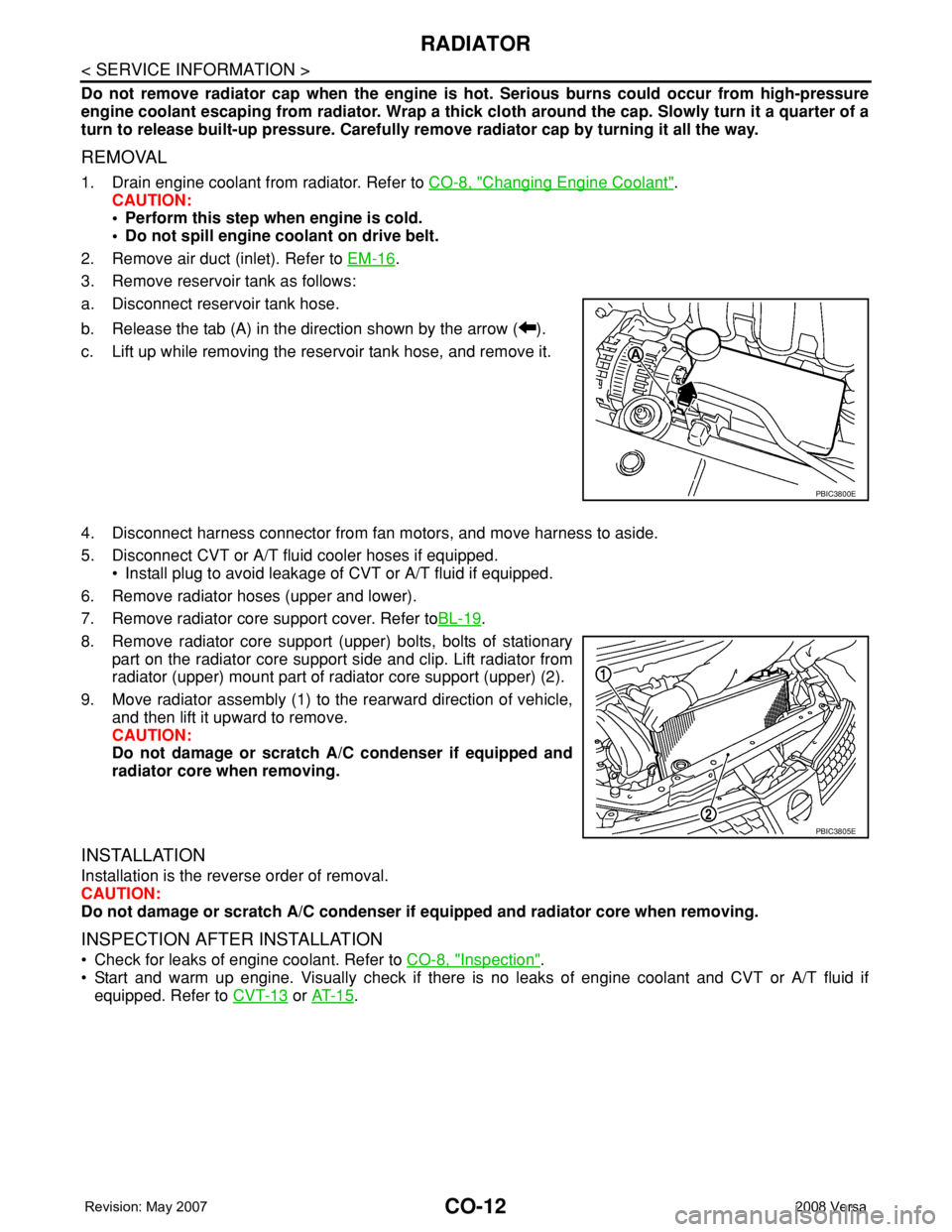
3. Remove reservoir tank as follows:
a. Disconnect reservoir tank hose.
b. Release the tab (A) in the direction shown by the arrow ( ).
c. Lift up while removing the reservoir tank hose, and remove it.
4. Disconnect harness connector from fan motors, and move harness to aside.
5. Disconnect CVT or A/T fluid cooler hoses if equipped.
• Install plug to avoid leakage of CVT or A/T fluid if equipped.
6. Remove radiator hoses (upper and lower).
7. Remove radiator core support cover. Refer toBL-19
.
8. Remove radiator core support (upper) bolts, bolts of stationary
part on the radiator core support side and clip. Lift radiator from
radiator (upper) mount part of radiator core support (upper) (2).
9. Move radiator assembly (1) to the rearward direction of vehicle,
and then lift it upward to remove.
CAUTION:
Do not damage or scratch A/C condenser if equipped and
radiator core when removing.
INSTALLATION
Installation is the reverse order of removal.
CAUTION:
Do not damage or scratch A/C condenser if equipped and radiator core when removing.
INSPECTION AFTER INSTALLATION
• Check for leaks of engine coolant. Refer to CO-8, "Inspection".
• Start and warm up engine. Visually check if there is no leaks of engine coolant and CVT or A/T fluid if
equipped. Refer to CVT-13
or AT- 1 5.
PBIC3800E
PBIC3805E
Page 834 of 2771
THERMOSTAT
CO-17
< SERVICE INFORMATION >
C
D
E
F
G
H
I
J
K
L
MA
CO
N
P O
THERMOSTAT
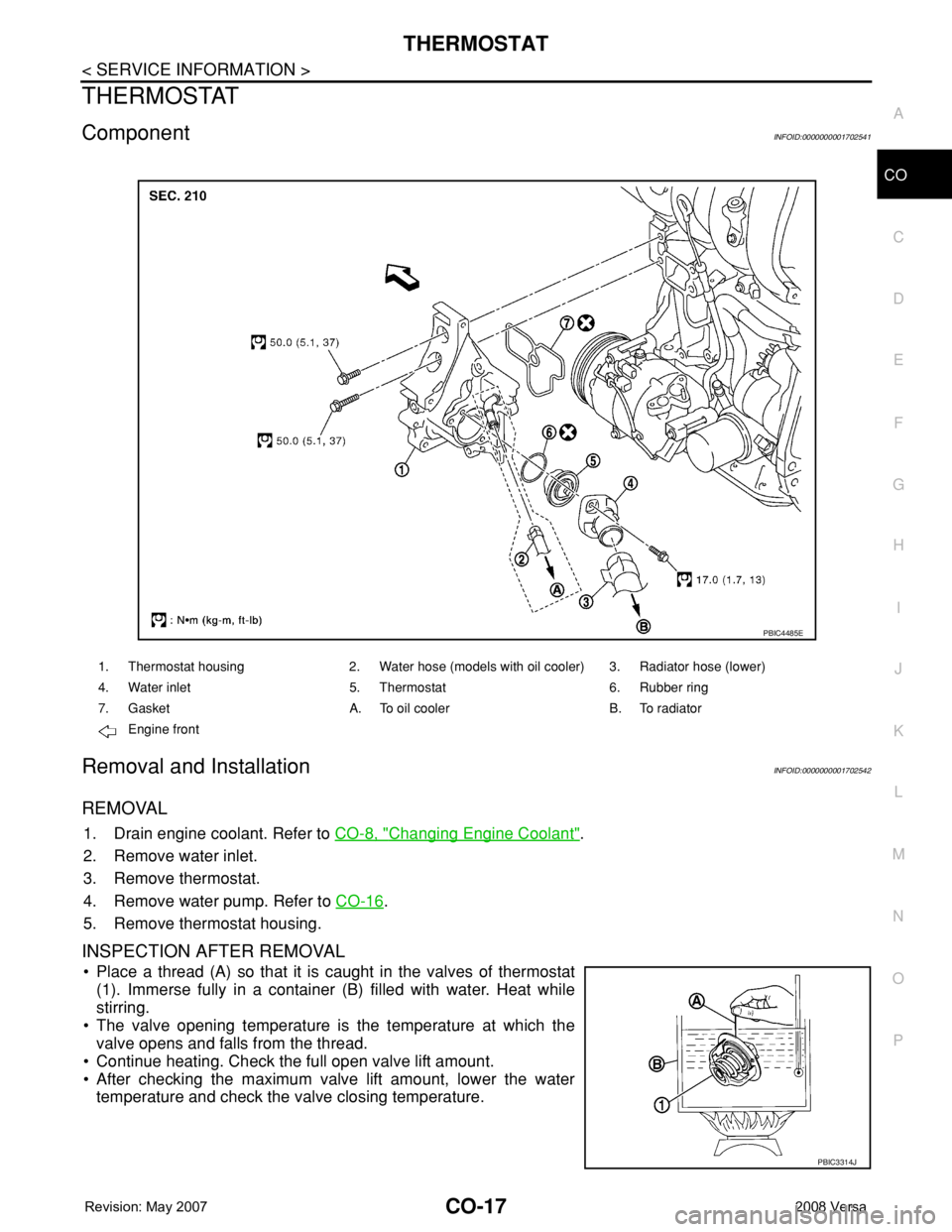
ComponentINFOID:0000000001702541
Removal and InstallationINFOID:0000000001702542
REMOVAL
1. Drain engine coolant. Refer to CO-8, "Changing Engine Coolant".
2. Remove water inlet.
3. Remove thermostat.
4. Remove water pump. Refer to CO-16
.
5. Remove thermostat housing.
INSPECTION AFTER REMOVAL
• Place a thread (A) so that it is caught in the valves of thermostat
(1). Immerse fully in a container (B) filled with water. Heat while
stirring.
• The valve opening temperature is the temperature at which the
valve opens and falls from the thread.
• Continue heating. Check the full open valve lift amount.
• After checking the maximum valve lift amount, lower the water
temperature and check the valve closing temperature.
1. Thermostat housing 2. Water hose (models with oil cooler) 3. Radiator hose (lower)
4. Water inlet 5. Thermostat 6. Rubber ring
7. Gasket A. To oil cooler B. To radiator
Engine front
PBIC4485E
PBIC3314J