2008 NISSAN TIIDA combination meter
[x] Cancel search: combination meterPage 515 of 2771

INTELLIGENT KEY SYSTEM
BL-81
< SERVICE INFORMATION >
C
D
E
F
G
H
J
K
L
MA
B
BL
N
O
P
When ignition switch turns to START position, BCM sends starter request signal to IPDM E/R. Then, engine
starts.
Even if Intelligent Key battery runs down, Intelligent key unit can start engine with mechanical key built Intelli-
gent Key. For details, refer toBL-210
.
All of the originally supplied Intelligent Key IDs (except for key) have been registered in Intelligent Key system.
If requested by the vehicle owner, a maximum of four Intelligent Key IDs can be registered into the Intelligent
Key system components.
List of Operation Related Parts
Parts marked with × are the parts related to operation.
WARNING CHIME/BUZZER/LAMPS FUNCTION
Operation Description
The following warning chime (combination meter), Intelligent Key warning buzzer (front door LH), Intelligent
Key warning buzzer (trunk)
*, warning lamps "KEY" and “P-SHIFT” (with CVT) or "LOCK" (with M/T) are given
to the user as warning information while using the intelligent key system.
• Ignition switch warning chime
• Ignition key warning chime
• OFF position warning chime
• Take away warning chime
• Door lock operation warning chime
• Intelligent key low battery warning
• P position warning (with CVT)
• LOCK position warning (with M/T)
NOTE:
For key-in-ignition warning chime related concerns only, refer to DI-41
.
* :
Sedan
Operation Condition
Engine start functions
Intelligent Key
Key switch
Ignition knob switch
Inside key antenna
Intelligent Key unit
CAN communication system
BCM
Combination meter
IPDM E/R
NATS antenna amp.
Steering lock solenoid
Engine start function by the Intelligent Key××××××××× ×
Engine start function by the mechanical key× ××× ×××
Operation ConditionWarning chime/buzzer Warning lamp
Chime
(combina-
tion meter)Buzzer(s) KEYLOCK
(M/T)P-SHIFT
(CVT)
Ignition switch warning chime• Mechanical key is out of ignition switch
(Key switch is OFF)
• Ignition switch is in the ACC, OFF or
LOCK position.
[ignition switch is pressed
(ignition knob switch is ON).]
• Driver door is open.activate — — — —
Ignition key warning chime
(When mechanical key is used)• Mechanical key is inserted in ignition
switch (key switch is ON).
• Ignition switch is in the ACC, OFF or
LOCK position.
• Driver door is open.activate — — — —
Page 517 of 2771
INTELLIGENT KEY SYSTEM
BL-83
< SERVICE INFORMATION >
C
D
E
F
G
H
J
K
L
MA
B
BL
N
O
P
CHANGE SETTINGS FUNCTION
The settings for each function can be changed with the CONSULT-III.
Changing Settings Using CONSULT-III
The settings for the Intelligent Key system functions can be changed using CONSULT-III (WORK SUPPORT).
Refer to BL-101, "
CONSULT-III Application Item".
NOTE:
Once a function setting is changed, it will remain effective even if the battery is disconnected.
INTELLIGENT KEY REGISTRATION
Intelligent Key-ID registration is performed using the CONSULT-III.
CAUTION:
• After a new Intelligent Key-ID is registered, be sure to check the function.
• When registering an additional Intelligent Key-ID, take any Intelligent Keys already registered and
Intelligent Keys for any other vehicles out of the vehicle before starting.
CONSULT-III can be used to check and delete Intelligent Key-IDs.
For further information, see the CONSULT-III Operation Manual NATS.
STEERING LOCK SOLENOID REGISTRATION
Steering Lock Solenoid ID Registration
CAUTION:
• The method for registering a steering lock solenoid ID depends on the status of the steering lock
solenoid and Intelligent Key unit (new or old unit).
• After registration is completed, press ignition switch with an Intelligent Key in the vehicle so that it
can be turned, and confirm that it cannot be turned even when ignition switch is pressed without an
Intelligent Key in the vehicle.
For further information, see the CONSULT-III Operation Manual NATS-IVIS/NVIS.
CAN Communication System DescriptionINFOID:0000000001704000
Refer to LAN-6.
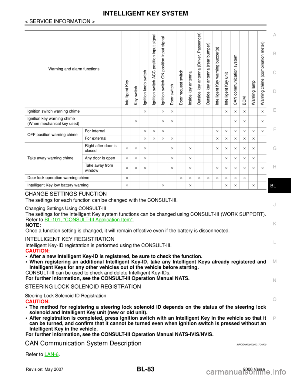
Warning and alarm functions
Intelligent Key
Key switch
Ignition knob switch
Ignition switch ACC position input signal
Ignition switch ON position input signal
Door switch
Door request switch
Inside key antenna
Outside key antenna (Driver, Passenger)
Outside key antenna (rear bumper)
Intelligent Key warning buzzer(s)
Intelligent Key unit
CAN communication system
BCM
Warning lamp
Warning chime (combination meter)
Ignition switch warning chime× ×× ××× ×
Ignition key warning chime
(When mechanical key used)××× ×××
OFF position warning chimeFor internal××× ××××××
For external×××× ×××××
Take away warning chimeRight after door is
closed××× × × ×××××
Any door is open××× × × ××××
Take away from
window××× × × ××××××
Door lock operation warning chime× ××××××××
Intelligent Key low battery warning××××××
Page 533 of 2771
INTELLIGENT KEY SYSTEM
BL-99
< SERVICE INFORMATION >
C
D
E
F
G
H
J
K
L
MA
B
BL
N
O
P
Terminal and Reference Value for BCMINFOID:0000000001704007
Refer to BCS-11, "Terminal and Reference Value for BCM".
Trouble Diagnosis ProcedureINFOID:0000000001704008
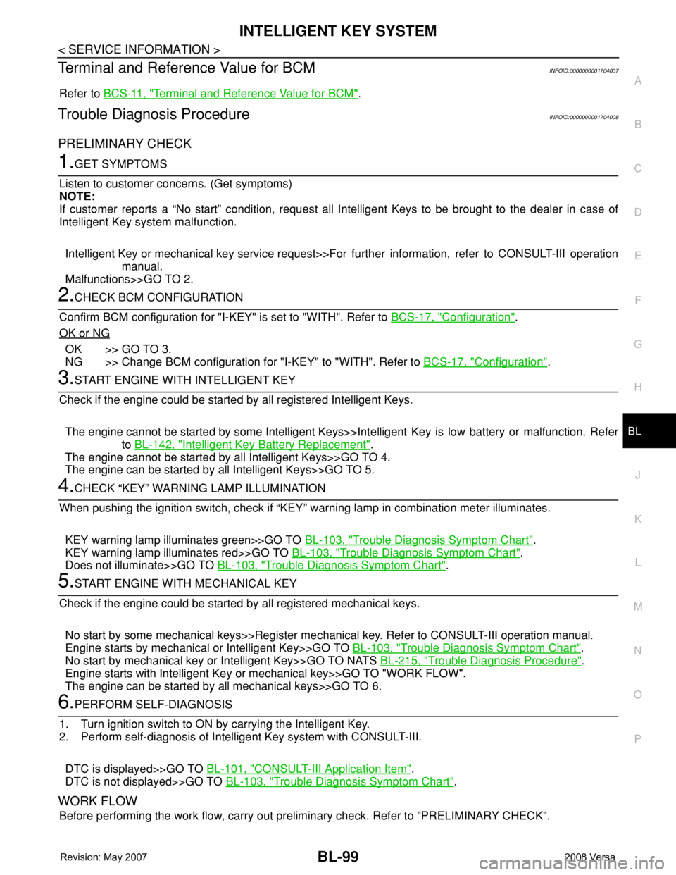
PRELIMINARY CHECK
1.GET SYMPTOMS
Listen to customer concerns. (Get symptoms)
NOTE:
If customer reports a “No start” condition, request all Intelligent Keys to be brought to the dealer in case of
Intelligent Key system malfunction.
Intelligent Key or mechanical key service request>>For further information, refer to CONSULT-III operation
manual.
Malfunctions>>GO TO 2.
2.CHECK BCM CONFIGURATION
Confirm BCM configuration for "I-KEY" is set to "WITH". Refer to BCS-17, "
Configuration".
OK or NG
OK >> GO TO 3.
NG >> Change BCM configuration for "I-KEY" to "WITH". Refer to BCS-17, "
Configuration".
3.START ENGINE WITH INTELLIGENT KEY
Check if the engine could be started by all registered Intelligent Keys.
The engine cannot be started by some Intelligent Keys>>Intelligent Key is low battery or malfunction. Refer
to BL-142, "
Intelligent Key Battery Replacement".
The engine cannot be started by all Intelligent Keys>>GO TO 4.
The engine can be started by all Intelligent Keys>>GO TO 5.
4.CHECK “KEY” WARNING LAMP ILLUMINATION
When pushing the ignition switch, check if “KEY” warning lamp in combination meter illuminates.
KEY warning lamp illuminates green>>GO TO BL-103, "
Trouble Diagnosis Symptom Chart".
KEY warning lamp illuminates red>>GO TO BL-103, "
Trouble Diagnosis Symptom Chart".
Does not illuminate>>GO TO BL-103, "
Trouble Diagnosis Symptom Chart".
5.START ENGINE WITH MECHANICAL KEY
Check if the engine could be started by all registered mechanical keys.
No start by some mechanical keys>>Register mechanical key. Refer to CONSULT-III operation manual.
Engine starts by mechanical or Intelligent Key>>GO TO BL-103, "
Trouble Diagnosis Symptom Chart".
No start by mechanical key or Intelligent Key>>GO TO NATS BL-215, "
Trouble Diagnosis Procedure".
Engine starts with Intelligent Key or mechanical key>>GO TO "WORK FLOW".
The engine can be started by all mechanical keys>>GO TO 6.
6.PERFORM SELF-DIAGNOSIS
1. Turn ignition switch to ON by carrying the Intelligent Key.
2. Perform self-diagnosis of Intelligent Key system with CONSULT-III.
DTC is displayed>>GO TO BL-101, "
CONSULT-III Application Item".
DTC is not displayed>>GO TO BL-103, "
Trouble Diagnosis Symptom Chart".
WORK FLOW
Before performing the work flow, carry out preliminary check. Refer to "PRELIMINARY CHECK".
Page 542 of 2771

BL-108
< SERVICE INFORMATION >
INTELLIGENT KEY SYSTEM
• Make sure that vehicle is under the condition shown in “Conditions of vehicle” before starting diagnosis, and
check each symptom.
• If the following “symptoms” are detected, check systems shown in the “Diagnosis/service procedure” column
in this order.
Conditions of Vehicle (Operating Conditions)
Warning chime/buzzer functions operating condition is extremely complicated, during operating confirmations,
reconfirm the list above twice in order to ensure proper operation.
Symptom Diagnosis/service procedure Reference page
Ignition switch warning chime does not oper-
ate.1. Check ignition knob switch.BL-113
2. Check door switch (hatchback).BL-114
3. Check door switch (sedan).BL-117
4. Check key switch.BL-110
5. Check Intelligent Key warning chime.BL-140
6. Replace Intelligent Key unit.BL-142
Ignition key warning chime does not operate.
(When mechanical key used).1. Check key switch (Intelligent Key unit input).BL-110
2. Check key switch (BCM input).BL-112
3. Check door switch (hatchback).BL-114
4. Check door switch (sedan).BL-117
5. Check Intelligent Key warning chime.BL-140
6. Replace Intelligent Key unit.BL-142
OFF position warning chime (For internal)
does not operate.1. Check ignition switch position.BL-134
2. Check ignition knob switch.BL-113
3. Check key switch.BL-110
4. Check combination meter warning chime.BL-140
5. Replace Intelligent Key unit.BL-142
OFF position warning
chime/buzzer (for ex-
ternal) does not oper-
ate.Both Intelligent Key
warning chime and
buzzer do not oper-
ate.1. Check ignition switch position.BL-134
2. Check ignition knob switch.BL-113
3. Check key switch.BL-110
4. Check Intelligent Key warning chime.BL-140
5. Check Intelligent Key warning buzzer(s).BL-125
6. Replace Intelligent Key unit.BL-142
Intelligent Key warn-
ing buzzer does not
operate.Check Intelligent Key warning buzzer(s).BL-125
Take away warning
chime/buzzer (door
open to close) does
not operate.Both Intelligent Key
warning chime and
buzzer do not oper-
ate.1. Check door switch (hatchback).BL-114
2. Check door switch (sedan).BL-117
3. Check inside key antenna.BL-129
4. Check key switch.BL-110
5. Check Intelligent Key warning chime.BL-125
6. Check Intelligent Key warning buzzer(s).BL-125
7. Replace Intelligent Key unit.BL-142
Intelligent Key warn-
ing buzzer does not
operate.Check Intelligent Key warning buzzer(s).BL-125
Page 572 of 2771
BL-138
< SERVICE INFORMATION >
INTELLIGENT KEY SYSTEM
OK >> GO TO 5.
NG >> Repair or replace harness.
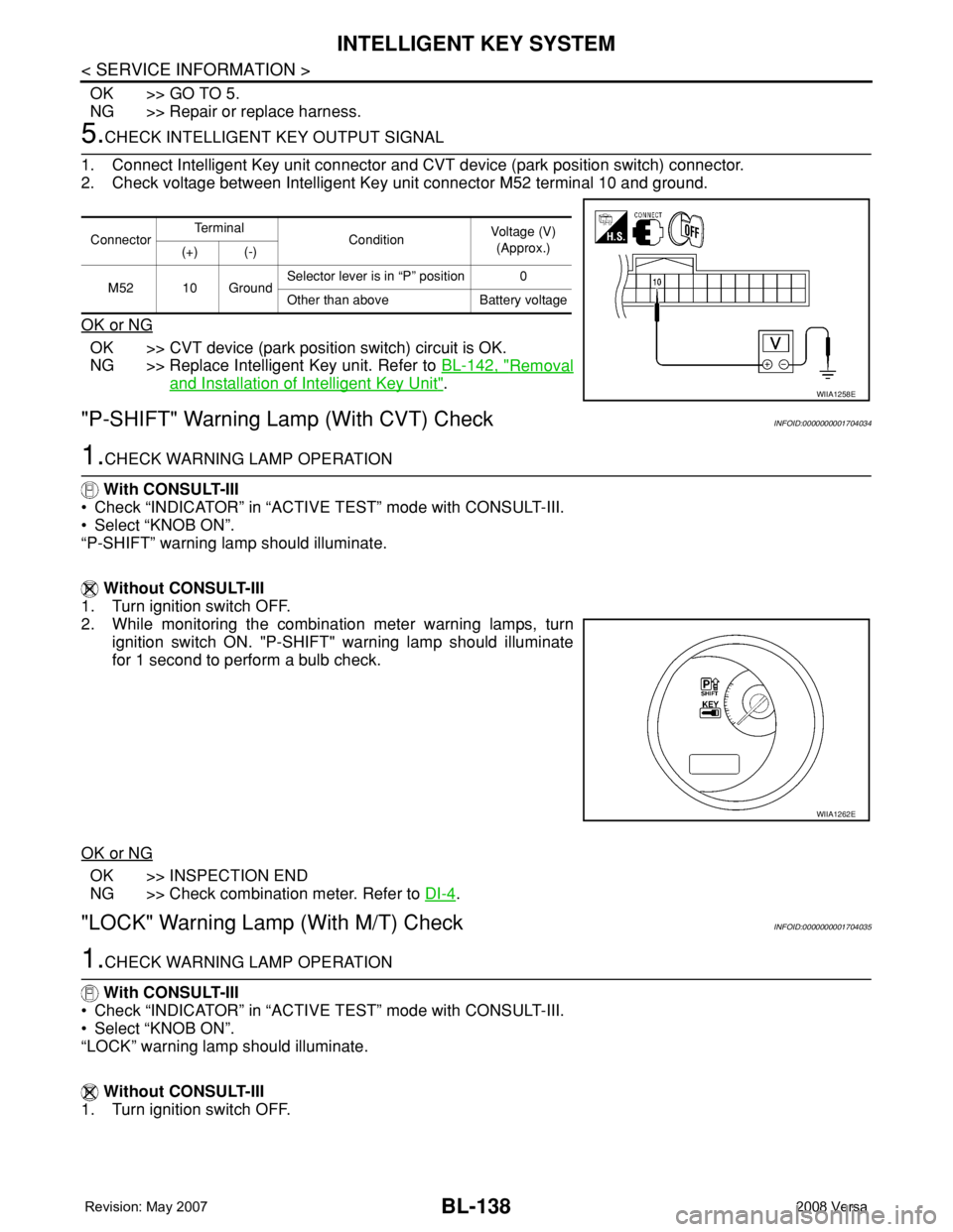
5.CHECK INTELLIGENT KEY OUTPUT SIGNAL
1. Connect Intelligent Key unit connector and CVT device (park position switch) connector.
2. Check voltage between Intelligent Key unit connector M52 terminal 10 and ground.
OK or NG
OK >> CVT device (park position switch) circuit is OK.
NG >> Replace Intelligent Key unit. Refer to BL-142, "
Removal
and Installation of Intelligent Key Unit".
"P-SHIFT" Warning Lamp (With CVT) CheckINFOID:0000000001704034
1.CHECK WARNING LAMP OPERATION
With CONSULT-III
• Check “INDICATOR” in “ACTIVE TEST” mode with CONSULT-III.
• Select “KNOB ON”.
“P-SHIFT” warning lamp should illuminate.
Without CONSULT-III
1. Turn ignition switch OFF.
2. While monitoring the combination meter warning lamps, turn
ignition switch ON. "P-SHIFT" warning lamp should illuminate
for 1 second to perform a bulb check.
OK or NG
OK >> INSPECTION END
NG >> Check combination meter. Refer to DI-4
.
"LOCK" Warning Lamp (With M/T) CheckINFOID:0000000001704035
1.CHECK WARNING LAMP OPERATION
With CONSULT-III
• Check “INDICATOR” in “ACTIVE TEST” mode with CONSULT-III.
• Select “KNOB ON”.
“LOCK” warning lamp should illuminate.
Without CONSULT-III
1. Turn ignition switch OFF.
ConnectorTe r m i n a l
ConditionVoltage (V)
(Approx.)
(+) (-)
M52 10 GroundSelector lever is in “P” position 0
Other than above Battery voltage
WIIA1258E
WIIA1262E
Page 573 of 2771
INTELLIGENT KEY SYSTEM
BL-139
< SERVICE INFORMATION >
C
D
E
F
G
H
J
K
L
MA
B
BL
N
O
P
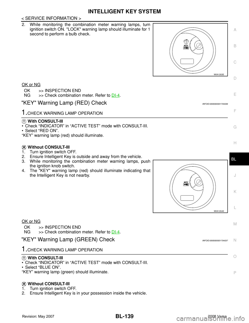
2. While monitoring the combination meter warning lamps, turn
ignition switch ON. "LOCK" warning lamp should illuminate for 1
second to perform a bulb check.
OK or NG
OK >> INSPECTION END
NG >> Check combination meter. Refer to DI-4
.
"KEY" Warning Lamp (RED) CheckINFOID:0000000001704036
1.CHECK WARNING LAMP OPERATION
With CONSULT-III
• Check “INDICATOR” in “ACTIVE TEST” mode with CONSULT-III.
• Select “RED ON”.
“KEY” warning lamp (red) should illuminate.
Without CONSULT-III
1. Turn ignition switch OFF.
2. Ensure Intelligent Key is outside and away from the vehicle.
3. While monitoring the combination meter warning lamps, push
the ignition knob switch.
4. The "KEY" warning lamp (red) should illuminate indicating that
the Intelligent Key is not nearby.
OK or NG
OK >> INSPECTION END
NG >> Check combination meter. Refer to DI-4
.
"KEY" Warning Lamp (GREEN) CheckINFOID:0000000001704037
1.CHECK WARNING LAMP OPERATION
With CONSULT-III
• Check “INDICATOR” in “ACTIVE TEST” mode with CONSULT-III.
• Select “BLUE ON”.
“KEY” warning lamp (green) should illuminate.
Without CONSULT-III
1. Turn ignition switch OFF.
2. Ensure Intelligent Key is in your possession inside the vehicle.
WIIA1263E
WIIA1264E
Page 574 of 2771
BL-140
< SERVICE INFORMATION >
INTELLIGENT KEY SYSTEM
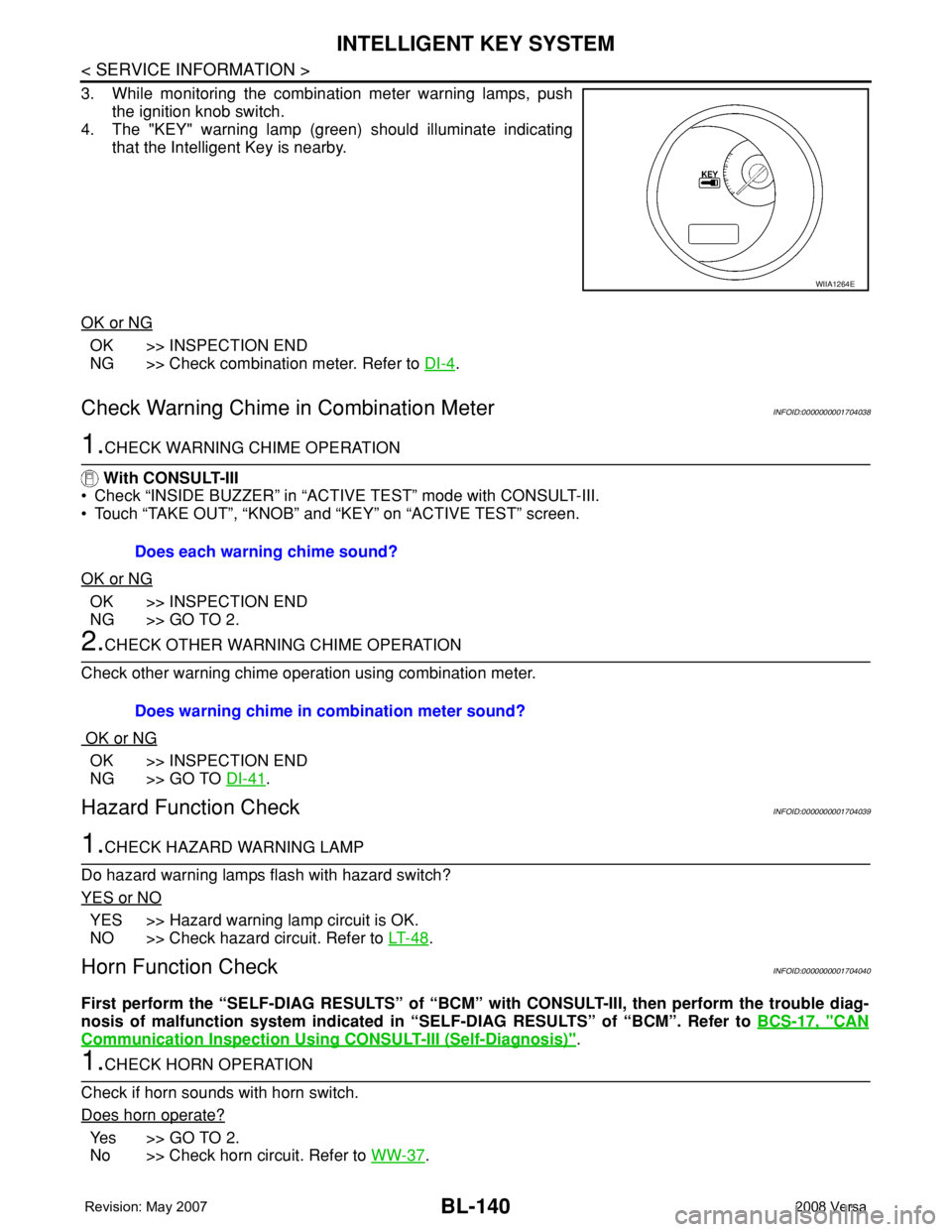
3. While monitoring the combination meter warning lamps, push
the ignition knob switch.
4. The "KEY" warning lamp (green) should illuminate indicating
that the Intelligent Key is nearby.
OK or NG
OK >> INSPECTION END
NG >> Check combination meter. Refer to DI-4
.
Check Warning Chime in Combination MeterINFOID:0000000001704038
1.CHECK WARNING CHIME OPERATION
With CONSULT-III
• Check “INSIDE BUZZER” in “ACTIVE TEST” mode with CONSULT-III.
• Touch “TAKE OUT”, “KNOB” and “KEY” on “ACTIVE TEST” screen.
OK or NG
OK >> INSPECTION END
NG >> GO TO 2.
2.CHECK OTHER WARNING CHIME OPERATION
Check other warning chime operation using combination meter.
OK or NG
OK >> INSPECTION END
NG >> GO TO DI-41
.
Hazard Function CheckINFOID:0000000001704039
1.CHECK HAZARD WARNING LAMP
Do hazard warning lamps flash with hazard switch?
YES or NO
YES >> Hazard warning lamp circuit is OK.
NO >> Check hazard circuit. Refer to LT- 4 8
.
Horn Function CheckINFOID:0000000001704040
First perform the “SELF-DIAG RESULTS” of “BCM” with CONSULT-III, then perform the trouble diag-
nosis of malfunction system indicated in “SELF-DIAG RESULTS” of “BCM”. Refer to BCS-17, "
CAN
Communication Inspection Using CONSULT-III (Self-Diagnosis)".
1.CHECK HORN OPERATION
Check if horn sounds with horn switch.
Does horn operate?
Ye s > > G O T O 2 .
No >> Check horn circuit. Refer to WW-37
.
WIIA1264E
Does each warning chime sound?
Does warning chime in combination meter sound?
Page 621 of 2771
VEHICLE SECURITY (THEFT WARNING) SYSTEM
BL-187
< SERVICE INFORMATION >
C
D
E
F
G
H
J
K
L
MA
B
BL
N
O
P
VEHICLE SECURITY (THEFT WARNING) SYSTEM
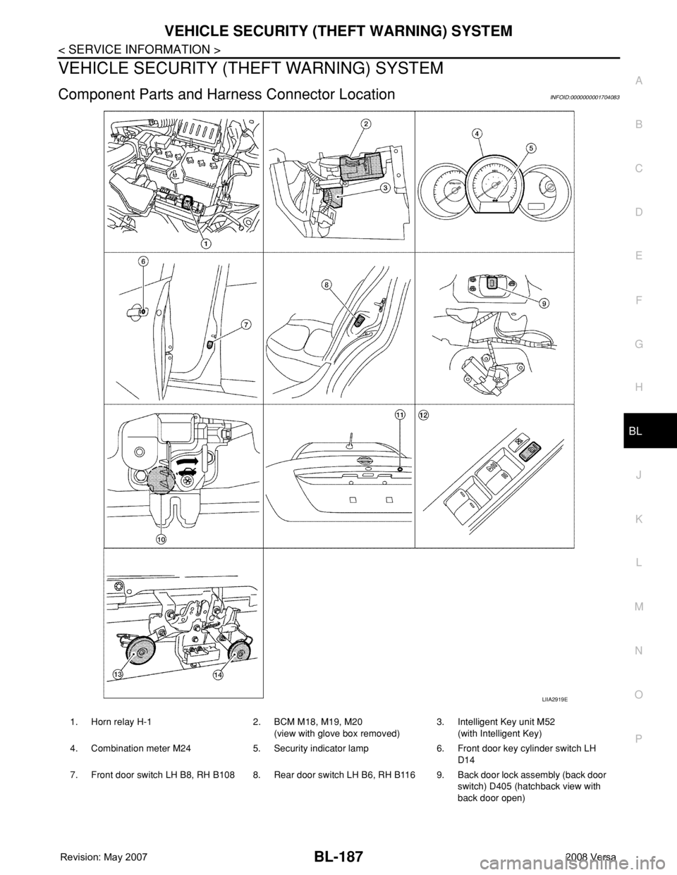
Component Parts and Harness Connector LocationINFOID:0000000001704083
LIIA2919E
1. Horn relay H-1 2. BCM M18, M19, M20
(view with glove box removed)3. Intelligent Key unit M52
(with Intelligent Key)
4. Combination meter M24 5. Security indicator lamp 6. Front door key cylinder switch LH
D14
7. Front door switch LH B8, RH B108 8. Rear door switch LH B6, RH B116 9. Back door lock assembly (back door
switch) D405 (hatchback view with
back door open)