Page 413 of 2771
AV-54
< SERVICE INFORMATION >
TELEPHONE
OK or NG
OK >> GO TO 3.
NG >> Repair harness or connector.
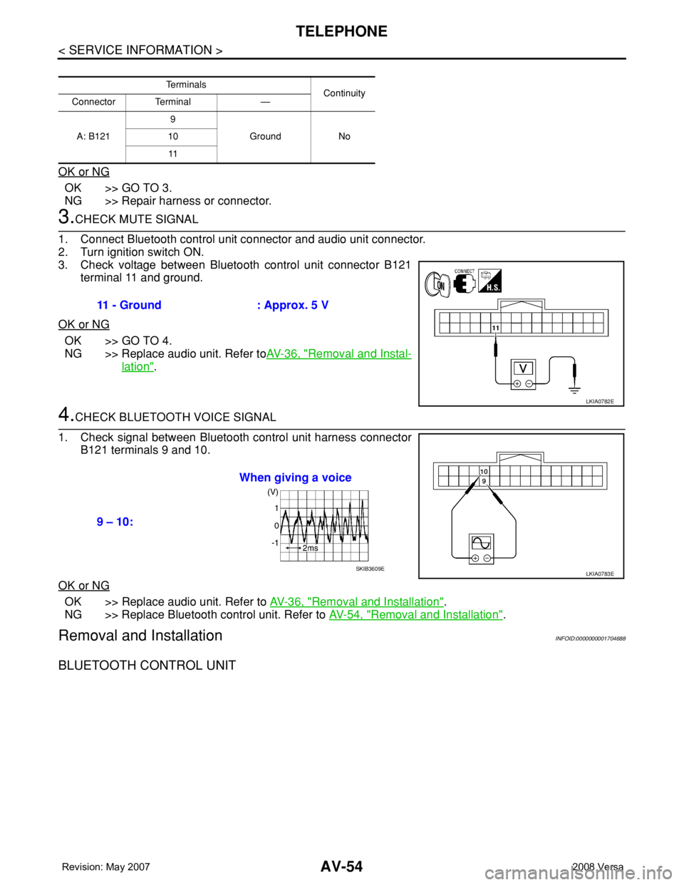
3.CHECK MUTE SIGNAL
1. Connect Bluetooth control unit connector and audio unit connector.
2. Turn ignition switch ON.
3. Check voltage between Bluetooth control unit connector B121
terminal 11 and ground.
OK or NG
OK >> GO TO 4.
NG >> Replace audio unit. Refer toAV-36, "
Removal and Instal-
lation".
4.CHECK BLUETOOTH VOICE SIGNAL
1. Check signal between Bluetooth control unit harness connector
B121 terminals 9 and 10.
OK or NG
OK >> Replace audio unit. Refer to AV-36, "Removal and Installation".
NG >> Replace Bluetooth control unit. Refer to AV-54, "
Removal and Installation".
Removal and InstallationINFOID:0000000001704688
BLUETOOTH CONTROL UNIT
Te r m i n a l s
Continuity
Connector Terminal —
A: B1219
Ground No 10
11
11 - Ground : Approx. 5 V
LKIA0782E
9 – 10:When giving a voice
LKIA0783ESKIB3609E
Page 414 of 2771
TELEPHONE
AV-55
< SERVICE INFORMATION >
C
D
E
F
G
H
I
J
L
MA
B
AV
N
O
P
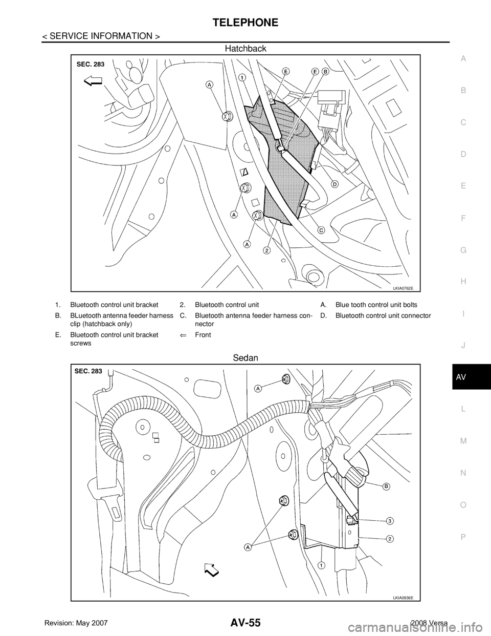
Hatchback
Sedan
LKIA0762E
1. Bluetooth control unit bracket 2. Bluetooth control unit A. Blue tooth control unit bolts
B. BLuetooth antenna feeder harness
clip (hatchback only)C. Bluetooth antenna feeder harness con-
nectorD. Bluetooth control unit connector
E. Bluetooth control unit bracket
screws⇐Front
LKIA0936E
Page 415 of 2771
AV-56
< SERVICE INFORMATION >
TELEPHONE
Removal
1. For hatchback, remove luggage side lower finish (RH). Refer to EI-51, "Removal and Installation".
• Disconnect Bluetooth antenna harness clip.
2. For sedan, remove the trunk room side finisher (RH). Refer to EI-53, "
Removal and Installation".
• Disconnect the Bluetooth antenna harness connector.
3. Disconnect the Bluetooth control unit harness connector.
4. Remove the Bluetooth control unit upper and lower bracket bolts.
5. Unhook the Bluetooth control unit upper and lower brackets and remove Bluetooth control unit.
6. Remove Bluetooth control unit bracket screws and remove the upper and lower brackets from unit.
Installation
Installation is in the reverse order of removal.
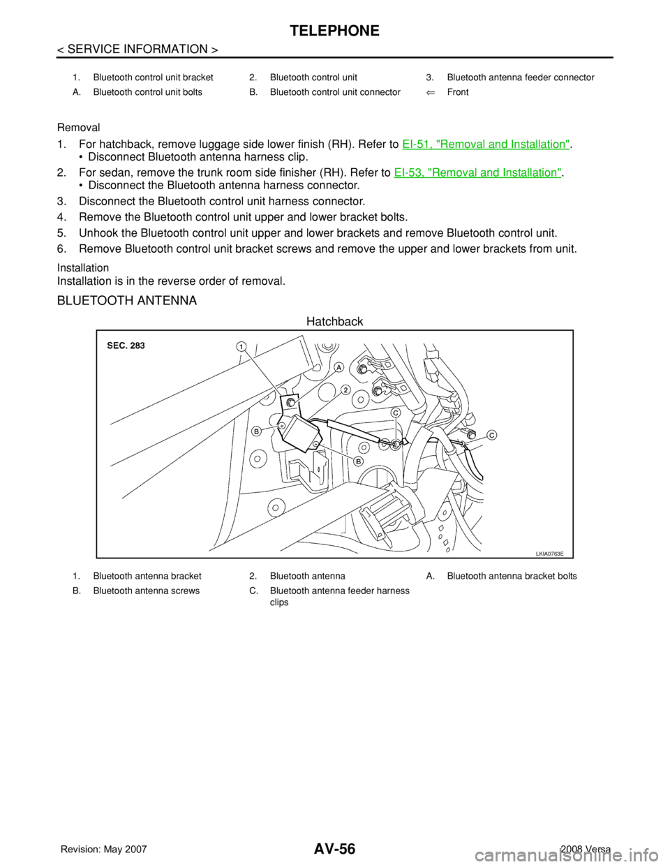
BLUETOOTH ANTENNA
Hatchback
1. Bluetooth control unit bracket 2. Bluetooth control unit 3. Bluetooth antenna feeder connector
A. Bluetooth control unit bolts B. Bluetooth control unit connector⇐Front
LKIA0763E
1. Bluetooth antenna bracket 2. Bluetooth antenna A. Bluetooth antenna bracket bolts
B. Bluetooth antenna screws C. Bluetooth antenna feeder harness
clips
Page 416 of 2771
TELEPHONE
AV-57
< SERVICE INFORMATION >
C
D
E
F
G
H
I
J
L
MA
B
AV
N
O
P
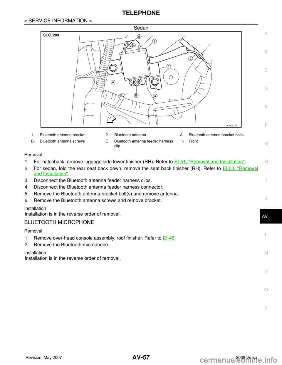
Sedan
Removal
1. For hatchback, remove luggage side lower finisher (RH). Refer to EI-51, "Removal and Installation".
2. For sedan, fold the rear seat back down, remove the seat back finisher (RH). Refer to EI-53, "
Removal
and Installation".
3. Disconnect the Bluetooth antenna feeder harness clips.
4. Disconnect the Bluetooth antenna feeder harness connector.
5. Remove the Bluetooth antenna bracket bolt(s) and remove antenna.
6. Remove the Bluetooth antenna screws and remove bracket.
Installation
Installation is in the reverse order of removal.
BLUETOOTH MICROPHONE
Removal
1. Remove over-head console assembly, roof finisher. Refer to EI-45.
2. Remove the Bluetooth microphone.
Installation
Installation is in the reverse order of removal.
LKIA0937E
1. Bluetooth antenna bracket 2. Bluetooth antenna A. Bluetooth antenna bracket bolts
B. Bluetooth antenna screws C. Bluetooth antenna feeder harness
clip⇒Front
Page 536 of 2771

BL-102
< SERVICE INFORMATION >
INTELLIGENT KEY SYSTEM
* : Sedan
WORK SUPPORT
Te s t i t e m D e s c r i p t i o n
DOOR LOCK/UNLOCKThis test is able to check door lock/unlock operation.
• The all door lock actuators are unlocked when “ALL UNLK” on CONSULT-III screen is touched.
• The all door lock actuators are locked when “LOCK” on CONSULT-III screen is touched.
ANTENNAThis test is able to check Intelligent Key antenna operation.
When the following conditions are met, hazard warning lamps flash.
• Inside key antenna (front console) detects Intelligent Key, when “ROOM ANT1” on CONSULT-
III screen is touched.
• Inside key antenna (instrument panel and rear floor) detects Intelligent Key, when “ROOM
ANT2” on CONSULT-III screen is touched.
• Outside key antenna (driver side) detects Intelligent Key, when “DRIVER ANT” on CONSULT-III
screen is touched.
• Outside key antenna (passenger side) detects Intelligent Key, when “ASSIST ANT” on CON-
SULT-III screen is touched.
• Outside key antenna (rear bumper) detects Intelligent Key, when “BK DOOR ANT” on CON-
SULT-III screen is touched.
OUTSIDE BUZZER(S)
(DRIVER DOOR), (TRUNK)
*This test is able to check Intelligent Key warning buzzer operation.
Intelligent Key warning buzzer sounds when “ON” on CONSULT-III screen is touched.
INSIDE BUZZER
(CHIME)This test is able to check Intelligent Key warning chime (Instrument panel) operation.
• Take away warning chime sounds when “TAKE OUT” on CONSULT-III screen is touched.
• Ignition switch warning chime sounds when “KNOB” on CONSULT-III screen is touched.
• Ignition key warning chime sounds when “KEY” on CONSULT-III screen is touched.
INDICATORThis test is able to check warning lamp operation.
• “KEY” Warning lamp (Green) illuminates when “BLUE ON” on CONSULT-III screen is touched.
• “KEY” Warning lamp (Red) illuminates when “RED ON” on CONSULT-III screen is touched.
• “LOCK” Warning lamp illuminates when “KNOB ON” on CONSULT-III screen is touched.
• “KEY” Warning lamp (Green) flashes when “BLUE IND” on CONSULT-III screen is touched.
• “KEY” Warning lamp (RED) flashes when “BLUE IND” on CONSULT-III screen is touched.
• “P-SHIFT” Warning lamp flashes when “KNOB ON” on CONSULT-III screen is touched.
Monitor item Description
CONFIRM KEY FOB ID It can be checked whether Intelligent Key ID code is registered or not in this mode.
TAKE OUT FROM WINDOW
WARNTake away warning chime (from window) mode can be changed to operate (ON) or not operate
(OFF) with this mode. The operation mode will be changed when “CHANGE SETT” on CONSULT-
III screen is touched.
LOW BAT OF KEY FOB WARNIntelligent Key low battery warning mode can be changed to operate (ON) or not operate (OFF)
with this mode. The operation mode will be changed when “CHANGE SETT” on CONSULT-III
screen is touched.
ANSWER BACK FUNCTIONBuzzer reminder function mode by Intelligent button can be changed to operate (ON) or not oper-
ate (OFF) with this mode. The operation mode will be changed when “CHANGE SETT” on CON-
SULT-III screen is touched.
SELECTIVE UNLOCK FUNC-
TIONSelective unlock function mode can be changed to operate (ON) or not operate (OFF) with this
mode. The operation mode will be changed when “CHANGE SETT” on CONSULT-III screen is
touched.
ANTI KEY LOCK IN FUNCTIONKey reminder function mode can be changed to operate (ON) or not operate (OFF) with this mode.
The operation mode will be changed when “CHANGE SETT” on CONSULT-III screen is touched.
HORN WITH KEYLESS LOCKHorn reminder function mode by Intelligent Key remote control button can be changed to operate
(ON) or not operate (OFF) with this mode. The operation mode will be changed when “CHANGE
SETT” on CONSULT-III screen is touched.
HAZARD ANSWER BACKHazard reminder function mode can be selected from the following with this mode. The operation
mode will be changed when “CHANGE SETT” on CONSULT-III screen is touched.
• LOCK ONLY: Door lock operation only
• UNLOCK ONLY: Door unlock operation only
• LOCK/UNLOCK: Lock/Unlock operation
• OFF: Non-operation
Page 573 of 2771
INTELLIGENT KEY SYSTEM
BL-139
< SERVICE INFORMATION >
C
D
E
F
G
H
J
K
L
MA
B
BL
N
O
P
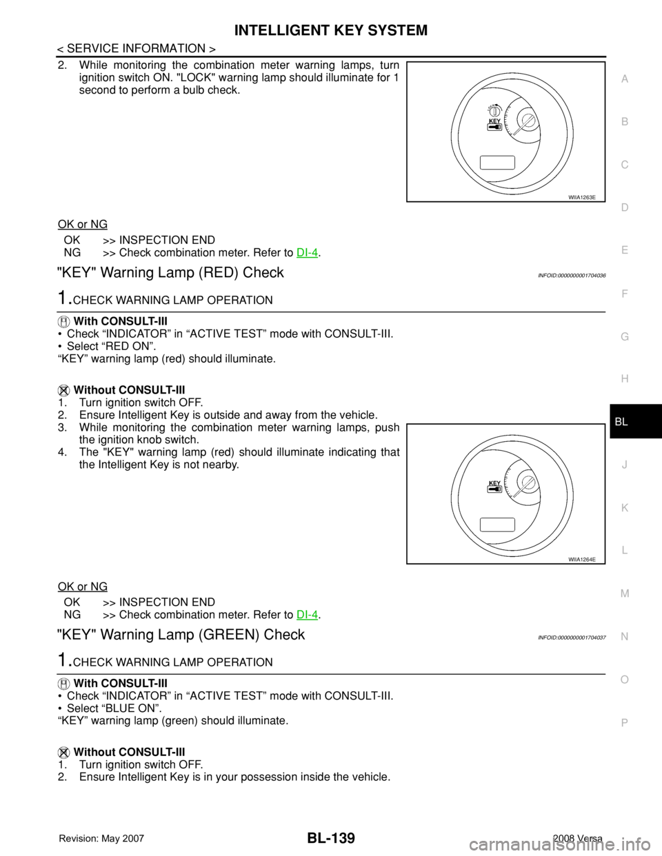
2. While monitoring the combination meter warning lamps, turn
ignition switch ON. "LOCK" warning lamp should illuminate for 1
second to perform a bulb check.
OK or NG
OK >> INSPECTION END
NG >> Check combination meter. Refer to DI-4
.
"KEY" Warning Lamp (RED) CheckINFOID:0000000001704036
1.CHECK WARNING LAMP OPERATION
With CONSULT-III
• Check “INDICATOR” in “ACTIVE TEST” mode with CONSULT-III.
• Select “RED ON”.
“KEY” warning lamp (red) should illuminate.
Without CONSULT-III
1. Turn ignition switch OFF.
2. Ensure Intelligent Key is outside and away from the vehicle.
3. While monitoring the combination meter warning lamps, push
the ignition knob switch.
4. The "KEY" warning lamp (red) should illuminate indicating that
the Intelligent Key is not nearby.
OK or NG
OK >> INSPECTION END
NG >> Check combination meter. Refer to DI-4
.
"KEY" Warning Lamp (GREEN) CheckINFOID:0000000001704037
1.CHECK WARNING LAMP OPERATION
With CONSULT-III
• Check “INDICATOR” in “ACTIVE TEST” mode with CONSULT-III.
• Select “BLUE ON”.
“KEY” warning lamp (green) should illuminate.
Without CONSULT-III
1. Turn ignition switch OFF.
2. Ensure Intelligent Key is in your possession inside the vehicle.
WIIA1263E
WIIA1264E
Page 659 of 2771
BODY REPAIR
BL-225
< SERVICE INFORMATION >
C
D
E
F
G
H
J
K
L
MA
B
BL
N
O
P
BODY REPAIR
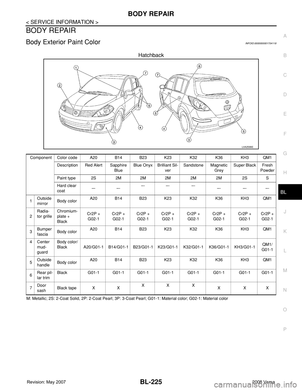
Body Exterior Paint ColorINFOID:0000000001704118
Hatchback
M: Metallic; 2S: 2-Coat Solid, 2P: 2-Coat Pearl; 3P: 3-Coat Pearl; G01-1: Material color; G02-1: Material color
LIIA2599E
Component Color code A20 B14 B23 K23 K32 K36 KH3 QM1
Description Red Alert Sapphire
BlueBlue Onyx Brilliant Sil-
verSandstone Magnetic
GreySuper Black Fresh
Powder
Paint type 2S 2M 2M 2M 2M 2M 2S S
Hard clear
coat–- –-–- –- –-
–- –- –-
1Outside
mirrorBody colorA20 B14 B23 K23 K32 K36 KH3 QM1
2Radia-
tor grilleChromium-
plate +
BlackCr2P +
G02-1Cr2P +
G02-1Cr2P +
G02-1Cr2P +
G02-1Cr2P +
G02-1Cr2P +
G02-1Cr2P +
G02-1Cr2P +
G02-1
3Bumper
fasciaBody colorA20 B14 B23 K23 K32 K36 KH3 QM1
4Center
mud-
guard Body color/
Black A20/G01-1 B14/G01-1 B23/G01-1 K23/G01-1 K32/G01-1 K36/G01-1 KH3/G01-1QM1/
G01-1
5Outside
handleBody colorA20 B14 B23 K23 K32 K36 KH3 QM1
6Rear pil-
lar trimBlack G01-1 G01-1 G01-1 G01-1 G01-1 G01-1 G01-1 G01-1
7Door
sashBlack tape X XXX X
XXX
Page 660 of 2771
BL-226
< SERVICE INFORMATION >
BODY REPAIR
Sedan
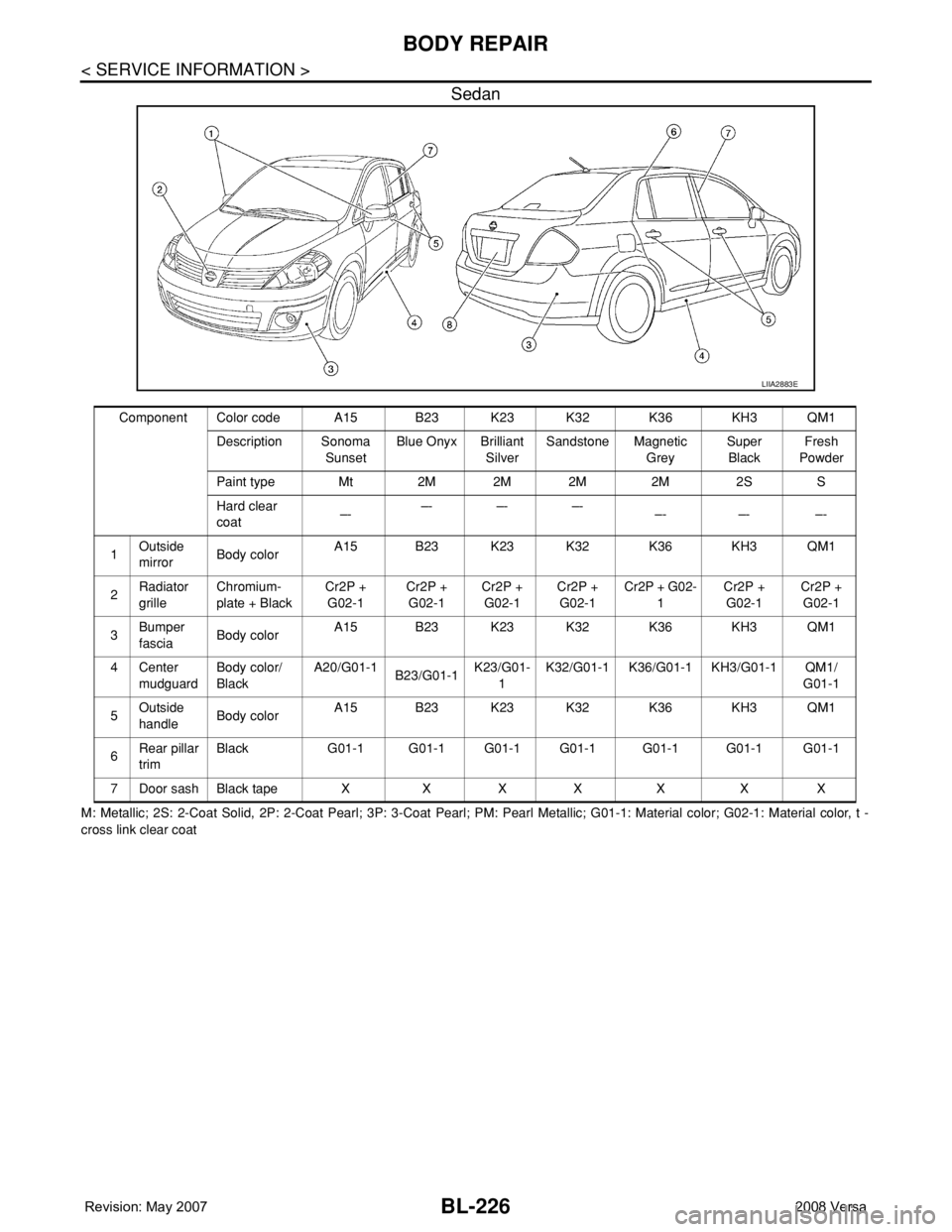
M: Metallic; 2S: 2-Coat Solid, 2P: 2-Coat Pearl; 3P: 3-Coat Pearl; PM: Pearl Metallic; G01-1: Material color; G02-1: Material color, t -
cross link clear coat
LIIA2883E
Component Color code A15 B23 K23 K32 K36 KH3 QM1
Description Sonoma
SunsetBlue Onyx Brilliant
SilverSandstone Magnetic
GreySuper
BlackFresh
Powder
Paint type Mt 2M 2M 2M 2M 2S S
Hard clear
coat–-–- –- –-
–- –- –-
1Outside
mirrorBody colorA15 B23 K23 K32 K36 KH3 QM1
2Radiator
grilleChromium-
plate + BlackCr2P +
G02-1Cr2P +
G02-1Cr2P +
G02-1Cr2P +
G02-1Cr2P + G02-
1Cr2P +
G02-1Cr2P +
G02-1
3Bumper
fasciaBody colorA15 B23 K23 K32 K36 KH3 QM1
4Center
mudguard Body color/
BlackA20/G01-1
B23/G01-1K23/G01-
1K32/G01-1 K36/G01-1 KH3/G01-1 QM1/
G01-1
5Outside
handleBody colorA15 B23 K23 K32 K36 KH3 QM1
6Rear pillar
trimBlack G01-1 G01-1 G01-1 G01-1 G01-1 G01-1 G01-1
7 Door sash Black tape X X X X X X X