2008 NISSAN TIIDA door switch
[x] Cancel search: door switchPage 1982 of 2771

IP-16
< ON-VEHICLE REPAIR >
INSTRUMENT PANEL ASSEMBLY
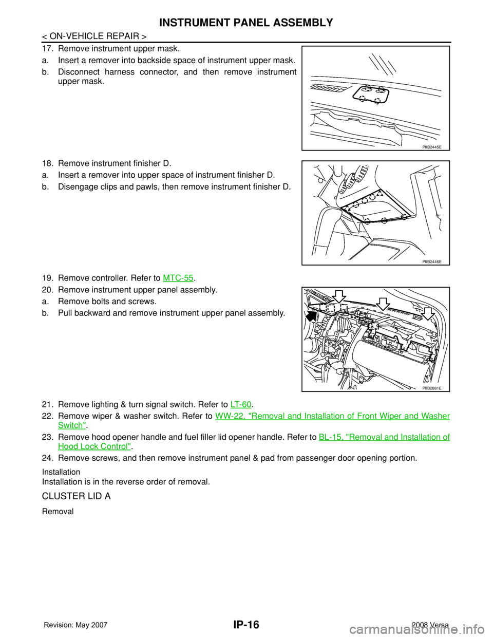
17. Remove instrument upper mask.
a. Insert a remover into backside space of instrument upper mask.
b. Disconnect harness connector, and then remove instrument
upper mask.
18. Remove instrument finisher D.
a. Insert a remover into upper space of instrument finisher D.
b. Disengage clips and pawls, then remove instrument finisher D.
19. Remove controller. Refer to MTC-55
.
20. Remove instrument upper panel assembly.
a. Remove bolts and screws.
b. Pull backward and remove instrument upper panel assembly.
21. Remove lighting & turn signal switch. Refer to LT- 6 0
.
22. Remove wiper & washer switch. Refer to WW-22, "
Removal and Installation of Front Wiper and Washer
Switch".
23. Remove hood opener handle and fuel filler lid opener handle. Refer to BL-15, "
Removal and Installation of
Hood Lock Control".
24. Remove screws, and then remove instrument panel & pad from passenger door opening portion.
Installation
Installation is in the reverse order of removal.
CLUSTER LID A
Removal
PIIB2445E
PIIB2446E
PIIB2881E
Page 2015 of 2771
![NISSAN TIIDA 2008 Service Repair Manual LAN-24
< FUNCTION DIAGNOSIS >[CAN]
CAN COMMUNICATION SYSTEM
Engine coolant temperature signal T R
Engine speed signal T R R
Engine status signal T R
Fuel consumption monitor signal T R
Malfunction ind NISSAN TIIDA 2008 Service Repair Manual LAN-24
< FUNCTION DIAGNOSIS >[CAN]
CAN COMMUNICATION SYSTEM
Engine coolant temperature signal T R
Engine speed signal T R R
Engine status signal T R
Fuel consumption monitor signal T R
Malfunction ind](/manual-img/5/57399/w960_57399-2014.png)
LAN-24
< FUNCTION DIAGNOSIS >[CAN]
CAN COMMUNICATION SYSTEM
Engine coolant temperature signal T R
Engine speed signal T R R
Engine status signal T R
Fuel consumption monitor signal T R
Malfunction indicator lamp signal T R
Wide open throttle position signal T R R
A/C switch signal R T
Blower fan motor switch signal R T
Buzzer output signalTR
TR
Day time running light request signal
*3TR R
Door lock/unlock status signal T R
Door switch signal T R R R
Front wiper request signal T R
High beam request signal T R R
Horn chirp signal T R
Ignition switch signal T R
Low beam request signal T R
Position lights request signal T R R
Rear window defogger switch signal T R
Sleep/wake up signalRT
TRR R
Theft warning horn request signal T R
Tire pressure signal
*4TR
Trunk open/close status signal T R
Turn indicator signal T R
EPS operation signal R T
EPS warning lamp signal T R
Door lock/unlock/trunk open request signal R T
Hazard request signal R T
Ignition knob switch signal R T
KEY warning lamp signal T R
LOCK warning lamp signal T R
Panic alarm request signal R T
Fuel level sensor signal R T
Overdrive control switch signal T R R
P/N range signal T R
Stop lamp switch signal T R R
Vehicle speed signalRRR T
RRRT R
R
*5R*5T*5
ABS warning lamp signal R TSignal name/Connecting unit
ECM
BCM
EPS
I-KEY
M&A
ABS
TCM
*1
TCM
*2
IPDM-E
Page 2149 of 2771

LT-12
< SERVICE INFORMATION >
HEADLAMP (FOR USA)
Note 1: Vehicles without daytime light system may display this item, but cannot monitor it.
ACTIVE TEST
Display Item List
SELF-DIAGNOSTIC RESULTS
Display Item List
CONSULT-III Function (IPDM E/R)INFOID:0000000001704370
CONSULT-III can display each diagnostic item using the diagnostic test modes shown following.
DATA MONITOR
All Items, Main Items, Select Item Menu
LIGHT SW 1ST "ON/OFF"Displays status (lighting switch 1st position: ON/Others: OFF) of lighting switch judged from lighting
switch signal.
PASSING SW "ON/OFF"Displays status (flash-to-pass switch: ON/Others: OFF) of flash-to-pass switch judged from lighting
switch signal.
FR FOG SW "ON/OFF"Displays status (front fog lamp switch: ON/Others: OFF) of front fog lamp switch judged from light-
ing switch signal.
DOOR SW - DR "ON/OFF"Displays status of the front door LH as judged from the front door switch LH signal. (Door is open:
ON/Door is closed: OFF)
DOOR SW - AS "ON/OFF"Displays status of the front door RH as judged from the front door switch RH signal. (Door is open:
ON/Door is closed: OFF)
DOOR SW - RR "ON/OFF"Displays status of the rear door as judged from the rear door switch (RH) signal. (Door is open:
ON/Door is closed: OFF)
DOOR SW - RL "ON/OFF"Displays status of the rear door as judged from the rear door switch (LH) signal. (Door is open: ON/
Door is closed: OFF)
BACK DOOR SW "ON/OFF"Displays status of the back door as judged from the back door switch signal. (Door is open: ON/
Door is closed: OFF)
TURN SIGNAL R "ON/OFF" Displays status (Turn right: ON/Others: OFF) as judged from lighting switch signal.
TURN SIGNAL L "ON/OFF" Displays status (Turn left: ON/Others: OFF) as judged from lighting switch signal.
ENGINE RUN
Note 1"ON/OFF" Displays status (Engine running: ON/Others: OFF) as judged from engine status signal.
PKB SW
Note 1"ON/OFF"Displays status (Parking brake switch: ON/Others: OFF) as judged from parking brake switch sig-
nal. Monitor item Contents
Test item Description
TAIL LAMP Allows tail lamp relay to operate by switching ON-OFF.
HEAD LAMP Allows headlamp relay (HI, LO) to operate by switching ON-OFF.
FR FOG LAMP Allows fog lamp relay to operate by switching ON-OFF.
Monitored item CONSULT-llI display Description
CAN communication CAN communication [U1000] Malfunction is detected in CAN communication.
CAN communication system CAN communication system 1 to 6 [U1000] Malfunction is detected in CAN system.
IPDM E/R diagnostic Mode Description
SELF-DIAG RESULTS Displays IPDM E/R self-diagnosis results.
DATA MONITOR Displays IPDM E/R input/output data in real time.
CAN DIAG SUPPORT MNTR The result of transmit/receive diagnosis of CAN communication can be read.
ACTIVE TEST Operation of electrical loads can be checked by sending drive signal to them.
Page 2197 of 2771

LT-60
< SERVICE INFORMATION >
LIGHTING AND TURN SIGNAL SWITCH
LIGHTING AND TURN SIGNAL SWITCH
Removal and InstallationINFOID:0000000001704430
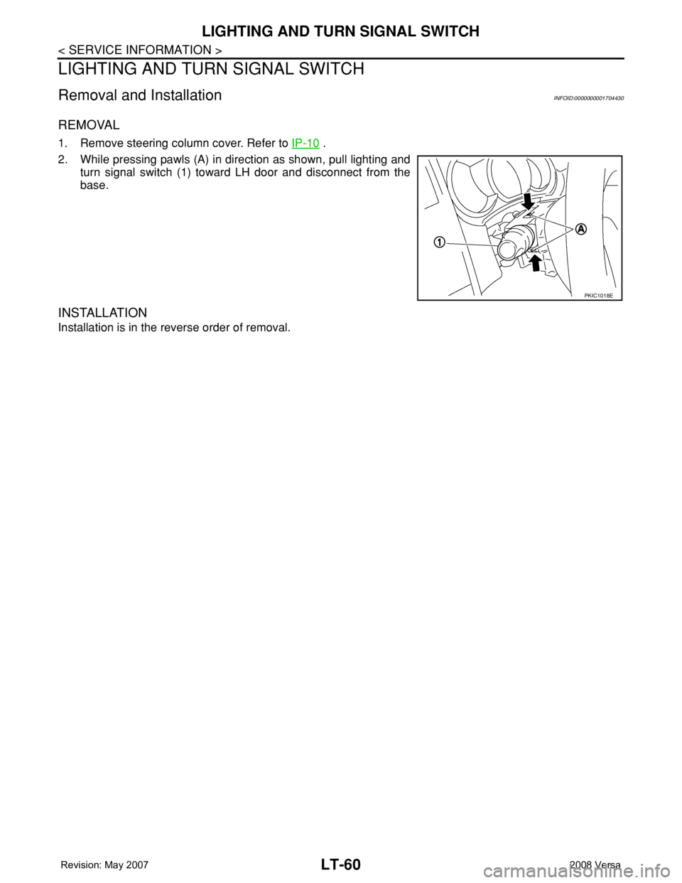
REMOVAL
1. Remove steering column cover. Refer to IP-10 .
2. While pressing pawls (A) in direction as shown, pull lighting and
turn signal switch (1) toward LH door and disconnect from the
base.
INSTALLATION
Installation is in the reverse order of removal.
PKIC1018E
Page 2226 of 2771

INTERIOR ROOM LAMP
LT-89
< SERVICE INFORMATION >
C
D
E
F
G
H
I
J
L
MA
B
LT
N
O
P
INTERIOR ROOM LAMP
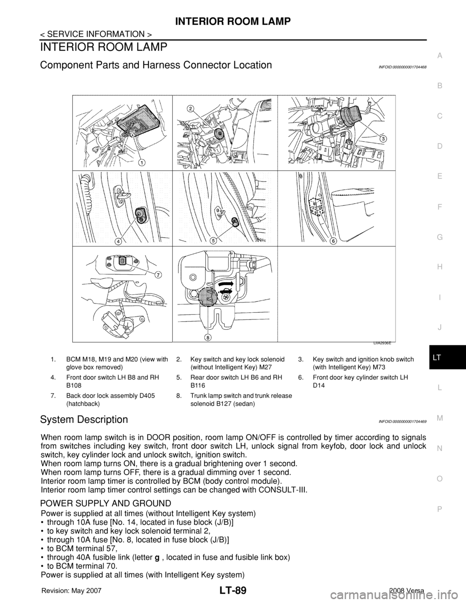
Component Parts and Harness Connector LocationINFOID:0000000001704468
System DescriptionINFOID:0000000001704469
When room lamp switch is in DOOR position, room lamp ON/OFF is controlled by timer according to signals
from switches including key switch, front door switch LH, unlock signal from keyfob, door lock and unlock
switch, key cylinder lock and unlock switch, ignition switch.
When room lamp turns ON, there is a gradual brightening over 1 second.
When room lamp turns OFF, there is a gradual dimming over 1 second.
Interior room lamp timer is controlled by BCM (body control module).
Interior room lamp timer control settings can be changed with CONSULT-III.
POWER SUPPLY AND GROUND
Power is supplied at all times (without Intelligent Key system)
• through 10A fuse [No. 14, located in fuse block (J/B)]
• to key switch and key lock solenoid terminal 2,
• through 10A fuse [No. 8, located in fuse block (J/B)]
• to BCM terminal 57,
• through 40A fusible link (letter g , located in fuse and fusible link box)
• to BCM terminal 70.
Power is supplied at all times (with Intelligent Key system)
1. BCM M18, M19 and M20 (view with
glove box removed)2. Key switch and key lock solenoid
(without Intelligent Key) M273. Key switch and ignition knob switch
(with Intelligent Key) M73
4. Front door switch LH B8 and RH
B1085. Rear door switch LH B6 and RH
B1166. Front door key cylinder switch LH
D14
7. Back door lock assembly D405
(hatchback)8. Trunk lamp switch and trunk release
solenoid B127 (sedan)
LIIA2936E
Page 2227 of 2771

LT-90
< SERVICE INFORMATION >
INTERIOR ROOM LAMP
• through 10A fuse (No. 31, located in fuse and fusible link box)
• to key switch and ignition knob switch terminals 2 and 4,
• through 10A fuse [No. 8, located in fuse block (J/B)]
• to BCM terminal 57,
• through 40A fusible link (letter g , located in fuse and fusible link box)
• to BCM terminal 70.
When key is inserted in the key switch and key lock solenoid, power is supplied (without Intelligent Key sys-
tem)
• through key switch and key lock solenoid terminal 1
• to BCM terminal 37.
When key is inserted in the key switch and ignition knob switch, power is supplied (with Intelligent Key system)
• through key switch and ignition knob switch terminal 1
• to BCM terminal 37.
When ignition knob switch is pushed, power is supplied (with Intelligent Key system)
• through key switch and ignition knob switch terminal 3
• to Intelligent Key unit terminal 27.
With the ignition switch in the ON or START position, power is supplied
• through 10A fuse [No. 6, located in fuse block (J/B)]
• to BCM terminal 38.
Ground is supplied
• to BCM terminal 67
• through grounds M57 and M61.
When front door LH is opened, ground is supplied
• to BCM terminal 47
• through front door switch LH terminal 2
• through case ground of front door switch LH.
When front door RH is opened, ground is supplied
• to BCM terminal 12
• through front door switch RH terminal 2
• through case ground of front door switch RH.
When rear door LH is opened, ground is supplied
• to BCM terminal 48
• through rear door switch LH terminal 1
• through case ground of rear door switch LH.
When rear door RH is opened, ground is supplied
• to BCM terminal 13
• through rear door switch RH terminal 1
• through case ground of rear door switch RH.
When back door (hatchback) is opened, ground is supplied
• to BCM terminal 43
• through back door lock assembly (back door switch) terminal 3
• through back door lock assembly (back door switch) terminal 4
• through grounds B117, B132 and D402.
When trunk lid (sedan) is opened, ground is supplied
• to BCM terminal 42
• through trunk lamp switch and trunk release solenoid terminal 3
• through trunk lamp switch and trunk release solenoid terminal 1
• through grounds B117 and B132.
When front door LH is unlocked by front door key cylinder switch LH, the BCM receives a ground signal
• to BCM terminal 7
• through front door key cylinder switch LH terminal 3
• through front door key cylinder switch LH terminal 2
• through grounds M57 and M61.
When a signal, or combination of signals is received by BCM, ground is supplied
• to room lamp terminal 2
• through map lamp terminals 5 and 2 (with map lamp)
• through BCM terminal 63.
With power and ground supplied, the interior room lamp illuminates.
SWITCH OPERATION
When map lamp switch is ON (with map lamp), ground is supplied
• through grounds M57 and M61.
Page 2228 of 2771

INTERIOR ROOM LAMP
LT-91
< SERVICE INFORMATION >
C
D
E
F
G
H
I
J
L
MA
B
LT
N
O
P
• to map lamp terminal 1
Power is supplied
• through BCM terminal 56
• to map lamp terminal 4.
When interior room lamp switch is ON, ground is supplied
• to interior room lamp terminal 1
• through map lamp (with map lamp) terminal 7
• through map lamp (with map lamp) terminal 1
• through grounds M57 and M61.
Power is supplied
• through BCM terminal 56
• through map lamp (with map lamp) terminal 4
• through map lamp (with map lamp) terminal 6
• to room lamp terminal 3.
INTERIOR ROOM LAMP TIMER OPERATION
Without Intelligent Key System
When room lamp switch is in DOOR position, and when all conditions below are met, BCM performs timer
control (maximum 30 seconds) for room lamp ON/OFF.
In addition, when the interior room lamp turns ON or OFF there is gradual brightening or dimming over 1 sec-
ond.
Power is supplied
• through 10A fuse [No. 14, located in fuse block (J/B)]
• to key switch and key lock solenoid terminal 2.
When the key is removed from ignition key cylinder (key switch OFF), power will not be supplied to BCM termi-
nal 37.
When front door key cylinder switch LH is unlocked, ground is supplied
• to BCM terminal 7
• through front door key cylinder switch LH terminal 3
• through front door key cylinder switch LH terminal 2
• through grounds M57 and M61.
At the time that front door LH is opened, BCM detects that front door LH is unlocked. It determines that interior
room lamp timer operation condition is met, and turns the room lamp ON for 30 seconds.
When key is in ignition key cylinder (key switch ON),
Power is supplied
• through key switch and key lock solenoid terminal 1
• to BCM terminal 37.
When key is removed from key switch and key lock solenoid (key switch OFF), the power supply to BCM ter-
minal 37 is terminated. BCM detects that key has been removed, determines that interior room lamp timer
conditions are met, and turns the room lamp ON for 30 seconds.
When front door LH opens → closes, and the key is not inserted in the key switch and key lock solenoid (key
switch OFF), voltage at BCM terminal 47 changes between 0V (door open) → 12V (door closed). The BCM
determines that conditions for room lamp operation are met and turns the room lamp ON for 30 seconds.
Interior room lamp timer control is canceled under the following conditions:
• Front door LH is locked (locked front door key cylinder switch LH).
• Front door LH is opened (front door switch LH).
• Ignition switch ON.
With Intelligent Key System
When the room lamp switch is in DOOR position, and when all conditions below are met, BCM performs timer
control (maximum 30 second) for room lamp ON/OFF.
In addition, when interior room lamp turns ON or OFF there is gradual brightening or dimming over 1 second.
Power is supplied
• through 10A fuse (No. 31, located in fuse and fusible link box)
• to key switch and ignition knob switch terminals 2 and 4.
When key is removed from ignition key cylinder (key switch OFF), power will not be supplied to BCM terminal
37.
When the ignition knob switch is released, power will not be supplied to Intelligent Key unit terminal 27.
When front door key cylinder switch LH is unlocked, ground is supplied
• to BCM terminal 7
• through front door key cylinder switch LH terminal 3
Page 2229 of 2771

LT-92
< SERVICE INFORMATION >
INTERIOR ROOM LAMP
• through front door key cylinder switch LH terminal 2
• through grounds M57 and M61.
At the time the front door LH is opened, the BCM detects the front door LH is unlocked. It determines that the
interior room lamp timer operation conditions are met, and interior room lamp ON for 30 seconds.
When the key is in ignition key cylinder (key switch ON), or ignition knob switch is pushed, power is supplied
• through key switch and ignition knob switch terminal 1
• to BCM terminal 37, or
• through key switch and ignition knob switch terminal 3
• to Intelligent Key unit terminal 27.
When the key is removed from key switch (key switch OFF), power supply to BCM terminal 37 is terminated.
When the ignition knob switch is released, power supply to intelligent key unit is terminated. The BCM detects
that the key has been removed, determines that interior room lamp timer conditions are met, and turns room
lamp ON for 30 seconds.
When the front door LH opens → closes, and key is not inserted in key switch (or ignition knob switch is
released), BCM terminal 47 changes between 0V (door open) → 12V (door closed). BCM determines that
conditions for room lamp operation are met, and turns room lamp ON for 30 seconds.
Interior room lamp timer control is canceled under the following conditions:
• Front door LH is locked (with keyfob or front door key cylinder switch LH).
• Front door LH is opened (front door switch LH).
• Ignition switch ON.
INTERIOR LAMP BATTERY SAVER CONTROL
If an interior room lamp is left ON, it will not be turned OFF even when door is closed.
BCM turns off interior lamp automatically to save battery 30 minutes after ignition switch is turned off.
After lamps are turned OFF by the battery saver system, the lamps illuminate again when
• front door key cylinder switch LH is locked or unlocked
• door is opened or closed
• key is removed from ignition key cylinder or inserted in ignition key cylinder, or the ignition knob switch is
pushed or released.
Interior lamp battery saver control time period can be changed by the function setting of CONSULT-III.