Page 1655 of 2771
EI-32
< ON-VEHICLE REPAIR >
DOOR FINISHER
DOOR FINISHER
Removal and InstallationINFOID:0000000001704233
FRONT DOOR
Removal
1. Open front door and front door window.
2. Disconnect the negative and positive battery cables.
3. Release the front door inside handle escutcheon pawls, then
slide the escutcheon rearward to remove from front door fin-
isher.
1. Power window and door lock/unlock
switch finisher2. Front door finisher 3. Inside handle escutcheon
Clip C101
LIIA2572E
PIIB6040E
Page 1656 of 2771
DOOR FINISHER
EI-33
< ON-VEHICLE REPAIR >
C
D
E
F
G
H
J
K
L
MA
B
EI
N
O
P
4. Insert a trim stick (A) or suitable tool into back edge of front door
power window and door lock/unlock switch finisher. Lift upward
to release the clips and remove.
5. Disconnect front door power window and door lock/unlock
switch harness connector.
6. Remove the (2) front door finisher screws.
7. Release the clips, then lift front door finisher upward to remove it
from door body panel.
Installation
Installation is in the reverse order of removal.
REAR DOOR
WIIA1237E
PIIB6042E
SIIA0810E
Page 1657 of 2771
EI-34
< ON-VEHICLE REPAIR >
DOOR FINISHER
Removal
1. Open rear door and rear door window.
2. Disconnect the negative and positive battery cables.
3. Release the rear door inside handle escutcheon pawls, then
slide the escutcheon rearward to remove from rear door finisher.
4. Insert a trim stick (A), or suitable tool into back edge of rear door
power window switch finisher. Lift upward to release the clips
and remove.
5. Disconnect rear door power window switch harness connector.
6. Remove rear door finisher screw.
1. Rear power window switch finisher 2. Rear door finisher 3. Inside handle escutcheon
Clip C101
LIIA2573E
PIIB6040E
WIIA1238E
Page 1869 of 2771
GI-18
< SERVICE INFORMATION >
HOW TO USE THIS MANUAL
• Letter designations next to test meter probe indicate harness (con-
nector) wire color.
• Connector numbers in a single circle M33 indicate harness con-
nectors.
Component Indication
Connector numbers in a double circle F211 indicate component connectors.
Switch Positions
Switches are shown in wiring diagrams as if the vehicle is in the “normal” condition.
A vehicle is in the “normal” condition when:
• ignition switch is “OFF”,
• doors, hood and trunk lid/back door are closed,
• pedals are not depressed, and
• parking brake is released.
Detectable Lines and Non-Detectable Lines
In some wiring diagrams, two kinds of lines, representing wires, with different weight are used.
AGI070
SGI860
Page 1902 of 2771

GW-1
BODY
C
D
E
F
G
H
J
K
L
M
SECTION GW
A
B
GW
N
O
P
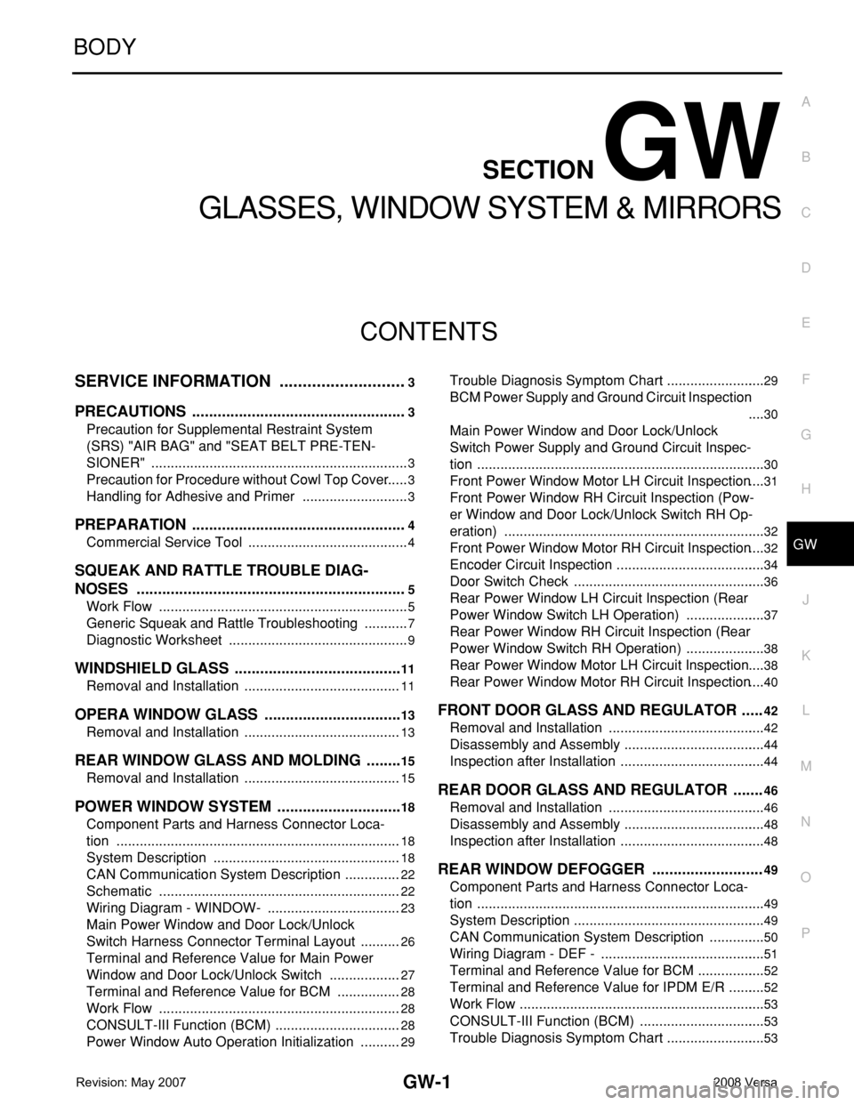
CONTENTS
GLASSES, WINDOW SYSTEM & MIRRORS
SERVICE INFORMATION ............................3
PRECAUTIONS ...................................................3
Precaution for Supplemental Restraint System
(SRS) "AIR BAG" and "SEAT BELT PRE-TEN-
SIONER" ...................................................................
3
Precaution for Procedure without Cowl Top Cover ......3
Handling for Adhesive and Primer ............................3
PREPARATION ...................................................4
Commercial Service Tool ..........................................4
SQUEAK AND RATTLE TROUBLE DIAG-
NOSES ................................................................
5
Work Flow .................................................................5
Generic Squeak and Rattle Troubleshooting ............7
Diagnostic Worksheet ...............................................9
WINDSHIELD GLASS ........................................11
Removal and Installation .........................................11
OPERA WINDOW GLASS .................................13
Removal and Installation .........................................13
REAR WINDOW GLASS AND MOLDING .........15
Removal and Installation .........................................15
POWER WINDOW SYSTEM ..............................18
Component Parts and Harness Connector Loca-
tion ..........................................................................
18
System Description .................................................18
CAN Communication System Description ...............22
Schematic ...............................................................22
Wiring Diagram - WINDOW- ...................................23
Main Power Window and Door Lock/Unlock
Switch Harness Connector Terminal Layout ...........
26
Terminal and Reference Value for Main Power
Window and Door Lock/Unlock Switch ...................
27
Terminal and Reference Value for BCM .................28
Work Flow ...............................................................28
CONSULT-III Function (BCM) .................................28
Power Window Auto Operation Initialization ...........29
Trouble Diagnosis Symptom Chart ..........................29
BCM Power Supply and Ground Circuit Inspection
....
30
Main Power Window and Door Lock/Unlock
Switch Power Supply and Ground Circuit Inspec-
tion ...........................................................................
30
Front Power Window Motor LH Circuit Inspection ....31
Front Power Window RH Circuit Inspection (Pow-
er Window and Door Lock/Unlock Switch RH Op-
eration) ....................................................................
32
Front Power Window Motor RH Circuit Inspection ....32
Encoder Circuit Inspection .......................................34
Door Switch Check ..................................................36
Rear Power Window LH Circuit Inspection (Rear
Power Window Switch LH Operation) .....................
37
Rear Power Window RH Circuit Inspection (Rear
Power Window Switch RH Operation) .....................
38
Rear Power Window Motor LH Circuit Inspection ....38
Rear Power Window Motor RH Circuit Inspection ....40
FRONT DOOR GLASS AND REGULATOR .....42
Removal and Installation .........................................42
Disassembly and Assembly .....................................44
Inspection after Installation ......................................44
REAR DOOR GLASS AND REGULATOR .......46
Removal and Installation .........................................46
Disassembly and Assembly .....................................48
Inspection after Installation ......................................48
REAR WINDOW DEFOGGER ..........................49
Component Parts and Harness Connector Loca-
tion ...........................................................................
49
System Description ..................................................49
CAN Communication System Description ...............50
Wiring Diagram - DEF - ...........................................51
Terminal and Reference Value for BCM ..................52
Terminal and Reference Value for IPDM E/R ..........52
Work Flow ................................................................53
CONSULT-III Function (BCM) .................................53
Trouble Diagnosis Symptom Chart ..........................53
Page 1903 of 2771
GW-2
BCM Power Supply and Ground Circuit Inspection
...
54
Rear Window Defogger Switch Circuit Inspection ...54
Rear Window Defogger Circuit Inspection ..............55
Door Mirror Defogger Circuit Inspection .................58
Filament Check .......................................................59
Filament Repair ......................................................60
DOOR MIRROR .................................................62
Wiring Diagram - MIRROR - ...................................62
Removal and Installation .........................................63
Disassembly and Assembly ....................................63
INSIDE MIRROR ................................................65
Removal and Installation .........................................65
Page 1919 of 2771
GW-18
< SERVICE INFORMATION >
POWER WINDOW SYSTEM
POWER WINDOW SYSTEM
Component Parts and Harness Connector LocationINFOID:0000000001704138
System DescriptionINFOID:0000000001704139
Power is supplied at all times
• through 40A fusible link (letter g , located in the fuse and fusible link box)
• to BCM terminal 70.
With ignition switch in ON or START position, power is supplied
• through 10A fuse [No. 6, located in the fuse block (J/B)]
• to BCM terminal 38
1. Main power window and door lock/
unlock switch D7, D82. Power window and door lock/unlock
switch RH D1053. Rear power window switch LH D203,
RH D303
4. BCM M18, M19, M20 (view with
glove box removed)5. Front power window motor LH D9,
RH D1046. Rear power window motor LH D204,
RH D304
7. Front door switch LH B8, RH B108
LIIA2529E
Page 1920 of 2771

POWER WINDOW SYSTEM
GW-19
< SERVICE INFORMATION >
C
D
E
F
G
H
J
K
L
MA
B
GW
N
O
P
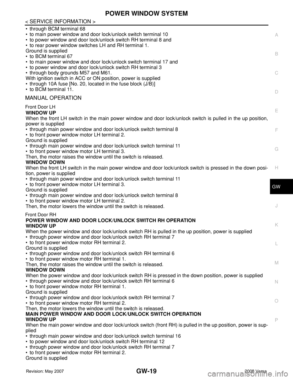
• through BCM terminal 68
• to main power window and door lock/unlock switch terminal 10
• to power window and door lock/unlock switch RH terminal 8 and
• to rear power window switches LH and RH terminal 1.
Ground is supplied
• to BCM terminal 67
• to main power window and door lock/unlock switch terminal 17 and
• to power window and door lock/unlock switch RH terminal 3
• through body grounds M57 and M61.
With ignition switch in ACC or ON position, power is supplied
• through 10A fuse [No. 20, located in the fuse block (J/B)]
• to BCM terminal 11.
MANUAL OPERATION
Front Door LH
WINDOW UP
When the front LH switch in the main power window and door lock/unlock switch is pulled in the up position,
power is supplied
• through main power window and door lock/unlock switch terminal 8
• to front power window motor LH terminal 2.
Ground is supplied
• through main power window and door lock/unlock switch terminal 11
• to front power window motor LH terminal 3.
Then, the motor raises the window until the switch is released.
WINDOW DOWN
When the front LH switch in the main power window and door lock/unlock switch is pressed in the down posi-
tion, power is supplied
• through main power window and door lock/unlock switch terminal 11
• to front power window motor LH terminal 3.
Ground is supplied
• through main power window and door lock/unlock switch terminal 8
• to front power window motor LH terminal 2.
Then, the motor lowers the window until the switch is released.
Front Door RH
POWER WINDOW AND DOOR LOCK/UNLOCK SWITCH RH OPERATION
WINDOW UP
When the power window and door lock/unlock switch RH is pulled in the up position, power is supplied
• through power window and door lock/unlock switch RH terminal 7
• to front power window motor RH terminal 2.
Ground is supplied
• through power window and door lock/unlock switch RH terminal 6
• to front power window motor RH terminal 1.
Then, the motor raises the window until the switch is released.
WINDOW DOWN
When the power window and door lock/unlock switch RH is pressed in the down position, power is supplied
• through power window and door lock/unlock switch RH terminal 6
• to front power window motor RH terminal 1.
Ground is supplied
• through power window and door lock/unlock switch RH terminal 7
• to front power window motor RH terminal 2.
Then, the motor lowers the window until the switch is released.
MAIN POWER WINDOW AND DOOR LOCK/UNLOCK SWITCH OPERATION
WINDOW UP
When the main power window and door lock/unlock switch (front RH) is pulled in the up position, power is sup-
plied
• through main power window and door lock/unlock switch terminal 16
• to power window and door lock/unlock switch RH terminal 12
• through power window and door lock/unlock switch RH terminal 7
• to front power window motor RH terminal 2.
Ground is supplied