Page 325 of 2771
REPAIR FOR COMPONENT PARTS
AT-313
< SERVICE INFORMATION >
D
E
F
G
H
I
J
K
L
MA
B
AT
N
O
P
11. Push in OD servo piston assembly using a puller A (commercial
service tool) and a suitable drift B, and install snap ring (1) to
transaxle case using a flat-bladed screwdriver C.
Final DriveINFOID:0000000001703390
COMPONENTS
DISASSEMBLY
1. Remove final gear (1) from differential case (2).
SCIA7050E
1. Pinion mate gear 2. Pinion mate gear thrust washer 3. Pinion mate shaft
4. Lock pin 5. Side gear 6. Side gear thrust washer
7. Differential side bearing 8. Speedometer drive gear 9. Differential case
10. Final gear 11. Differential side bearing 12. Differential side bearing adjusting
shim
Refer to GI section to make sure icons (symbol marks) in the figure. Refer to GI-8, "
Component".
SCIA7962E
SCIA8003E
Page 326 of 2771
AT-314
< SERVICE INFORMATION >
REPAIR FOR COMPONENT PARTS
2. Press out differential side bearings.
CAUTION:
Be careful not to mix up the right and left bearings.
3. Remove speedometer drive gear from differential case.
4. Drive out lock pin from differential case (1) using Tool (A).
5. Draw out pinion mate shaft.
6. Remove pinion mate gears, pinion mate gear thrust washers,
side gears and side gear thrust washers.
INSPECTION
Gears, Washers, Pinion Mate Shaft and Differential Case
Tool number: ST3306S001 (J-22888-D)
SAT312D
SAT313D
Tool number: KV32101000 (J-25689-A)
SCIA7034E
SAT316D
Page 328 of 2771

AT-316
< SERVICE INFORMATION >
REPAIR FOR COMPONENT PARTS
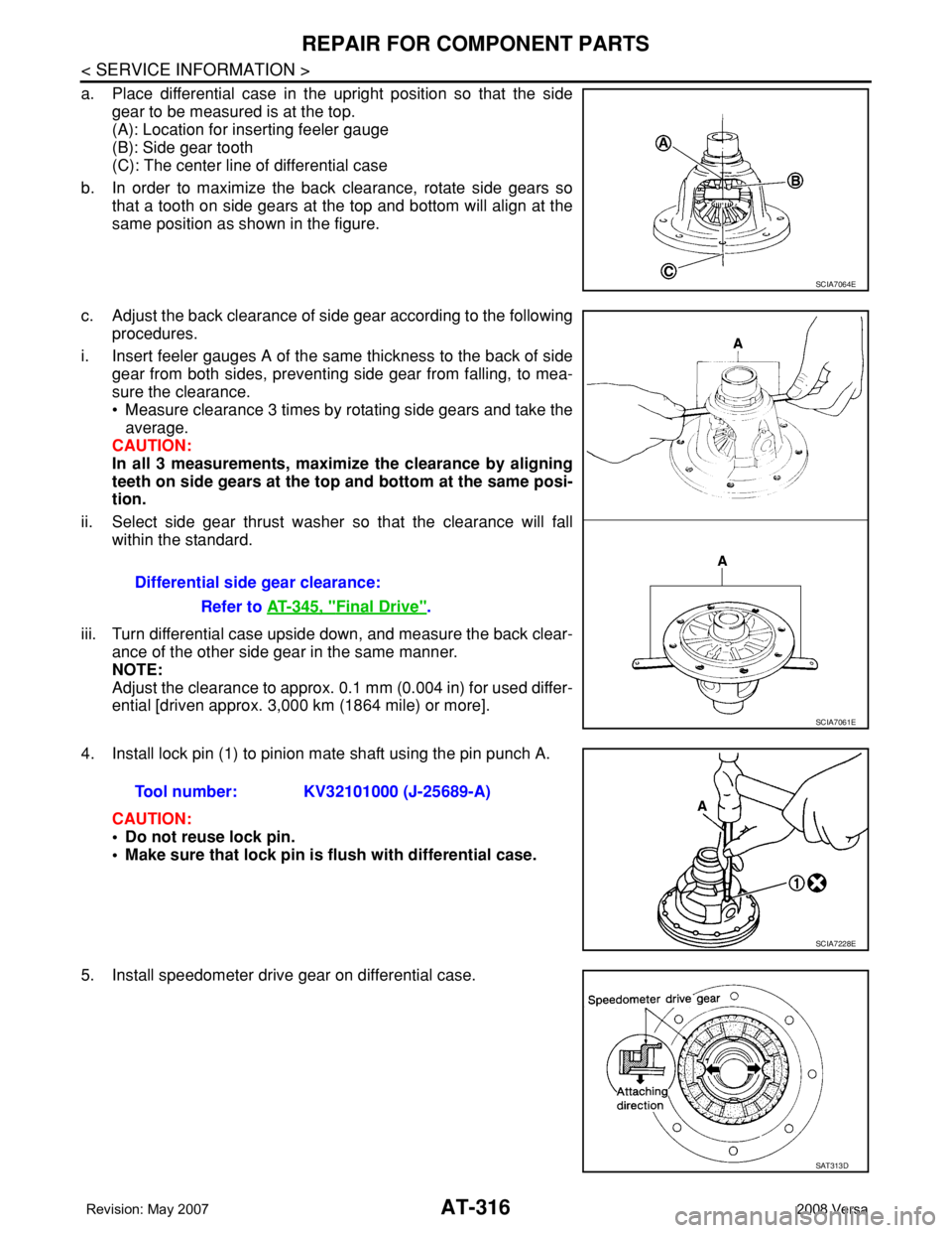
a. Place differential case in the upright position so that the side
gear to be measured is at the top.
(A): Location for inserting feeler gauge
(B): Side gear tooth
(C): The center line of differential case
b. In order to maximize the back clearance, rotate side gears so
that a tooth on side gears at the top and bottom will align at the
same position as shown in the figure.
c. Adjust the back clearance of side gear according to the following
procedures.
i. Insert feeler gauges A of the same thickness to the back of side
gear from both sides, preventing side gear from falling, to mea-
sure the clearance.
• Measure clearance 3 times by rotating side gears and take the
average.
CAUTION:
In all 3 measurements, maximize the clearance by aligning
teeth on side gears at the top and bottom at the same posi-
tion.
ii. Select side gear thrust washer so that the clearance will fall
within the standard.
iii. Turn differential case upside down, and measure the back clear-
ance of the other side gear in the same manner.
NOTE:
Adjust the clearance to approx. 0.1 mm (0.004 in) for used differ-
ential [driven approx. 3,000 km (1864 mile) or more].
4. Install lock pin (1) to pinion mate shaft using the pin punch A.
CAUTION:
• Do not reuse lock pin.
• Make sure that lock pin is flush with differential case.
5. Install speedometer drive gear on differential case.
SCIA7064E
Differential side gear clearance:
Refer to AT-345, "
Final Drive".
SCIA7061E
Tool number: KV32101000 (J-25689-A)
SCIA7228E
SAT313D
Page 348 of 2771
AT-336
< SERVICE INFORMATION >
ASSEMBLY
18. Install O-ring on differential oil port of transaxle case.
19. Apply locking sealant (loctite #518) to transaxle case as shown
in the figure.
: Inside of transaxle case
CAUTION:
Completely remove all moisture, oil and old sealant, etc.
from the transaxle case and converter housing mating sur-
faces.
20. Install converter housing on transaxle case.
21. Install bracket on converter housing.
22. Tighten converter housing fitting bolts (1) and (2) to the specified
torque. Refer to AT-230, "
Component".
23. Install plug or speedometer pinion according to the following
procedures.
a. With ABS
i. Install O-ring (3) to plug (1).
ii. Install plug (1) to converter housing (2).
: Bolt (1)
SCIA3281E
“A”: 3 - 5 mm (0.12 - 0.20 in)
“B”: 8 mm (0.31 in) R
“C”: 1.5 mm (0.059 in) dia.
“D”: 4 mm (0.16 in)
SCIA7089E
Bolt 1 2
Bolt length
[mm (in)]
32.8 (1.291) 40 (1.57)
Number of bolts 10 10
SCIA7970E
SCIA7747E
Page 349 of 2771
ASSEMBLY
AT-337
< SERVICE INFORMATION >
D
E
F
G
H
I
J
K
L
MA
B
AT
N
O
P
b. Without ABS
i. Install O-ring (3) to speedometer pinion (1).
ii. Install speedometer pinion (1) to converter housing (2).
: Bolt (1)
24. Tighten plug or speedometer pinion fitting bolt to the specified torque. Refer to AT-230, "
Component".
25. Install accumulator pistons.
a. Install O-rings (1) on servo release accumulator piston (2) and
N-D accumulator piston (3). Refer to AT-343, "
Accumulator".
b. Install return springs (1), servo release accumulator piston (2)
and N-D accumulator piston (3) into transaxle case (4). Refer to
AT-343, "
Accumulator".
26. Install lip seals (1) for band servo oil holes on transaxle case.
27. Install control valve assembly on transaxle case.
a. Install O-ring on terminal body.
CAUTION:
• Do not reuse O-ring.
• Apply ATF to O-ring.
SCIA7462E
SCIA6033J
SCIA6042J
SCIA5895J
Page 887 of 2771

CVT-48
< SERVICE INFORMATION >
TROUBLE DIAGNOSIS
CONSULT-III REFERENCE VALUE
CAN diagnostic support mon-
itorThe results of transmit/receive diagnosis of CAN communication can be read.
CALIB data Characteristic information for TCM and CVT assembly can be read.
Function test Performed by CONSULT-III instead of a technician to determine whether each system is “OK” or “NG”.
ECU part number TCM part number can be read.Diagnostic test mode Function
Item name Condition Display value (Approx.)
VSP SENSOR
During drivingApproximately matches the speedometer
reading.
ESTM VSP SIG*
PRI SPEED SEN During driving (lock-up ON) Approximately matches the engine speed.
ENG SPEED SIG Engine running Closely matches the tachometer reading.
SEC HYDR SEN “N” position idle 1.0 V
PRI HYDR SEN “N” position idle 0.7 V
ATF TEMP SENWhen CVT fluid temperature is 20°C (68°F). 2.0 V
When CVT fluid temperature is 80°C (176°F). 1.0 V
VIGN SEN Ignition switch: ON Battery voltage
VEHICLE SPEED During drivingApproximately matches the speedometer
reading.
PRI SPEED During driving (lock-up ON) Approximately matches the engine speed.
SEC SPEED During driving50 X Approximately matches the speedom-
eter reading.
ENG SPEED Engine running Closely matches the tachometer reading.
GEAR RATIO During driving 2.56 - 0.43
ACC PEDAL OPENReleased accelerator pedal - Fully depressed
accelerator pedal0.0/8 - 8.0/8
SEC PRESS “N” position idle 0.8 MPa
PRI PRESS “N” position idle 0.4 MPa
STM STEP During driving−20 step - 180 step
ISOLT1Lock-up OFF 0.0 A
Lock-up ON 0.7 A
ISOLT2Release your foot from the accelerator pedal. 0.8 A
Press the accelerator pedal all the way down. 0.0 A
ISOLT3Secondary pressure low - Secondary pressure
high.0.8 - 0.0 A
SOLMON1Lock-up OFF 0.0 A
Lock-up ON 0.7 A
SOLMON2“N” position idle 0.8 A
When stalled 0.3 - 0.6 A
SOLMON3“N” position idle 0.6 - 0.7 A
When stalled 0.4 - 0.6 A
INH SW3MSelector lever in “D” and “L” positions ON
Selector lever in “P”, “R” and “N” positions OFF
INH SW4Selector lever in “R” and “D” positions ON
Selector lever in “P”, “N” and “L” positions OFF
Page 919 of 2771

CVT-80
< SERVICE INFORMATION >
DTC P0720 VEHICLE SPEED SENSOR CVT (SECONDARY SPEED SENSOR)
DTC P0720 VEHICLE SPEED SENSOR CVT (SECONDARY SPEED SEN-
SOR)
DescriptionINFOID:0000000001703512
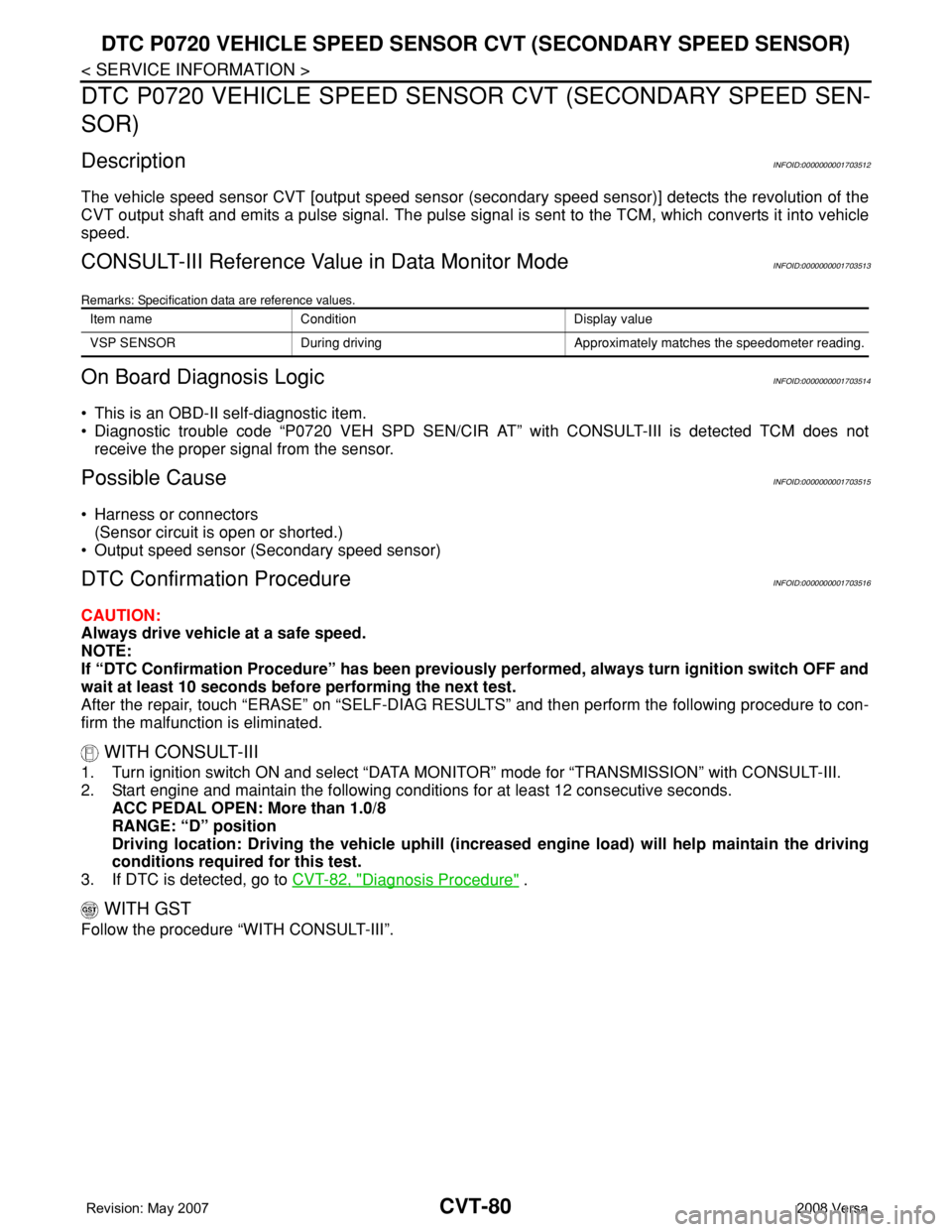
The vehicle speed sensor CVT [output speed sensor (secondary speed sensor)] detects the revolution of the
CVT output shaft and emits a pulse signal. The pulse signal is sent to the TCM, which converts it into vehicle
speed.
CONSULT-III Reference Value in Data Monitor ModeINFOID:0000000001703513
Remarks: Specification data are reference values.
On Board Diagnosis LogicINFOID:0000000001703514
• This is an OBD-II self-diagnostic item.
• Diagnostic trouble code “P0720 VEH SPD SEN/CIR AT” with CONSULT-III is detected TCM does not
receive the proper signal from the sensor.
Possible CauseINFOID:0000000001703515
• Harness or connectors
(Sensor circuit is open or shorted.)
• Output speed sensor (Secondary speed sensor)
DTC Confirmation ProcedureINFOID:0000000001703516
CAUTION:
Always drive vehicle at a safe speed.
NOTE:
If “DTC Confirmation Procedure” has been previously performed, always turn ignition switch OFF and
wait at least 10 seconds before performing the next test.
After the repair, touch “ERASE” on “SELF-DIAG RESULTS” and then perform the following procedure to con-
firm the malfunction is eliminated.
WITH CONSULT-III
1. Turn ignition switch ON and select “DATA MONITOR” mode for “TRANSMISSION” with CONSULT-III.
2. Start engine and maintain the following conditions for at least 12 consecutive seconds.
ACC PEDAL OPEN: More than 1.0/8
RANGE: “D” position
Driving location: Driving the vehicle uphill (increased engine load) will help maintain the driving
conditions required for this test.
3. If DTC is detected, go to CVT-82, "
Diagnosis Procedure" .
WITH GST
Follow the procedure “WITH CONSULT-III”.
Item name Condition Display value
VSP SENSOR During driving Approximately matches the speedometer reading.
Page 921 of 2771

CVT-82
< SERVICE INFORMATION >
DTC P0720 VEHICLE SPEED SENSOR CVT (SECONDARY SPEED SENSOR)
Diagnosis Procedure
INFOID:0000000001703518
1.CHECK INPUT SIGNAL
With CONSULT-III
1. Start engine.
2. Select “ECU INPUT SIGNALS” in “DATA MONITOR” mode for “TRANSMISSION” with CONSULT-III.
3. Start vehicle and read out the value of “VSP SENSOR”.
OK or NG
OK >> GO TO 8.
NG >> GO TO 2.
2. CHECK SECONDARY SPEED SENSOR
With CONSULT-III
1. Start engine.
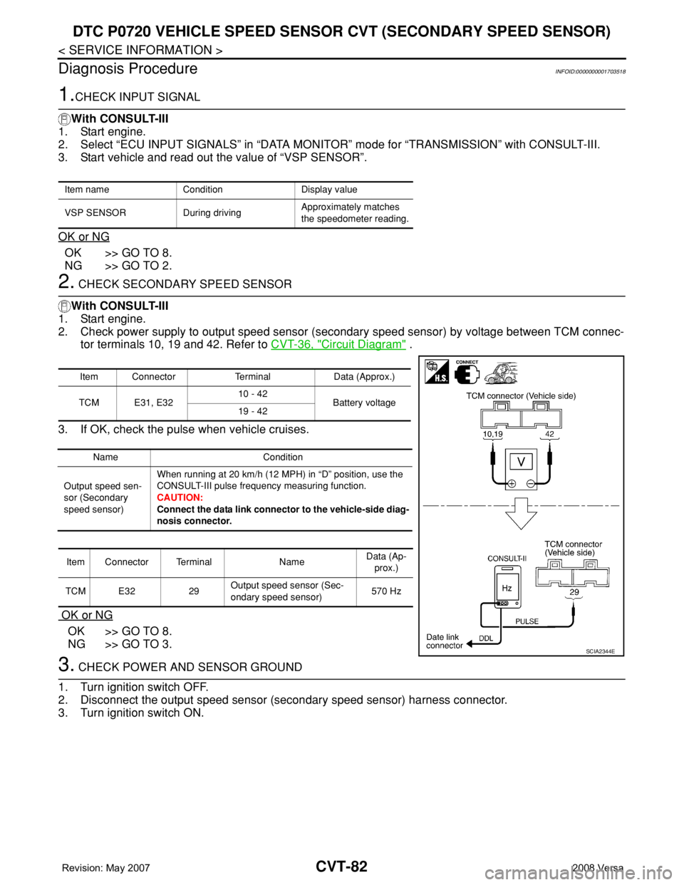
2. Check power supply to output speed sensor (secondary speed sensor) by voltage between TCM connec-
tor terminals 10, 19 and 42. Refer to CVT-36, "
Circuit Diagram" .
3. If OK, check the pulse when vehicle cruises.
OK or NG
OK >> GO TO 8.
NG >> GO TO 3.
3. CHECK POWER AND SENSOR GROUND
1. Turn ignition switch OFF.
2. Disconnect the output speed sensor (secondary speed sensor) harness connector.
3. Turn ignition switch ON.
Item name Condition Display value
VSP SENSOR During drivingApproximately matches
the speedometer reading.
Item Connector Terminal Data (Approx.)
TCM E31, E3210 - 42
Battery voltage
19 - 42
Name Condition
Output speed sen-
sor (Secondary
speed sensor)When running at 20 km/h (12 MPH) in “D” position, use the
CONSULT-III pulse frequency measuring function.
CAUTION:
Connect the data link connector to the vehicle-side diag-
nosis connector.
Item Connector Terminal NameData (Ap-
prox.)
TCM E32 29Output speed sensor (Sec-
ondary speed sensor)570 Hz
SCIA2344E