2008 NISSAN TIIDA oil filter
[x] Cancel search: oil filterPage 201 of 2771
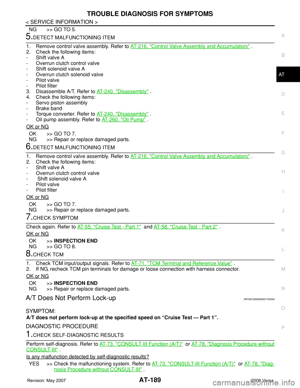
TROUBLE DIAGNOSIS FOR SYMPTOMS
AT-189
< SERVICE INFORMATION >
D
E
F
G
H
I
J
K
L
MA
B
AT
N
O
P
NG >> GO TO 5.
5.DETECT MALFUNCTIONING ITEM
1. Remove control valve assembly. Refer to AT-216, "
Control Valve Assembly and Accumulators" .
2. Check the following items:
- Shift valve A
- Overrun clutch control valve
- Shift solenoid valve A
- Overrun clutch solenoid valve
- Pilot valve
- Pilot filter
3. Disassemble A/T. Refer to AT-240, "
Disassembly" .
4. Check the following items:
- Servo piston assembly
- Brake band
- Torque converter. Refer to AT-240, "
Disassembly" .
- Oil pump assembly. Refer to AT-260, "
Oil Pump" .
OK or NG
OK >> GO TO 7.
NG >> Repair or replace damaged parts.
6.DETECT MALFUNCTIONING ITEM
1. Remove control valve assembly. Refer to AT-216, "
Control Valve Assembly and Accumulators" .
2. Check the following items:
- Shift valve A
- Overrun clutch control valve
- Shift solenoid valve A
- Pilot valve
- Pilot filter
OK or NG
OK >> GO TO 7.
NG >> Repair or replace damaged parts.
7.CHECK SYMPTOM
Check again. Refer to AT-55, "
Cruise Test - Part 1" and AT-58, "Cruise Test - Part 2" .
OK or NG
OK >>INSPECTION END
NG >> GO TO 8.
8.CHECK TCM
1. Check TCM input/output signals. Refer to AT-71, "
TCM Terminal and Reference Value" .
2. If NG, recheck TCM pin terminals for damage or loose connection with harness connector.
OK or NG
OK >>INSPECTION END
NG >> Repair or replace damaged parts.
A/T Does Not Perform Lock-upINFOID:0000000001703346
SYMPTOM:
A/T does not perform lock-up at the specified speed on “Cruise Test — Part 1”.
DIAGNOSTIC PROCEDURE
1.CHECK SELF-DIAGNOSTIC RESULTS
Perform self-diagnosis. Refer to AT-73, "
CONSULT-III Function (A/T)" or AT-78, "Diagnosis Procedure without
CONSULT-III" .
Is any malfunction detected by self-diagnostic results?
YES >> Check the malfunctioning system. Refer to AT-73, "CONSULT-III Function (A/T)" or AT-78, "Diag-
nosis Procedure without CONSULT-III" .
Page 202 of 2771
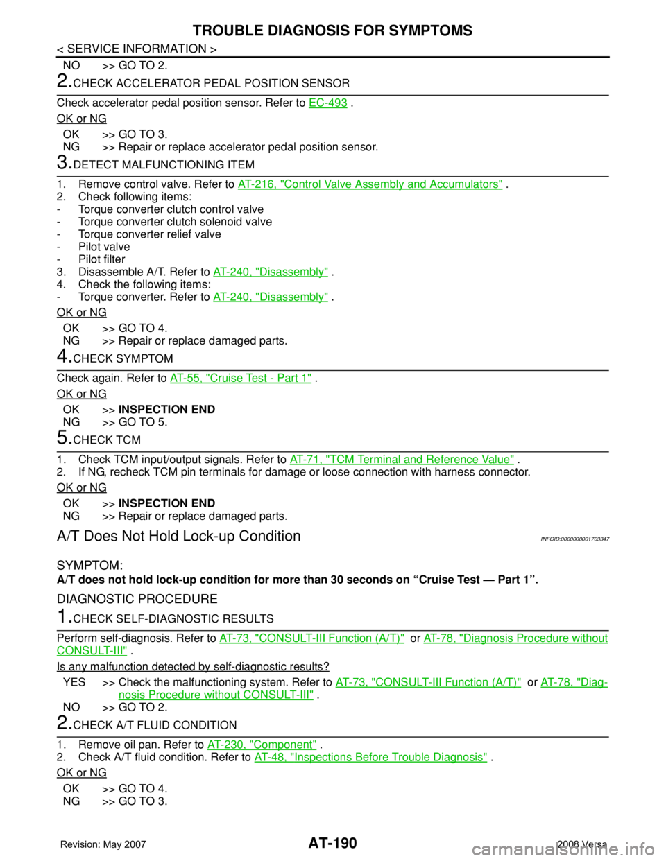
AT-190
< SERVICE INFORMATION >
TROUBLE DIAGNOSIS FOR SYMPTOMS
NO >> GO TO 2.
2.CHECK ACCELERATOR PEDAL POSITION SENSOR
Check accelerator pedal position sensor. Refer to EC-493
.
OK or NG
OK >> GO TO 3.
NG >> Repair or replace accelerator pedal position sensor.
3.DETECT MALFUNCTIONING ITEM
1. Remove control valve. Refer to AT-216, "
Control Valve Assembly and Accumulators" .
2. Check following items:
- Torque converter clutch control valve
- Torque converter clutch solenoid valve
- Torque converter relief valve
- Pilot valve
- Pilot filter
3. Disassemble A/T. Refer to AT-240, "
Disassembly" .
4. Check the following items:
- Torque converter. Refer to AT-240, "
Disassembly" .
OK or NG
OK >> GO TO 4.
NG >> Repair or replace damaged parts.
4.CHECK SYMPTOM
Check again. Refer to AT-55, "
Cruise Test - Part 1" .
OK or NG
OK >>INSPECTION END
NG >> GO TO 5.
5.CHECK TCM
1. Check TCM input/output signals. Refer to AT-71, "
TCM Terminal and Reference Value" .
2. If NG, recheck TCM pin terminals for damage or loose connection with harness connector.
OK or NG
OK >>INSPECTION END
NG >> Repair or replace damaged parts.
A/T Does Not Hold Lock-up ConditionINFOID:0000000001703347
SYMPTOM:
A/T does not hold lock-up condition for more than 30 seconds on “Cruise Test — Part 1”.
DIAGNOSTIC PROCEDURE
1.CHECK SELF-DIAGNOSTIC RESULTS
Perform self-diagnosis. Refer to AT-73, "
CONSULT-III Function (A/T)" or AT-78, "Diagnosis Procedure without
CONSULT-III" .
Is any malfunction detected by self-diagnostic results?
YES >> Check the malfunctioning system. Refer to AT-73, "CONSULT-III Function (A/T)" or AT-78, "Diag-
nosis Procedure without CONSULT-III" .
NO >> GO TO 2.
2.CHECK A/T FLUID CONDITION
1. Remove oil pan. Refer to AT-230, "
Component" .
2. Check A/T fluid condition. Refer to AT-48, "
Inspections Before Trouble Diagnosis" .
OK or NG
OK >> GO TO 4.
NG >> GO TO 3.
Page 203 of 2771
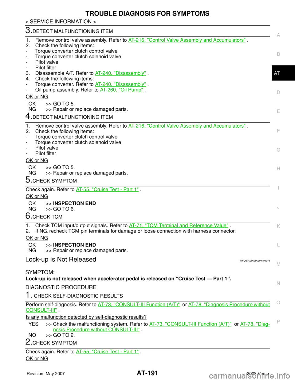
TROUBLE DIAGNOSIS FOR SYMPTOMS
AT-191
< SERVICE INFORMATION >
D
E
F
G
H
I
J
K
L
MA
B
AT
N
O
P
3.DETECT MALFUNCTIONING ITEM
1. Remove control valve assembly. Refer to AT-216, "
Control Valve Assembly and Accumulators" .
2. Check the following items:
- Torque converter clutch control valve
- Torque converter clutch solenoid valve
- Pilot valve
- Pilot filter
3. Disassemble A/T. Refer to AT-240, "
Disassembly" .
4. Check the following items:
- Torque converter. Refer to AT-240, "
Disassembly" .
- Oil pump assembly. Refer to AT-260, "
Oil Pump" .
OK or NG
OK >> GO TO 5.
NG >> Repair or replace damaged parts.
4.DETECT MALFUNCTIONING ITEM
1. Remove control valve assembly. Refer to AT-216, "
Control Valve Assembly and Accumulators" .
2. Check the following items:
- Torque converter clutch control valve
- Torque converter clutch solenoid valve
- Pilot valve
- Pilot filter
OK or NG
OK >> GO TO 5.
NG >> Repair or replace damaged parts.
5.CHECK SYMPTOM
Check again. Refer to AT-55, "
Cruise Test - Part 1" .
OK or NG
OK >>INSPECTION END
NG >> GO TO 6.
6.CHECK TCM
1. Check TCM input/output signals. Refer to AT-71, "
TCM Terminal and Reference Value" .
2. If NG, recheck TCM pin terminals for damage or loose connection with harness connector.
OK or NG
OK >>INSPECTION END
NG >> Repair or replace damaged parts.
Lock-up Is Not ReleasedINFOID:0000000001703348
SYMPTOM:
Lock-up is not released when accelerator pedal is released on “Cruise Test — Part 1”.
DIAGNOSTIC PROCEDURE
1. CHECK SELF-DIAGNOSTIC RESULTS
Perform self-diagnosis. Refer to AT-73, "
CONSULT-III Function (A/T)" or AT-78, "Diagnosis Procedure without
CONSULT-III" .
Is any malfunction detected by self-diagnostic results?
YES >> Check the malfunctioning system. Refer to AT-73, "CONSULT-III Function (A/T)" or AT-78, "Diag-
nosis Procedure without CONSULT-III" .
NO >> GO TO 2.
2.CHECK SYMPTOM
Check again. Refer to AT-55, "
Cruise Test - Part 1" .
OK or NG
Page 276 of 2771
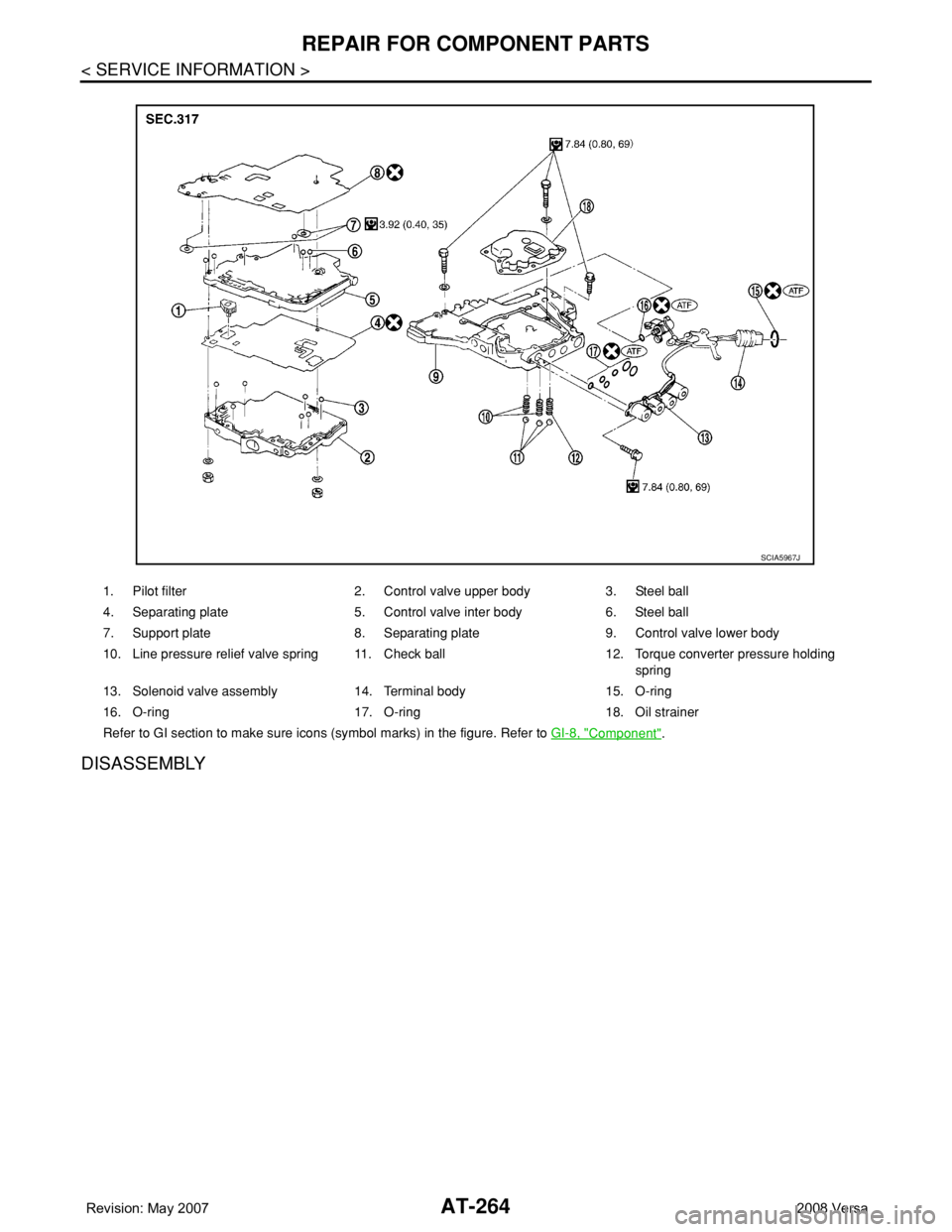
AT-264
< SERVICE INFORMATION >
REPAIR FOR COMPONENT PARTS
DISASSEMBLY
1. Pilot filter 2. Control valve upper body 3. Steel ball
4. Separating plate 5. Control valve inter body 6. Steel ball
7. Support plate 8. Separating plate 9. Control valve lower body
10. Line pressure relief valve spring 11. Check ball 12. Torque converter pressure holding
spring
13. Solenoid valve assembly 14. Terminal body 15. O-ring
16. O-ring 17. O-ring 18. Oil strainer
Refer to GI section to make sure icons (symbol marks) in the figure. Refer to GI-8, "
Component".
SCIA5967J
Page 745 of 2771
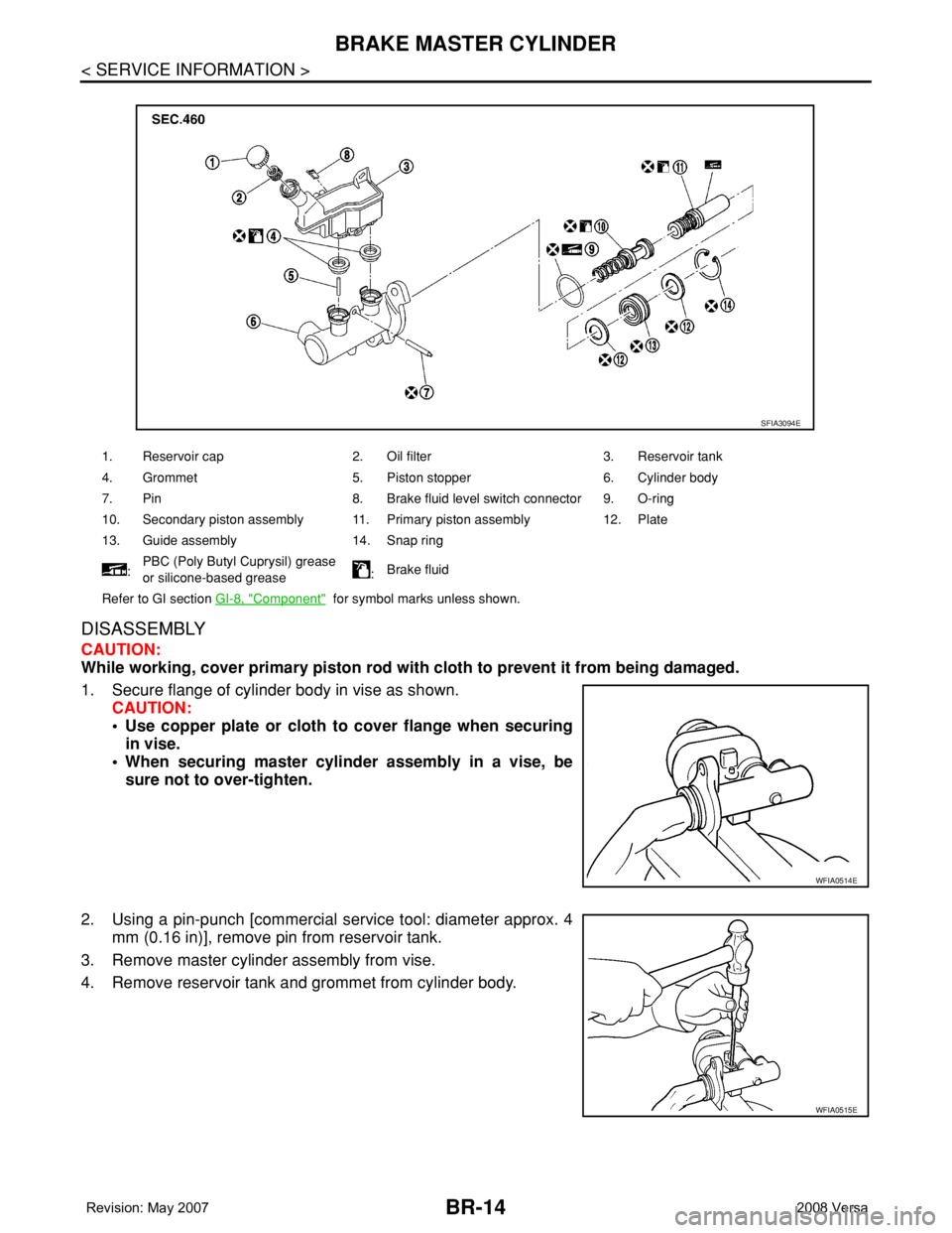
BR-14
< SERVICE INFORMATION >
BRAKE MASTER CYLINDER
DISASSEMBLY
CAUTION:
While working, cover primary piston rod with cloth to prevent it from being damaged.
1. Secure flange of cylinder body in vise as shown.
CAUTION:
• Use copper plate or cloth to cover flange when securing
in vise.
• When securing master cylinder assembly in a vise, be
sure not to over-tighten.
2. Using a pin-punch [commercial service tool: diameter approx. 4
mm (0.16 in)], remove pin from reservoir tank.
3. Remove master cylinder assembly from vise.
4. Remove reservoir tank and grommet from cylinder body.
1. Reservoir cap 2. Oil filter 3. Reservoir tank
4. Grommet 5. Piston stopper 6. Cylinder body
7. Pin 8. Brake fluid level switch connector 9. O-ring
10. Secondary piston assembly 11. Primary piston assembly 12. Plate
13. Guide assembly 14. Snap ring
:PBC (Poly Butyl Cuprysil) grease
or silicone-based grease:Brake fluid
Refer to GI section GI-8, "
Component" for symbol marks unless shown.
SFIA3094E
WFIA0514E
WFIA0515E
Page 856 of 2771
CVT FLUID
CVT-17
< SERVICE INFORMATION >
D
E
F
G
H
I
J
K
L
MA
B
CVT
N
O
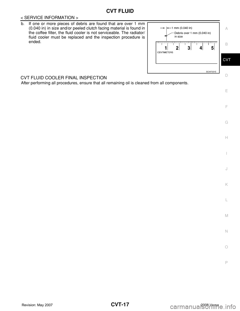
P
b. If one or more pieces of debris are found that are over 1 mm
(0.040 in) in size and/or peeled clutch facing material is found in
the coffee filter, the fluid cooler is not serviceable. The radiator/
fluid cooler must be replaced and the inspection procedure is
ended.
CVT FLUID COOLER FINAL INSPECTION
After performing all procedures, ensure that all remaining oil is cleaned from all components.
SCIA7031E
Page 879 of 2771

CVT-40
< SERVICE INFORMATION >
TROUBLE DIAGNOSIS
Road Test
INFOID:0000000001703457
DESCRIPTION
• The purpose of the test is to determine overall performance of CVT
and analyze causes of problems.
• The road test consists of the following three parts:
1. “Check Before Engine Is Started”CVT-41
.
2. “Check at Idle”CVT-41
.
3. “Cruise Test”CVT-43
.
Judgement Possible cause
Idle speedLow for all positions
(“P”, “R”, “N”, “D”, “L”)Possible causes include malfunctions in the pressure supply system and low oil pump output.
For example
•Oil pump wear
• Pressure regulator valve or plug sticking or spring fatigue
•Oil strainer ⇒ oil pump ⇒ pressure regulator valve passage oil leak
• Engine idle speed too low
Only low for a specific
positionPossible causes include an oil pressure leak in a passage or device related to the position after
the pressure is distributed by the manual valve.
HighPossible causes include a sensor malfunction or malfunction in the line pressure adjustment
function.
For example
• Accelerator pedal position signal malfunction
• CVT fluid temperature sensor malfunction
• Pressure control solenoid A (line pressure solenoid) malfunction (sticking in OFF state, filter
clog, cut line)
• Pressure regulator valve or plug sticking
Sta ll sp ee dLine pressure does
not rise higher than
the line pressure for
idle.Possible causes include a sensor malfunction or malfunction in the pressure adjustment func-
tion.
For example
• Accelerator pedal position signal malfunction
•TCM malfunction
• Pressure control solenoid A (line pressure solenoid) malfunction (shorting, sticking in ON
state)
• Pressure regulator valve or plug sticking
The pressure rises,
but does not enter the
standard position.Possible causes include malfunctions in the pressure supply system and malfunction in the pres-
sure adjustment function.
For example
• Accelerator pedal position signal malfunction
• Pressure control solenoid A (line pressure solenoid) malfunction (sticking, filter clog)
• Pressure regulator valve or plug sticking
Only low for a specific
positionPossible causes include an oil pressure leak in a passage or device related to the position after
the pressure is distributed by the manual valve.
SAT786A
Page 1154 of 2771
EC-80
< SERVICE INFORMATION >
BASIC SERVICE PROCEDURE
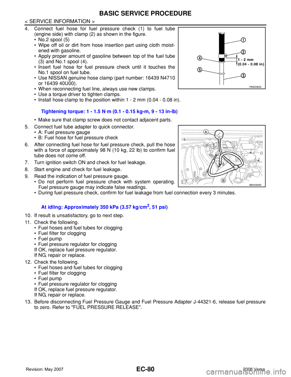
4. Connect fuel hose for fuel pressure check (1) to fuel tube
(engine side) with clamp (2) as shown in the figure.
• No.2 spool (5)
• Wipe off oil or dirt from hose insertion part using cloth moist-
ened with gasoline.
• Apply proper amount of gasoline between top of the fuel tube
(3) and No.1 spool (4).
• Insert fuel hose for fuel pressure check until it touches the
No.1 spool on fuel tube.
• Use NISSAN genuine hose clamp (part number: 16439 N4710
or 16439 40U00).
• When reconnecting fuel line, always use new clamps.
• Use a torque driver to tighten clamps.
• Install hose clamp to the position within 1 - 2 mm (0.04 - 0.08 in).
• Make sure that clamp screw does not contact adjacent parts.
5. Connect fuel tube adapter to quick connector.
• A: Fuel pressure gauge
• B: Fuel hose for fuel pressure check
6. After connecting fuel hose for fuel pressure check, pull the hose
with a force of approximately 98 N (10 kg, 22 lb) to confirm fuel
tube does not come off.
7. Turn ignition switch ON and check for fuel leakage.
8. Start engine and check for fuel leakage.
9. Read the indication of fuel pressure gauge.
• Do not perform fuel pressure check with system operating.
Fuel pressure gauge may indicate false readings.
• During fuel pressure check, confirm for fuel leakage from fuel connection every 3 minutes.
10. If result is unsatisfactory, go to next step.
11. Check the following.
• Fuel hoses and fuel tubes for clogging
• Fuel filter for clogging
• Fuel pump
• Fuel pressure regulator for clogging
If OK, replace fuel pressure regulator.
If NG, repair or replace.
12. Check the following.
• Fuel hoses and fuel tubes for clogging
• Fuel filter for clogging
• Fuel pump
• Fuel pressure regulator for clogging
If OK, replace fuel pressure regulator.
If NG, repair or replace.
13. Before disconnecting Fuel Pressure Gauge and Fuel Pressure Adapter J-44321-6, release fuel pressure
to zero. Refer to "FUEL PRESSURE RELEASE".Tightening torque: 1 - 1.5 N·m (0.1 - 0.15 kg-m, 9 - 13 in-lb)
At idling: Approximately 350 kPa (3.57 kg/cm
2, 51 psi)
PBIB2983E
BBIA0695E