2008 NISSAN TIIDA oil filter
[x] Cancel search: oil filterPage 1732 of 2771
CAMSHAFT
EM-55
< SERVICE INFORMATION >
C
D
E
F
G
H
I
J
K
L
MA
EM
N
P O
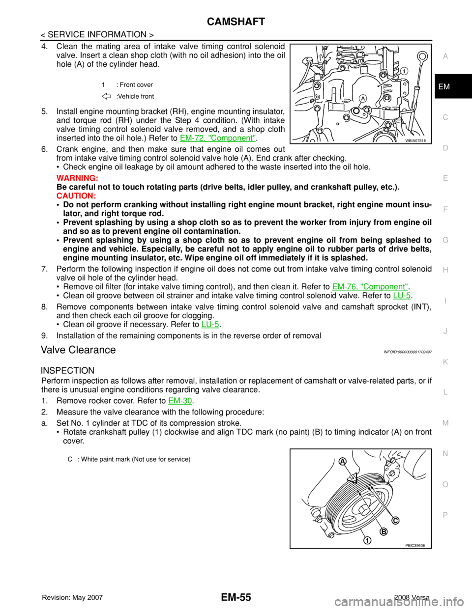
4. Clean the mating area of intake valve timing control solenoid
valve. Insert a clean shop cloth (with no oil adhesion) into the oil
hole (A) of the cylinder head.
5. Install engine mounting bracket (RH), engine mounting insulator,
and torque rod (RH) under the Step 4 condition. (With intake
valve timing control solenoid valve removed, and a shop cloth
inserted into the oil hole.) Refer to EM-72, "
Component".
6. Crank engine, and then make sure that engine oil comes out
from intake valve timing control solenoid valve hole (A). End crank after checking.
• Check engine oil leakage by oil amount adhered to the waste inserted into the oil hole.
WARNING:
Be careful not to touch rotating parts (drive belts, idler pulley, and crankshaft pulley, etc.).
CAUTION:
• Do not perform cranking without installing right engine mount bracket, right engine mount insu-
lator, and right torque rod.
• Prevent splashing by using a shop cloth so as to prevent the worker from injury from engine oil
and so as to prevent engine oil contamination.
• Prevent splashing by using a shop cloth so as to prevent engine oil from being splashed to
engine and vehicle. Especially, be careful not to apply engine oil to rubber parts of drive belts,
engine mounting insulator, etc. Wipe engine oil off immediately if it is splashed.
7. Perform the following inspection if engine oil does not come out from intake valve timing control solenoid
valve oil hole of the cylinder head.
• Remove oil filter (for intake valve timing control), and then clean it. Refer to EM-76, "
Component".
• Clean oil groove between oil strainer and intake valve timing control solenoid valve. Refer to LU-5
.
8. Remove components between intake valve timing control solenoid valve and camshaft sprocket (INT),
and then check each oil groove for clogging.
• Clean oil groove if necessary. Refer to LU-5
.
9. Installation of the remaining components is in the reverse order of removal
Valve ClearanceINFOID:0000000001702497
INSPECTION
Perform inspection as follows after removal, installation or replacement of camshaft or valve-related parts, or if
there is unusual engine conditions regarding valve clearance.
1. Remove rocker cover. Refer to EM-30
.
2. Measure the valve clearance with the following procedure:
a. Set No. 1 cylinder at TDC of its compression stroke.
• Rotate crankshaft pulley (1) clockwise and align TDC mark (no paint) (B) to timing indicator (A) on front
cover.
1 : Front cover
:Vehicle front
WBIA0781E
C : White paint mark (Not use for service)
PBIC3960E
Page 1753 of 2771
EM-76
< SERVICE INFORMATION >
CYLINDER BLOCK
CYLINDER BLOCK
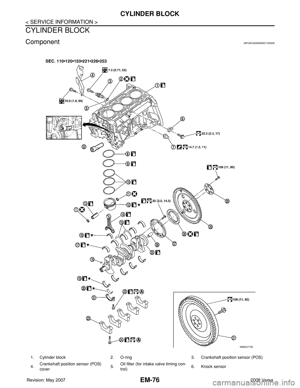
ComponentINFOID:0000000001702509
1. Cylinder block 2. O-ring 3. Crankshaft position sensor (POS)
4.Crankshaft position sensor (POS)
cover5.Oil filter (for intake valve timing con-
trol)6. Knock sensor
WBIA0773E
Page 1755 of 2771
EM-78
< SERVICE INFORMATION >
CYLINDER BLOCK
CAUTION:
• Avoid impacts such as a dropping.
• Never disassemble.
• Keep it away from metal particles.
• Never place sensor in a location where it is exposed to magnetism.
8. Remove oil filter (for intake valve timing control).
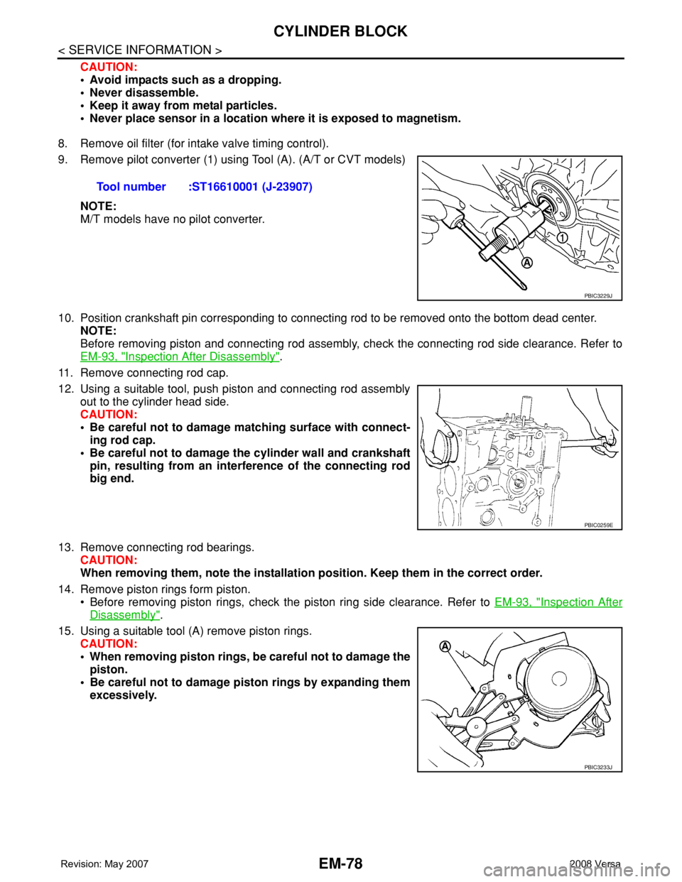
9. Remove pilot converter (1) using Tool (A). (A/T or CVT models)
NOTE:
M/T models have no pilot converter.
10. Position crankshaft pin corresponding to connecting rod to be removed onto the bottom dead center.
NOTE:
Before removing piston and connecting rod assembly, check the connecting rod side clearance. Refer to
EM-93, "
Inspection After Disassembly".
11. Remove connecting rod cap.
12. Using a suitable tool, push piston and connecting rod assembly
out to the cylinder head side.
CAUTION:
• Be careful not to damage matching surface with connect-
ing rod cap.
• Be careful not to damage the cylinder wall and crankshaft
pin, resulting from an interference of the connecting rod
big end.
13. Remove connecting rod bearings.
CAUTION:
When removing them, note the installation position. Keep them in the correct order.
14. Remove piston rings form piston.
• Before removing piston rings, check the piston ring side clearance. Refer to EM-93, "
Inspection After
Disassembly".
15. Using a suitable tool (A) remove piston rings.
CAUTION:
• When removing piston rings, be careful not to damage the
piston.
• Be careful not to damage piston rings by expanding them
excessively.Tool number :ST16610001 (J-23907)
PBIC3229J
PBIC0259E
PBIC3233J
Page 1762 of 2771
CYLINDER BLOCK
EM-85
< SERVICE INFORMATION >
C
D
E
F
G
H
I
J
K
L
MA
EM
N
P O
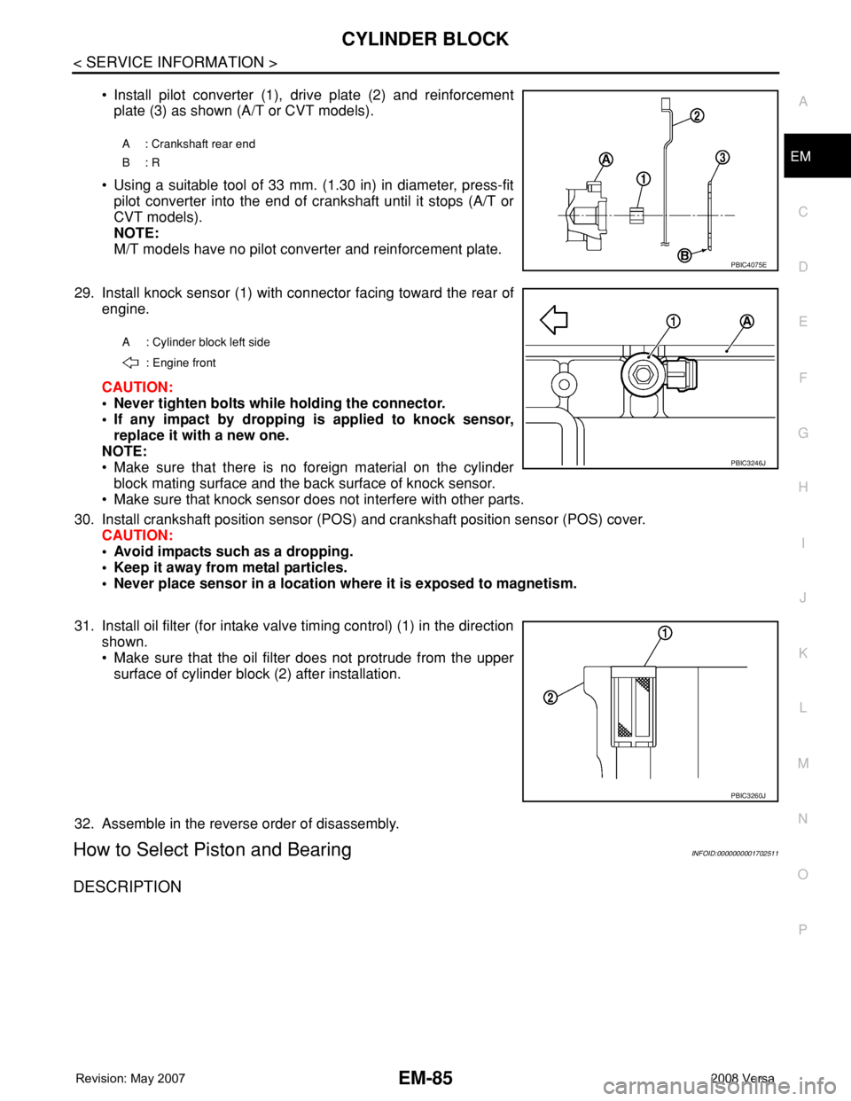
• Install pilot converter (1), drive plate (2) and reinforcement
plate (3) as shown (A/T or CVT models).
• Using a suitable tool of 33 mm. (1.30 in) in diameter, press-fit
pilot converter into the end of crankshaft until it stops (A/T or
CVT models).
NOTE:
M/T models have no pilot converter and reinforcement plate.
29. Install knock sensor (1) with connector facing toward the rear of
engine.
CAUTION:
• Never tighten bolts while holding the connector.
• If any impact by dropping is applied to knock sensor,
replace it with a new one.
NOTE:
• Make sure that there is no foreign material on the cylinder
block mating surface and the back surface of knock sensor.
• Make sure that knock sensor does not interfere with other parts.
30. Install crankshaft position sensor (POS) and crankshaft position sensor (POS) cover.
CAUTION:
• Avoid impacts such as a dropping.
• Keep it away from metal particles.
• Never place sensor in a location where it is exposed to magnetism.
31. Install oil filter (for intake valve timing control) (1) in the direction
shown.
• Make sure that the oil filter does not protrude from the upper
surface of cylinder block (2) after installation.
32. Assemble in the reverse order of disassembly.
How to Select Piston and BearingINFOID:0000000001702511
DESCRIPTION
A : Crankshaft rear end
B: R
PBIC4075E
A : Cylinder block left side
: Engine front
PBIC3246J
PBIC3260J
Page 1779 of 2771
EM-102
< SERVICE INFORMATION >
CYLINDER BLOCK
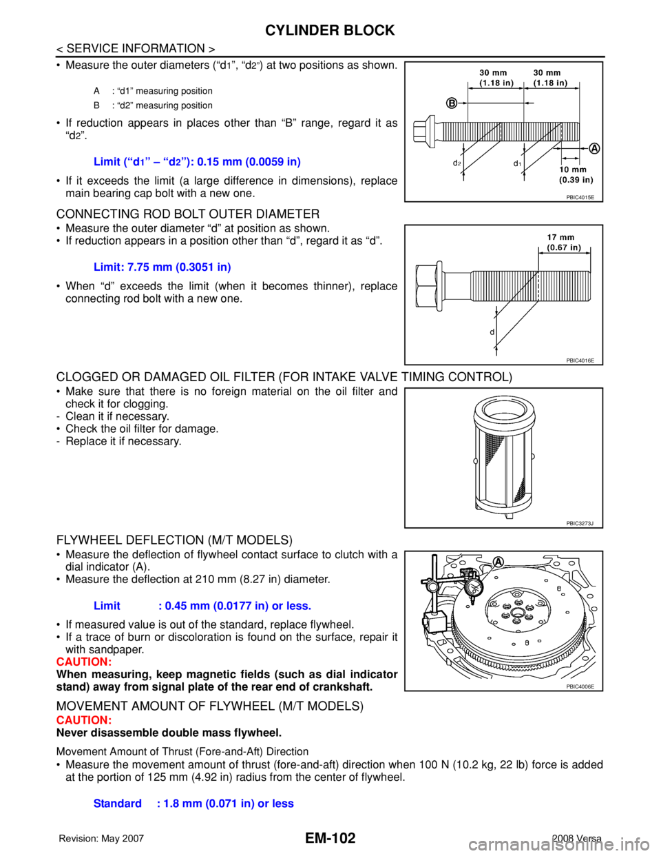
• Measure the outer diameters (“d1”, “d2”) at two positions as shown.
• If reduction appears in places other than “B” range, regard it as
“d
2”.
• If it exceeds the limit (a large difference in dimensions), replace
main bearing cap bolt with a new one.
CONNECTING ROD BOLT OUTER DIAMETER
• Measure the outer diameter “d” at position as shown.
• If reduction appears in a position other than “d”, regard it as “d”.
• When “d” exceeds the limit (when it becomes thinner), replace
connecting rod bolt with a new one.
CLOGGED OR DAMAGED OIL FILTER (FOR INTAKE VALVE TIMING CONTROL)
• Make sure that there is no foreign material on the oil filter and
check it for clogging.
- Clean it if necessary.
• Check the oil filter for damage.
- Replace it if necessary.
FLYWHEEL DEFLECTION (M/T MODELS)
• Measure the deflection of flywheel contact surface to clutch with a
dial indicator (A).
• Measure the deflection at 210 mm (8.27 in) diameter.
• If measured value is out of the standard, replace flywheel.
• If a trace of burn or discoloration is found on the surface, repair it
with sandpaper.
CAUTION:
When measuring, keep magnetic fields (such as dial indicator
stand) away from signal plate of the rear end of crankshaft.
MOVEMENT AMOUNT OF FLYWHEEL (M/T MODELS)
CAUTION:
Never disassemble double mass flywheel.
Movement Amount of Thrust (Fore-and-Aft) Direction
• Measure the movement amount of thrust (fore-and-aft) direction when 100 N (10.2 kg, 22 lb) force is added
at the portion of 125 mm (4.92 in) radius from the center of flywheel.
A : “d1” measuring position
B : “d2” measuring position
Limit (“d1” – “d2”): 0.15 mm (0.0059 in)
PBIC4015E
Limit: 7.75 mm (0.3051 in)
PBIC4016E
PBIC3273J
Limit : 0.45 mm (0.0177 in) or less.
PBIC4006E
Standard : 1.8 mm (0.071 in) or less
Page 2251 of 2771
LU-1
ENGINE
C
D
E
F
G
H
I
J
K
L
M
SECTION LU
A
LU
N
O
P
CONTENTS
ENGINE LUBRICATION SYSTEM
SERVICE INFORMATION ............................2
PRECAUTIONS ...................................................2
Precaution for Supplemental Restraint System
(SRS) "AIR BAG" and "SEAT BELT PRE-TEN-
SIONER" ...................................................................
2
Precaution for Liquid Gasket .....................................2
PREPARATION ...................................................3
Special Service Tool .................................................3
Commercial Service Tool ..........................................3
LUBRICATION SYSTEM ....................................5
Lubrication Circuit .....................................................5
ENGINE OIL .......................................................6
Inspection .................................................................6
Changing Engine Oil .................................................7
OIL FILTER ........................................................9
Removal and Installation ..........................................9
SERVICE DATA AND SPECIFICATIONS
(SDS) .................................................................
10
Standard and Limit ..................................................10
Page 2253 of 2771
PREPARATION
LU-3
< SERVICE INFORMATION >
C
D
E
F
G
H
I
J
K
L
MA
LU
N
P O
PREPARATION
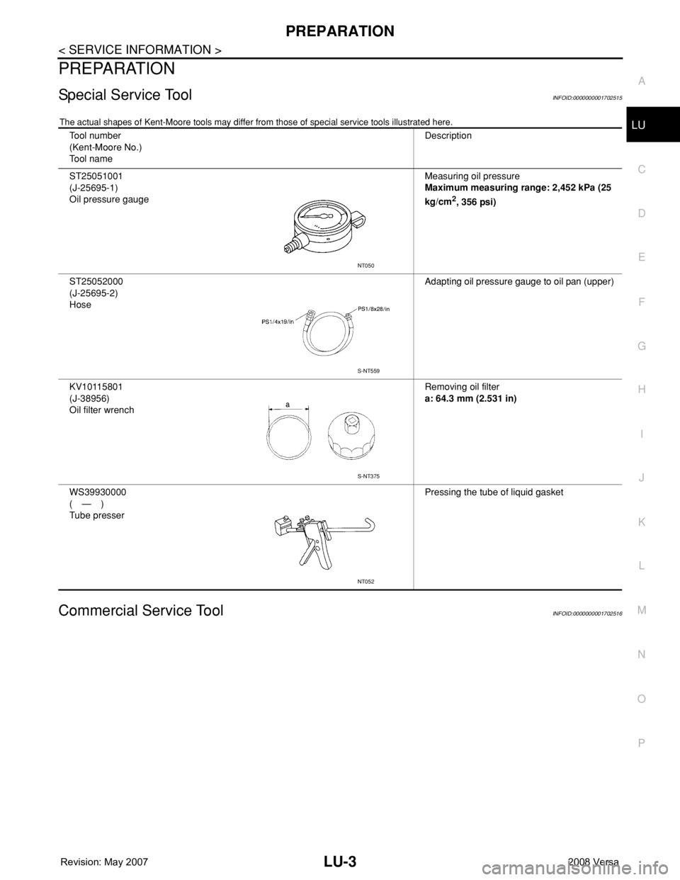
Special Service ToolINFOID:0000000001702515
The actual shapes of Kent-Moore tools may differ from those of special service tools illustrated here.
Commercial Service ToolINFOID:0000000001702516
Tool number
(Kent-Moore No.)
Tool nameDescription
ST25051001
(J-25695-1)
Oil pressure gaugeMeasuring oil pressure
Maximum measuring range: 2,452 kPa (25
kg/cm
2, 356 psi)
ST25052000
(J-25695-2)
HoseAdapting oil pressure gauge to oil pan (upper)
KV10115801
(J-38956)
Oil filter wrenchRemoving oil filter
a: 64.3 mm (2.531 in)
WS39930000
(—)
Tube presserPressing the tube of liquid gasket
NT050
S-NT559
S-NT375
NT052
Page 2256 of 2771
LU-6
< SERVICE INFORMATION >
ENGINE OIL
ENGINE OIL
InspectionINFOID:0000000001702518
ENGINE OIL LEVEL
NOTE:
Before starting engine, park vehicle on a level surface and check the engine oil level. If engine is already
started, stop it and allow 10 minutes before checking.
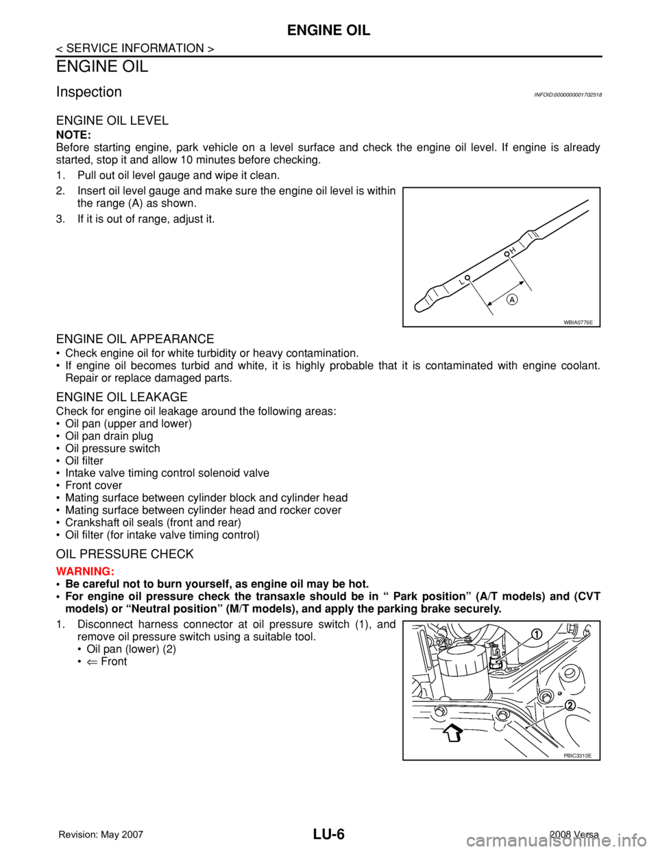
1. Pull out oil level gauge and wipe it clean.
2. Insert oil level gauge and make sure the engine oil level is within
the range (A) as shown.
3. If it is out of range, adjust it.
ENGINE OIL APPEARANCE
• Check engine oil for white turbidity or heavy contamination.
• If engine oil becomes turbid and white, it is highly probable that it is contaminated with engine coolant.
Repair or replace damaged parts.
ENGINE OIL LEAKAGE
Check for engine oil leakage around the following areas:
• Oil pan (upper and lower)
• Oil pan drain plug
• Oil pressure switch
• Oil filter
• Intake valve timing control solenoid valve
• Front cover
• Mating surface between cylinder block and cylinder head
• Mating surface between cylinder head and rocker cover
• Crankshaft oil seals (front and rear)
• Oil filter (for intake valve timing control)
OIL PRESSURE CHECK
WARNING:
• Be careful not to burn yourself, as engine oil may be hot.
• For engine oil pressure check the transaxle should be in “ Park position” (A/T models) and (CVT
models) or “Neutral position” (M/T models), and apply the parking brake securely.
1. Disconnect harness connector at oil pressure switch (1), and
remove oil pressure switch using a suitable tool.
• Oil pan (lower) (2)
•⇐ Front
WBIA0776E
PBIC3310E