2008 NISSAN TIIDA air vent
[x] Cancel search: air ventPage 239 of 2771
TRANSAXLE ASSEMBLY
AT-227
< SERVICE INFORMATION >
D
E
F
G
H
I
J
K
L
MA
B
AT
N
O
P
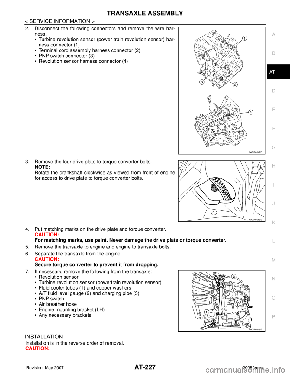
2. Disconnect the following connectors and remove the wire har-
ness.
• Turbine revolution sensor (power train revolution sensor) har-
ness connector (1)
• Terminal cord assembly harness connector (2)
• PNP switch connector (3)
• Revolution sensor harness connector (4)
3. Remove the four drive plate to torque converter bolts.
NOTE:
Rotate the crankshaft clockwise as viewed from front of engine
for access to drive plate to torque converter bolts.
4. Put matching marks on the drive plate and torque converter.
CAUTION:
For matching marks, use paint. Never damage the drive plate or torque converter.
5. Remove the transaxle to engine and engine to transaxle bolts.
6. Separate the transaxle from the engine.
CAUTION:
Secure torque converter to prevent it from dropping.
7. If necessary, remove the following from the transaxle:
• Revolution sensor
• Turbine revolution sensor (powertrain revolution sensor)
• Fluid cooler tubes (1) and copper washers
• A/T fluid level gauge (2) and charging pipe (3)
• PNP switch
• Air breather hose
• Engine mounting bracket (LH)
• Any necessary brackets
INSTALLATION
Installation is in the reverse order of removal.
CAUTION:
WCIA0647E
WCIA0616E
WCIA0648E
Page 286 of 2771
AT-274
< SERVICE INFORMATION >
REPAIR FOR COMPONENT PARTS
DISASSEMBLY
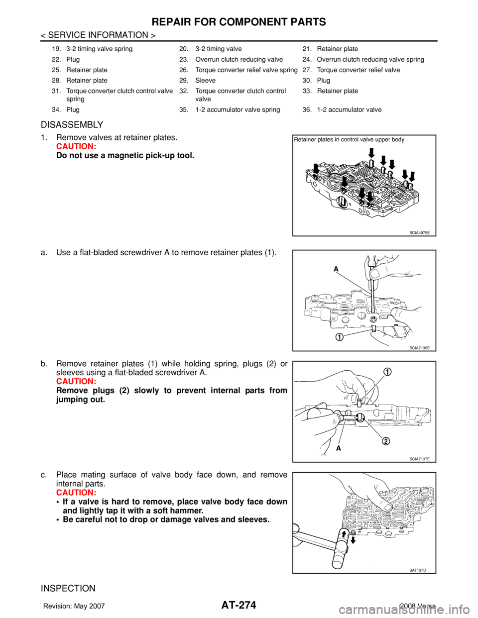
1. Remove valves at retainer plates.
CAUTION:
Do not use a magnetic pick-up tool.
a. Use a flat-bladed screwdriver A to remove retainer plates (1).
b. Remove retainer plates (1) while holding spring, plugs (2) or
sleeves using a flat-bladed screwdriver A.
CAUTION:
Remove plugs (2) slowly to prevent internal parts from
jumping out.
c. Place mating surface of valve body face down, and remove
internal parts.
CAUTION:
• If a valve is hard to remove, place valve body face down
and lightly tap it with a soft hammer.
• Be careful not to drop or damage valves and sleeves.
INSPECTION
19. 3-2 timing valve spring 20. 3-2 timing valve 21. Retainer plate
22. Plug 23. Overrun clutch reducing valve 24. Overrun clutch reducing valve spring
25. Retainer plate 26. Torque converter relief valve spring 27. Torque converter relief valve
28. Retainer plate 29. Sleeve 30. Plug
31. Torque converter clutch control valve
spring32. Torque converter clutch control
valve33. Retainer plate
34. Plug 35. 1-2 accumulator valve spring 36. 1-2 accumulator valve
SCIA4979E
SCIA7136E
SCIA7137E
SAT137D
Page 300 of 2771
AT-288
< SERVICE INFORMATION >
REPAIR FOR COMPONENT PARTS
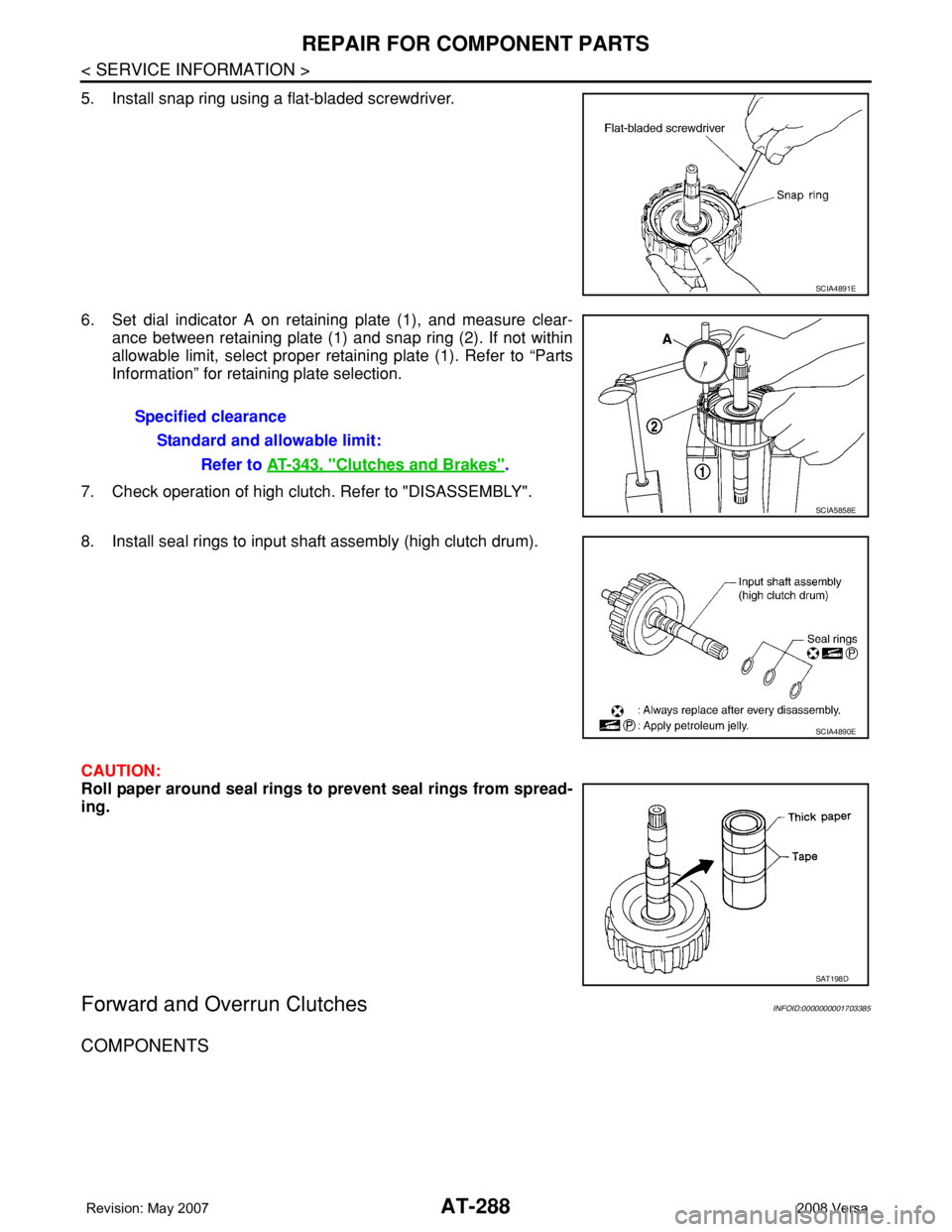
5. Install snap ring using a flat-bladed screwdriver.
6. Set dial indicator A on retaining plate (1), and measure clear-
ance between retaining plate (1) and snap ring (2). If not within
allowable limit, select proper retaining plate (1). Refer to “Parts
Information” for retaining plate selection.
7. Check operation of high clutch. Refer to "DISASSEMBLY".
8. Install seal rings to input shaft assembly (high clutch drum).
CAUTION:
Roll paper around seal rings to prevent seal rings from spread-
ing.
Forward and Overrun ClutchesINFOID:0000000001703385
COMPONENTS
SCIA4891E
Specified clearance
Standard and allowable limit:
Refer to AT-343, "
Clutches and Brakes".
SCIA5858E
SCIA4890E
SAT198D
Page 319 of 2771
![NISSAN TIIDA 2008 Service Repair Manual REPAIR FOR COMPONENT PARTS
AT-307
< SERVICE INFORMATION >
D
E
F
G
H
I
J
K
L
MA
B
AT
N
O
P
6. Set drift [commercial service tool] on radial needle bearing, and
press radial needle bearing into bearing NISSAN TIIDA 2008 Service Repair Manual REPAIR FOR COMPONENT PARTS
AT-307
< SERVICE INFORMATION >
D
E
F
G
H
I
J
K
L
MA
B
AT
N
O
P
6. Set drift [commercial service tool] on radial needle bearing, and
press radial needle bearing into bearing](/manual-img/5/57399/w960_57399-318.png)
REPAIR FOR COMPONENT PARTS
AT-307
< SERVICE INFORMATION >
D
E
F
G
H
I
J
K
L
MA
B
AT
N
O
P
6. Set drift [commercial service tool] on radial needle bearing, and
press radial needle bearing into bearing retainer.
7. Install snap ring to bearing retainer.
8. After packing ring grooves with petroleum jelly, carefully install
new seal rings (1) on output shaft (2) and bearing retainer (3).
CAUTION:
Roll paper around seal rings to prevent seal rings from
spreading.
Band Servo Piston AssemblyINFOID:0000000001703389
COMPONENTS
SAT658D
SAT659D
SCIA7996E
SCIA8011E
Page 328 of 2771
AT-316
< SERVICE INFORMATION >
REPAIR FOR COMPONENT PARTS
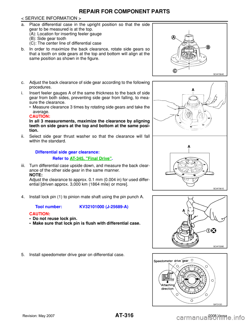
a. Place differential case in the upright position so that the side
gear to be measured is at the top.
(A): Location for inserting feeler gauge
(B): Side gear tooth
(C): The center line of differential case
b. In order to maximize the back clearance, rotate side gears so
that a tooth on side gears at the top and bottom will align at the
same position as shown in the figure.
c. Adjust the back clearance of side gear according to the following
procedures.
i. Insert feeler gauges A of the same thickness to the back of side
gear from both sides, preventing side gear from falling, to mea-
sure the clearance.
• Measure clearance 3 times by rotating side gears and take the
average.
CAUTION:
In all 3 measurements, maximize the clearance by aligning
teeth on side gears at the top and bottom at the same posi-
tion.
ii. Select side gear thrust washer so that the clearance will fall
within the standard.
iii. Turn differential case upside down, and measure the back clear-
ance of the other side gear in the same manner.
NOTE:
Adjust the clearance to approx. 0.1 mm (0.004 in) for used differ-
ential [driven approx. 3,000 km (1864 mile) or more].
4. Install lock pin (1) to pinion mate shaft using the pin punch A.
CAUTION:
• Do not reuse lock pin.
• Make sure that lock pin is flush with differential case.
5. Install speedometer drive gear on differential case.
SCIA7064E
Differential side gear clearance:
Refer to AT-345, "
Final Drive".
SCIA7061E
Tool number: KV32101000 (J-25689-A)
SCIA7228E
SAT313D
Page 361 of 2771
AV-2
< SERVICE INFORMATION >
PRECAUTIONS
SERVICE INFORMATION
PRECAUTIONS
Precaution for Supplemental Restraint System (SRS) "AIR BAG" and "SEAT BELT
PRE-TENSIONER"
INFOID:0000000001704647
The Supplemental Restraint System such as “AIR BAG” and “SEAT BELT PRE-TENSIONER”, used along
with a front seat belt, helps to reduce the risk or severity of injury to the driver and front passenger for certain
types of collision. This system includes seat belt switch inputs and dual stage front air bag modules. The SRS
system uses the seat belt switches to determine the front air bag deployment, and may only deploy one front
air bag, depending on the severity of a collision and whether the front occupants are belted or unbelted.
Information necessary to service the system safely is included in the SR and SB section of this Service Man-
ual.
WARNING:
• To avoid rendering the SRS inoperative, which could increase the risk of personal injury or death in
the event of a collision which would result in air bag inflation, all maintenance must be performed by
an authorized NISSAN/INFINITI dealer.
• Improper maintenance, including incorrect removal and installation of the SRS, can lead to personal
injury caused by unintentional activation of the system. For removal of Spiral Cable and Air Bag
Module, see the SR section.
• Do not use electrical test equipment on any circuit related to the SRS unless instructed to in this
Service Manual. SRS wiring harnesses can be identified by yellow and/or orange harnesses or har-
ness connectors.
Page 418 of 2771
BCS-2
< SERVICE INFORMATION >
PRECAUTIONS
SERVICE INFORMATION
PRECAUTIONS
Precaution for Supplemental Restraint System (SRS) "AIR BAG" and "SEAT BELT
PRE-TENSIONER"
INFOID:0000000001704583
The Supplemental Restraint System such as “AIR BAG” and “SEAT BELT PRE-TENSIONER”, used along
with a front seat belt, helps to reduce the risk or severity of injury to the driver and front passenger for certain
types of collision. This system includes seat belt switch inputs and dual stage front air bag modules. The SRS
system uses the seat belt switches to determine the front air bag deployment, and may only deploy one front
air bag, depending on the severity of a collision and whether the front occupants are belted or unbelted.
Information necessary to service the system safely is included in the SR and SB section of this Service Man-
ual.
WARNING:
• To avoid rendering the SRS inoperative, which could increase the risk of personal injury or death in
the event of a collision which would result in air bag inflation, all maintenance must be performed by
an authorized NISSAN/INFINITI dealer.
• Improper maintenance, including incorrect removal and installation of the SRS, can lead to personal
injury caused by unintentional activation of the system. For removal of Spiral Cable and Air Bag
Module, see the SR section.
• Do not use electrical test equipment on any circuit related to the SRS unless instructed to in this
Service Manual. SRS wiring harnesses can be identified by yellow and/or orange harnesses or har-
ness connectors.
Page 438 of 2771
BL-4
< SERVICE INFORMATION >
PRECAUTIONS
SERVICE INFORMATION
PRECAUTIONS
Precaution for Supplemental Restraint System (SRS) "AIR BAG" and "SEAT BELT
PRE-TENSIONER"
INFOID:0000000001703938
The Supplemental Restraint System such as “AIR BAG” and “SEAT BELT PRE-TENSIONER”, used along
with a front seat belt, helps to reduce the risk or severity of injury to the driver and front passenger for certain
types of collision. This system includes seat belt switch inputs and dual stage front air bag modules. The SRS
system uses the seat belt switches to determine the front air bag deployment, and may only deploy one front
air bag, depending on the severity of a collision and whether the front occupants are belted or unbelted.
Information necessary to service the system safely is included in the SRS and SB section of this Service Man-
ual.
WARNING:
• To avoid rendering the SRS inoperative, which could increase the risk of personal injury or death in
the event of a collision which would result in air bag inflation, all maintenance must be performed by
an authorized NISSAN/INFINITI dealer.
• Improper maintenance, including incorrect removal and installation of the SRS, can lead to personal
injury caused by unintentional activation of the system. For removal of Spiral Cable and Air Bag
Module, see the SRS section.
• Do not use electrical test equipment on any circuit related to the SRS unless instructed to in this
Service Manual. SRS wiring harnesses can be identified by yellow and/or orange harnesses or har-
ness connectors.
Precaution Necessary for Steering Wheel Rotation After Battery Disconnect
INFOID:0000000001703939
NOTE:
• This procedure is applied only to models with Intelligent Key system and NVIS/IVIS (NISSAN/INFINITI
VEHICLE IMMOBILIZER SYSTEM - NATS).
• Remove and install all control units after disconnecting both battery cables with the ignition in the ″LOCK″
position.
• Always use CONSULT-III to perform self-diagnosis as a part of each function inspection after finishing work.
If DTC is detected, perform trouble diagnosis according to self-diagnostic results.
For models equipped with the Intelligent Key system and NVIS/IVIS, an electrically controlled steering lock
mechanism is adopted on the key cylinder.
For this reason, if the battery is disconnected or if the battery is discharged, the steering wheel will lock and
steering wheel rotation will become impossible.
If steering wheel rotation is required when battery power is interrupted, follow the procedure below before
starting the repair operation.
OPERATION PROCEDURE
1. Connect both battery cables.
NOTE:
Supply power using jumper cables if battery is discharged.
2. Use the Intelligent Key or mechanical key to turn the ignition switch to the ″ACC″ position. At this time, the
steering lock will be released.
3. Disconnect both battery cables. The steering lock will remain released and the steering wheel can be
rotated.
4. Perform the necessary repair operation.
5. When the repair work is completed, return the ignition switch to the ″LOCK″ position before connecting
the battery cables. (At this time, the steering lock mechanism will engage.)
6. Perform a self-diagnosis check of all control units using CONSULT-III.