Page 226 of 2771

AT-214
< SERVICE INFORMATION >
KEY INTERLOCK CABLE
7. Remove steering column cover (upper and lower) and instru-
ment lower finisher. Refer to IP-10
.
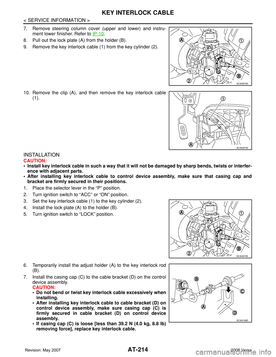
8. Pull out the lock plate (A) from the holder (B).
9. Remove the key interlock cable (1) from the key cylinder (2).
10. Remove the clip (A), and then remove the key interlock cable
(1).
INSTALLATION
CAUTION:
• Install key interlock cable in such a way that it will not be damaged by sharp bends, twists or interfer-
ence with adjacent parts.
• After installing key interlock cable to control device assembly, make sure that casing cap and
bracket are firmly secured in their positions.
1. Place the selector lever in the “P” position.
2. Turn ignition switch to “ACC” or “ON” position.
3. Set the key interlock cable (1) to the key cylinder (2).
4. Install the lock plate (A) to the holder (B).
5. Turn ignition switch to “LOCK” position.
6. Temporarily install the adjust holder (A) to the key interlock rod
(B).
7. Install the casing cap (C) to the cable bracket (D) on the control
device assembly.
CAUTION:
• Do not bend or twist key interlock cable excessively when
installing.
• After installing key interlock cable to cable bracket (D) on
control device assembly, make sure casing cap (C) is
firmly secured in cable bracket (D) on control device
assembly.
• If casing cap (C) is loose [less than 39.2 N (4.0 kg, 8.8 lb)
removing force], replace key interlock cable.
SCIA6976E
SCIA6973E
SCIA6976E
SCIA6188E
Page 227 of 2771
KEY INTERLOCK CABLE
AT-215
< SERVICE INFORMATION >
D
E
F
G
H
I
J
K
L
MA
B
AT
N
O
P
8. Slide the slider (A) toward the key interlock rod (D) while press-
ing the pull lock (B) down to securely connect the adjust holder
(C) with the key interlock rod (D).
CAUTION:
• Do not press tabs when holding slider (A).
• Do not apply any side to side force to key interlock rod (D)
when sliding slider (A).
9. Secure the key interlock cable (1) with the clip (A).
10. Install steering column cover (upper and lower) and instrument
lower finisher. Refer to IP-10
.
11. Install the center console assembly. Refer to IP-10
.
12. Install the selector lever knob. Refer to AT-206, "
Selector Lever
Knob Removal and Installation".
13. Check shift lock system. Refer to AT-209, "
Description".
SCIA6978E
SCIA6973E
Page 234 of 2771
AT-222
< SERVICE INFORMATION >
ON-VEHICLE SERVICE
3. Disconnect revolution sensor harness connector.
4. Remove clip (A).
5. Remove revolution sensor (1) from A/T.
: Bolt (2)
6. Remove O-ring from revolution sensor (1)
Installation
Installation is in the reverse order of removal.
CAUTION:
• Do not reuse O-ring.
• Apply ATF to O-ring.
• Ensure revolution sensor harness is firmly secured with bolt.
(1): Revolution sensor
: Bolt (1)
Turbine Revolution Sensor (Power Train Revolution Sensor)INFOID:0000000001703369
COMPONENTS
REMOVAL AND INSTALLATION
Removal
1. Disconnect the battery negative terminal.
2. Remove air duct (inlet). Refer to EM-16
.
WCIA0655E
WCIA0656E
1. A/T 2. O-ring 3. Turbine revolution sensor (power
train revolution sensor)
SCIA8020E
Page 239 of 2771

TRANSAXLE ASSEMBLY
AT-227
< SERVICE INFORMATION >
D
E
F
G
H
I
J
K
L
MA
B
AT
N
O
P
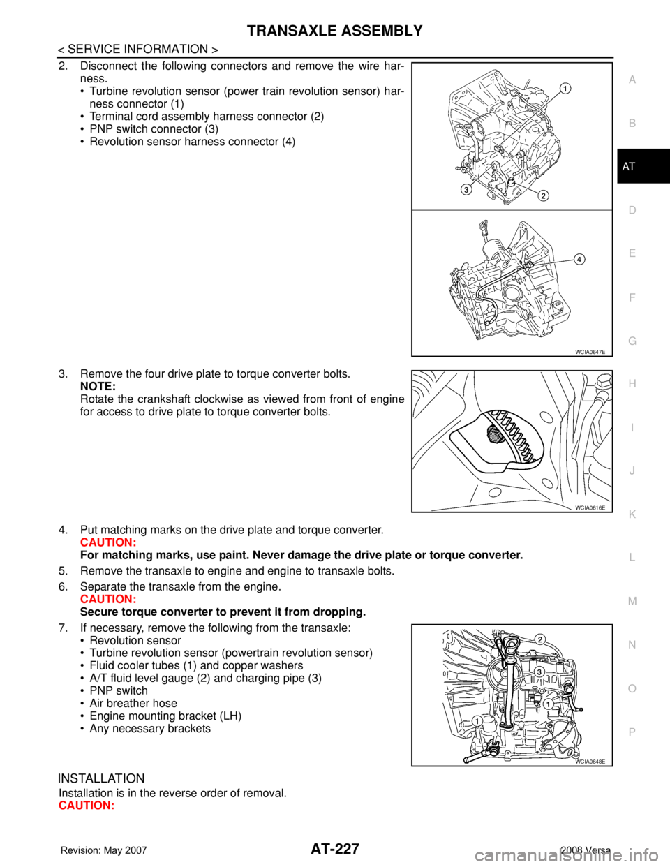
2. Disconnect the following connectors and remove the wire har-
ness.
• Turbine revolution sensor (power train revolution sensor) har-
ness connector (1)
• Terminal cord assembly harness connector (2)
• PNP switch connector (3)
• Revolution sensor harness connector (4)
3. Remove the four drive plate to torque converter bolts.
NOTE:
Rotate the crankshaft clockwise as viewed from front of engine
for access to drive plate to torque converter bolts.
4. Put matching marks on the drive plate and torque converter.
CAUTION:
For matching marks, use paint. Never damage the drive plate or torque converter.
5. Remove the transaxle to engine and engine to transaxle bolts.
6. Separate the transaxle from the engine.
CAUTION:
Secure torque converter to prevent it from dropping.
7. If necessary, remove the following from the transaxle:
• Revolution sensor
• Turbine revolution sensor (powertrain revolution sensor)
• Fluid cooler tubes (1) and copper washers
• A/T fluid level gauge (2) and charging pipe (3)
• PNP switch
• Air breather hose
• Engine mounting bracket (LH)
• Any necessary brackets
INSTALLATION
Installation is in the reverse order of removal.
CAUTION:
WCIA0647E
WCIA0616E
WCIA0648E
Page 240 of 2771

AT-228
< SERVICE INFORMATION >
TRANSAXLE ASSEMBLY
• When replacing an engine or transmission you must make sure any dowels are installed correctly
during re-assembly.
• Improper alignment caused by missing dowels may cause vibration, oil leaks or breakage of drive
train components.
• Do not reuse O-rings and copper washers. Refer to "COMPONENTS".
• When turning crankshaft, turn it clockwise as viewed from the front of the engine.
• When tightening the bolts for the torque converter while securing the crankshaft pulley bolt, be sure
to confirm the tightening torque of the crankshaft pulley bolt. Refer to EM-37
.
• After converter is installed to drive plate, rotate crankshaft several turns to check that transaxle
rotates freely without binding.
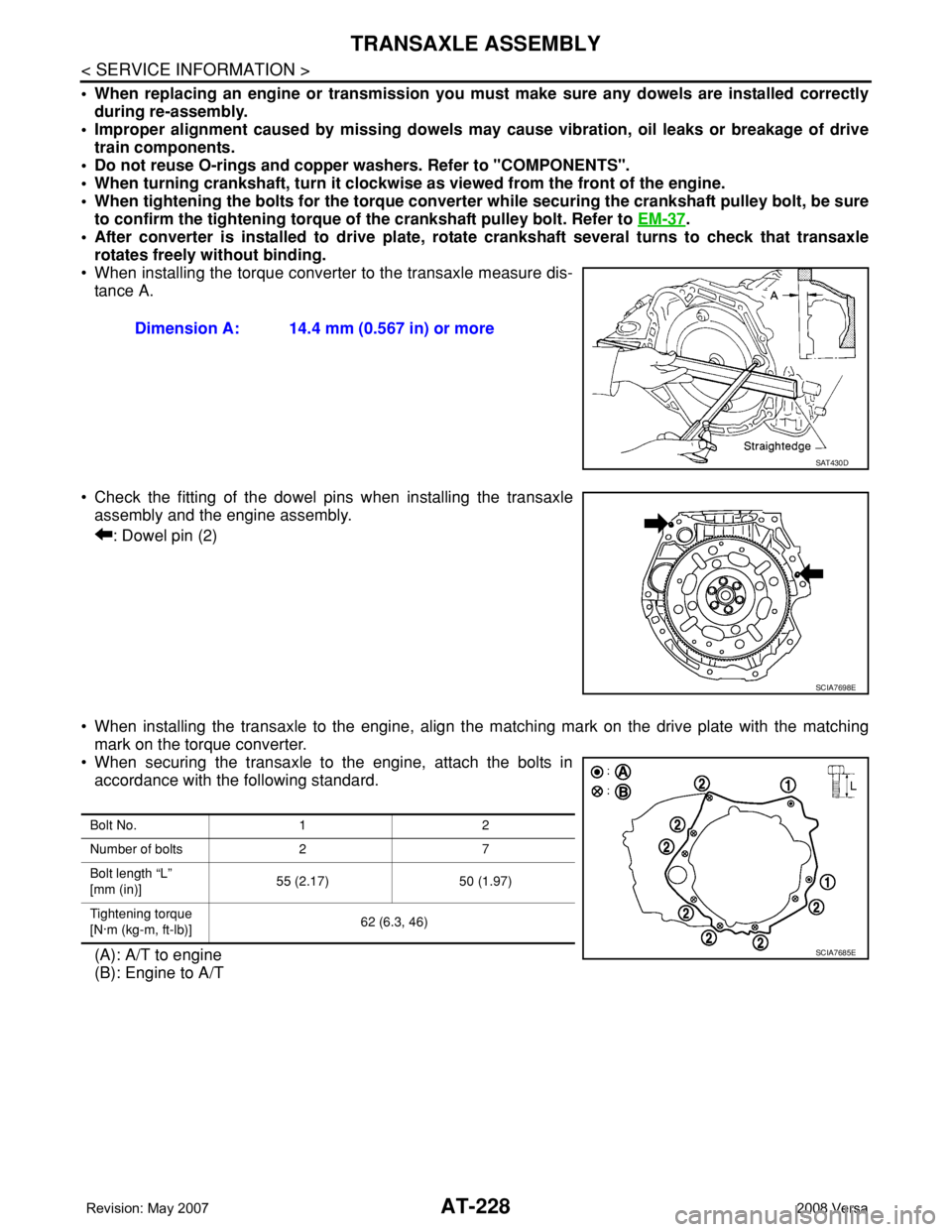
• When installing the torque converter to the transaxle measure dis-
tance A.
• Check the fitting of the dowel pins when installing the transaxle
assembly and the engine assembly.
: Dowel pin (2)
• When installing the transaxle to the engine, align the matching mark on the drive plate with the matching
mark on the torque converter.
• When securing the transaxle to the engine, attach the bolts in
accordance with the following standard.
(A): A/T to engine
(B): Engine to A/TDimension A: 14.4 mm (0.567 in) or more
SAT430D
SCIA7698E
Bolt No. 1 2
Number of bolts 2 7
Bolt length “L”
[mm (in)]55 (2.17) 50 (1.97)
Tightening torque
[N·m (kg-m, ft-lb)]62 (6.3, 46)
SCIA7685E
Page 259 of 2771
DISASSEMBLY
AT-247
< SERVICE INFORMATION >
D
E
F
G
H
I
J
K
L
MA
B
AT
N
O
P
d. Remove bearing race (1) and thrust washer (2) from oil pump
assembly (3).
30. Remove brake band according to the following procedures.
a. Loosen lock nut (1), and then remove anchor end pin (2) and
lock nut (1) as a set from transaxle case.
b. Remove brake band from transaxle case.
•To prevent brake linings from cracking or peeling, do not
stretch the flexible band unnecessarily. When removing
brake band, always secure it with a clip as shown in the
figure.
Leave the clip in position after removing brake band.
SCIA6957E
SCIA6037J
SAT038D
SAT039D
Page 352 of 2771
AT-340
< SERVICE INFORMATION >
ASSEMBLY
Ensure revolution sensor harness is firmly secured with
bolt.
(1): Revolution sensor
: Bolt (1)
35. Install torque converter.
a. Pour ATF into torque converter.
•Approximately 1 liter (1 US qt, 7/8 Imp pt) of fluid is
required for a new torque converter.
•When reusing old torque converter, add the same amount
of ATF as was drained.
b. Install torque converter while aligning notches of torque con-
verter with notches of oil pump.
c. Measure distance “A” to make sure that torque converter is in
proper position.
SCIA6518J
SAT428DA
SAT429D
Distance “A”: 14.4 mm (0.567 in) or more
SAT430D
Page 393 of 2771

AV-34
< SERVICE INFORMATION >
AUDIO
Sound Is Not Heard from Subwoofer (Premium System)
INFOID:0000000001704673
1.CHECK FUSE
Check that the following fuse is not blown.
OK or NG
OK >> GO TO 2.
NG >> If fuse is blown, be sure to eliminate cause of blown fuse before installing new fuse. Refer to PG-
3 .
2.EQ SETTING CHECK
1. Ensure that subwoofer amp. connector B29 and audio unit harness connectors M43, M44 and M45 are
securely connected.
2. Turn the ignition switch to the ACC position.
3. Press the "AUDIO", "AUX", and "TUNE DOWN" switches simultaneously, the current EQ Setting will be
displayed.
Is "Woofer On" displayed?
YES >> GO TO 3.
NO >> Disconnect all audio unit harness connectors and wait for 2 minutes in order to reset the audio
unit. Reconnect audio unit connectors M44 and M45 first followed by M43 last. Repeat Steps 1
through 3 to confirm that "Woofer On" is now displayed.
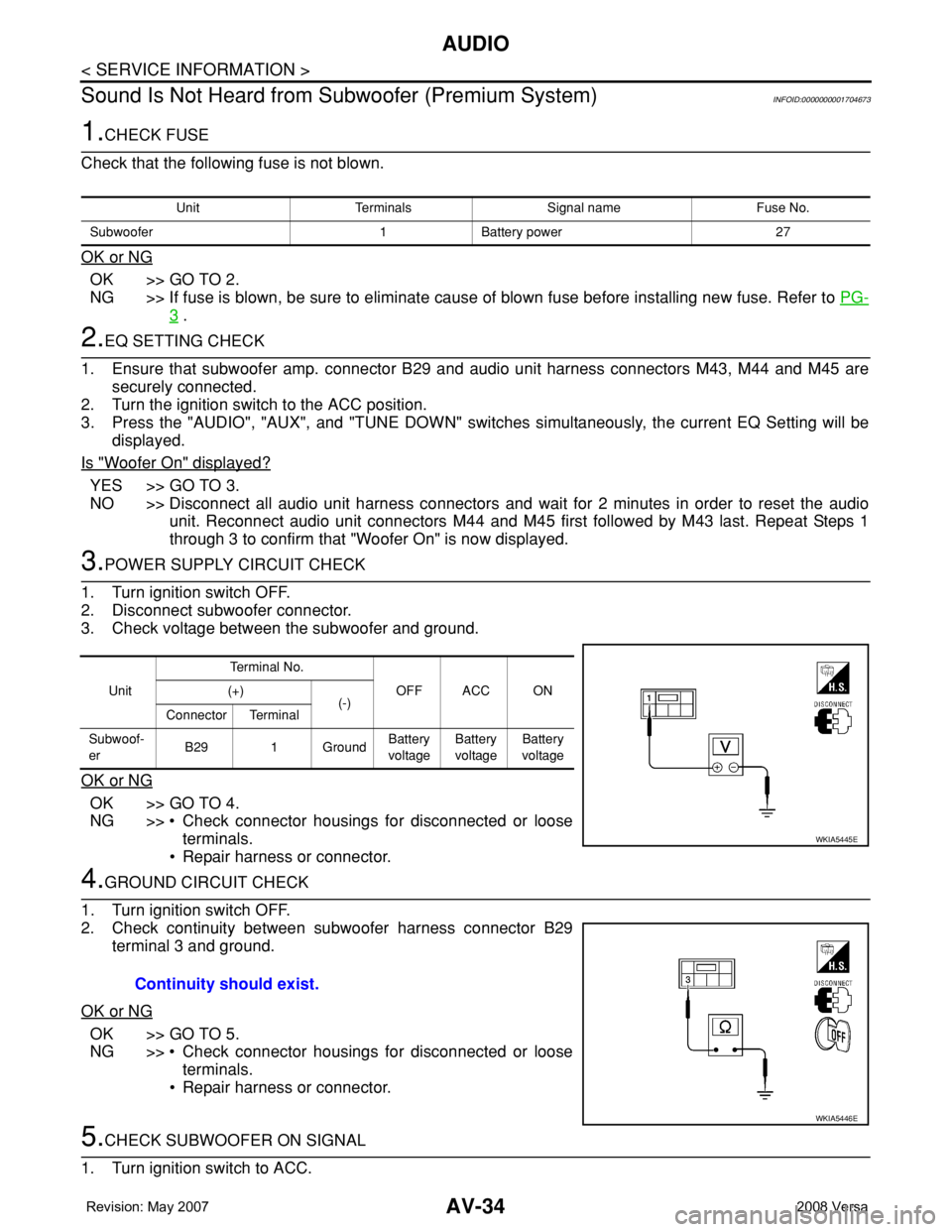
3.POWER SUPPLY CIRCUIT CHECK
1. Turn ignition switch OFF.
2. Disconnect subwoofer connector.
3. Check voltage between the subwoofer and ground.
OK or NG
OK >> GO TO 4.
NG >> • Check connector housings for disconnected or loose
terminals.
• Repair harness or connector.
4.GROUND CIRCUIT CHECK
1. Turn ignition switch OFF.
2. Check continuity between subwoofer harness connector B29
terminal 3 and ground.
OK or NG
OK >> GO TO 5.
NG >> • Check connector housings for disconnected or loose
terminals.
• Repair harness or connector.
5.CHECK SUBWOOFER ON SIGNAL
1. Turn ignition switch to ACC.
Unit Terminals Signal name Fuse No.
Subwoofer 1 Battery power 27
UnitTe r m i n a l N o .
OFF ACC ON (+)
(-)
Connector Terminal
Subwoof-
erB29 1 GroundBattery
voltageBattery
voltageBattery
voltage
WKIA5445E
Continuity should exist.
WKIA5446E