2008 NISSAN TIIDA connector d2
[x] Cancel search: connector d2Page 2726 of 2771
WT-18
< SERVICE INFORMATION >
TROUBLE DIAGNOSIS FOR SELF-DIAGNOSTIC ITEMS
TROUBLE DIAGNOSIS FOR SELF-DIAGNOSTIC ITEMS
Data from Transmitter Not Being ReceivedINFOID:0000000001703763
MALFUNCTION CODE NO. 21, 22, 23 or 24 (DTC C1708, C1709, C1710 or C1711)
1.CHECK BCM
Drive for several minutes. Check all tire pressures with CONSULT-III.
Are all tire pressures displayed as 0 kPa?
YES >> GO TO 2.
NO >> GO TO 3.
2.CHECK REMOTE KEYLESS ENTRY RECEIVER CONNECTOR
Check remote keyless entry receiver connector for damage or loose connections.
OK or NG
OK >> Replace BCM, then GO TO 3. Refer to BCS-18, "Removal and Installation of BCM".
NG >> Repair or replace remote keyless entry receiver connector.
3.PERFORM ID REGISTRATION
Carry out ID registration of all transmitters. Refer to WT-11, "
ID Registration Procedure".
Is there a tire that cannot register ID?
YES >> Replace transmitter of the tire, then GO TO 5. Refer to WT-23, "Transmitter (Pressure Sensor)".
NO >> GO TO 4.
4.DRIVE VEHICLE
1. Drive at a speed of 40 km/h (25 MPH) or more for several minutes without stopping.
2. Check all tire pressures with CONSULT-III within 15 minutes after vehicle speed becomes 17 km/h (11
MPH).
Does
“DATA MONITOR ITEM” display tire pressure as normal without any warning lamp?
YES >> Inspection End.
NO >> GO TO 5.
5.ID REGISTRATION AND VEHICLE DRIVING
1. Carry out ID registration of all transmitters. Refer to WT-11, "
ID Registration Procedure".
2. Drive at a speed of 40 km/h (25 MPH) or more for 3 minutes, and then drive the vehicle at any speed for
10 minutes.
3. Check all tire pressures with CONSULT-III within 5 minutes.
Does
“DATA MONITOR ITEM” display tire pressure as normal without any warning lamp?
YES >> Inspection End.
NO >> GO TO the inspection applicable to DTC.
Transmitter MalfunctionINFOID:0000000001703764
MALFUNCTION CODE NO. 31, 32, 33, 34, 41, 42, 43, 44, 45, 46, 47 or 48 (DTC C1712, C1713,
C1714, C1715, C1720, C1721, C1722, C1723, C1724, C1725, C1726 or C1727)
1.PERFORM ID REGISTRATION
1. Carry out ID registration of all transmitters. Refer to WT-11, "
ID Registration Procedure".
2. Drive at a speed of 40 km/h (25 MPH) or more for 3 minutes, and then drive the vehicle at any speed for
10 minutes.
>> GO TO 2.
2.REPLACE TRANSMITTER
1. Check low tire pressure warning lamp again for flashing, replace malfunctioning transmitter. Refer to WT-
23, "Transmitter (Pressure Sensor)".
2. Carry out ID registration of all transmitters. Refer to WT-11, "
ID Registration Procedure".
Page 2728 of 2771
WT-20
< SERVICE INFORMATION >
TROUBLE DIAGNOSIS FOR SYMPTOMS
TROUBLE DIAGNOSIS FOR SYMPTOMS
Low Tire Pressure Warning Lamp Does Not Come On When Ignition Switch Is Turned
On
INFOID:0000000001703767
DIAGNOSTIC PROCEDURE
1.SELF-DIAGNOSTIC RESULT CHECK
Using CONSULT-III, check display contents in self-diagnostic results.
Is "CAN COMM CIRCUIT" displayed in the self-diagnosis display items?
YES >> Malfunction in CAN communication system. GO TO LAN-12, "CAN Diagnosis with CONSULT-
III".
NO >> GO TO 2.
2.CHECK COMBINATION METER
Check combination meter operation. Refer to DI-11, "
Self-Diagnosis Mode of Combination Meter".
Inspection results OK?
OK >> GO TO 3.
NG >> Replace combination meter. Refer to IP-11, "
Removal and Installation".
3.CHECK LOW TIRE PRESSURE WARNING LAMP
Disconnect BCM harness connector.
Does the low tire pressure warning lamp activate?
YES >> Replace BCM. Refer to BCS-18, "Removal and Installation of BCM".
NO >> Check combination meter operation. Refer to DI-11, "
Self-Diagnosis Mode of Combination
Meter".
Low Tire Pressure Warning Lamp Stays On When Ignition Switch Is Turned On
INFOID:0000000001703768
DIAGNOSTIC PROCEDURE
1.CHECK BCM CONNECTORS
1. Turn ignition switch OFF.
2. Disconnect BCM harness connectors M18 and M20.
3. Check terminals for damage or loose connections.
Inspection results OK?
OK >> GO TO 2.
NG >> Repair or replace damaged parts.
2.CHECK BCM POWER SUPPLY CIRCUIT (BAT)
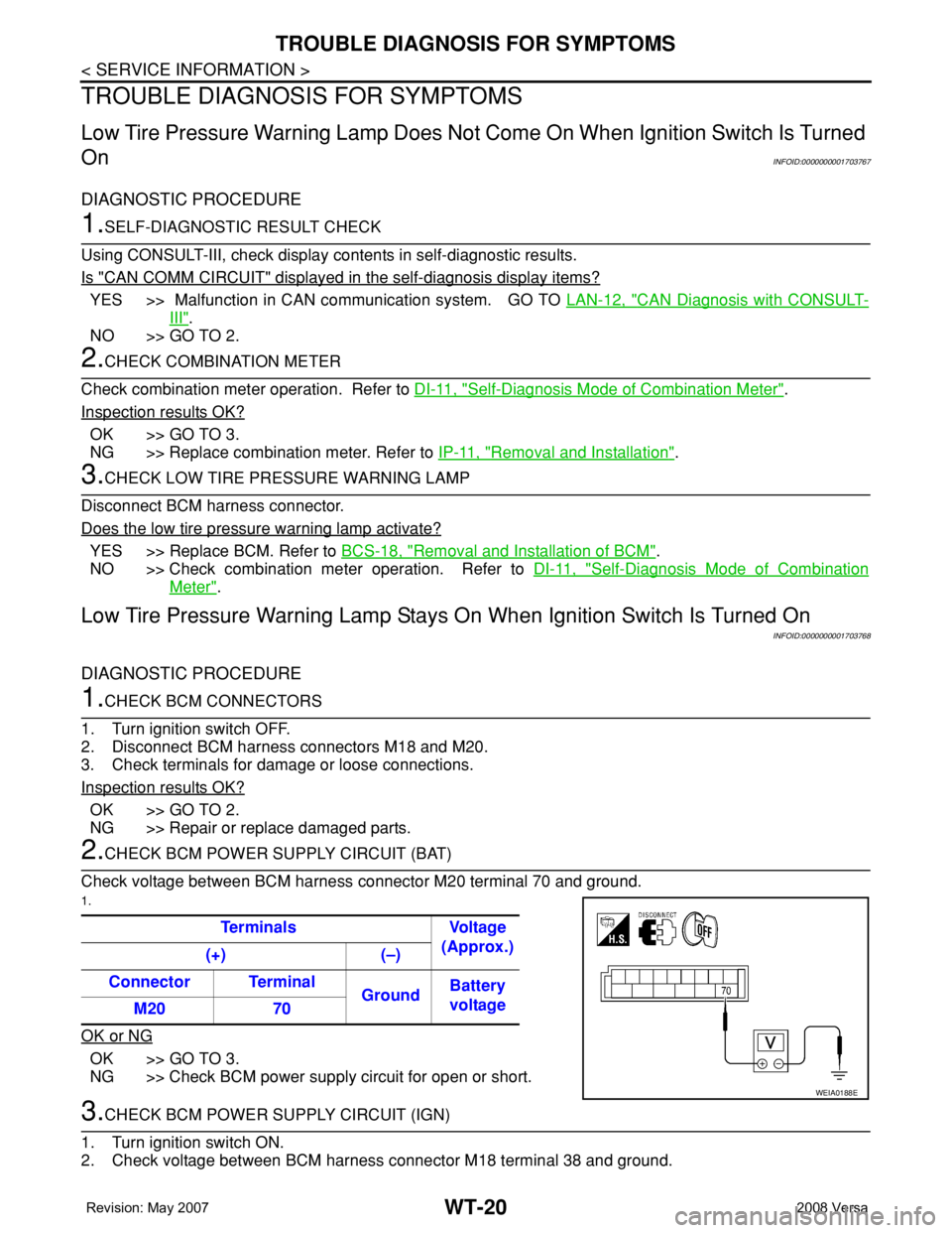
Check voltage between BCM harness connector M20 terminal 70 and ground.
1.
OK or NG
OK >> GO TO 3.
NG >> Check BCM power supply circuit for open or short.
3.CHECK BCM POWER SUPPLY CIRCUIT (IGN)
1. Turn ignition switch ON.
2. Check voltage between BCM harness connector M18 terminal 38 and ground.Terminals Voltage
(Approx.)
(+) (–)
Connector Terminal
GroundBattery
voltage
M20 70
WEIA0188E
Page 2729 of 2771
TROUBLE DIAGNOSIS FOR SYMPTOMS
WT-21
< SERVICE INFORMATION >
C
D
F
G
H
I
J
K
L
MA
B
WT
N
O
P
OK or NG
OK >> GO TO 4.
NG >> Check BCM power supply circuit for open or short.
4.CHECK BCM GROUND CIRCUIT
1. Turn ignition switch OFF.
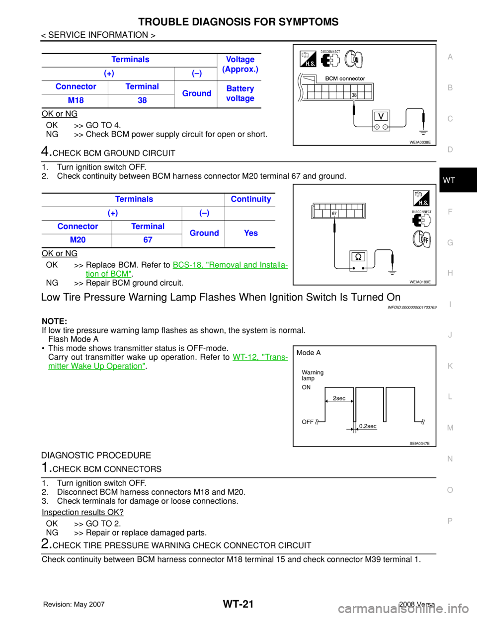
2. Check continuity between BCM harness connector M20 terminal 67 and ground.
OK or NG
OK >> Replace BCM. Refer to BCS-18, "Removal and Installa-
tion of BCM".
NG >> Repair BCM ground circuit.
Low Tire Pressure Warning Lamp Flashes When Ignition Switch Is Turned On
INFOID:0000000001703769
NOTE:
If low tire pressure warning lamp flashes as shown, the system is normal.
Flash Mode A
• This mode shows transmitter status is OFF-mode.
Carry out transmitter wake up operation. Refer to WT-12, "
Trans-
mitter Wake Up Operation".
DIAGNOSTIC PROCEDURE
1.CHECK BCM CONNECTORS
1. Turn ignition switch OFF.
2. Disconnect BCM harness connectors M18 and M20.
3. Check terminals for damage or loose connections.
Inspection results OK?
OK >> GO TO 2.
NG >> Repair or replace damaged parts.
2.CHECK TIRE PRESSURE WARNING CHECK CONNECTOR CIRCUIT
Check continuity between BCM harness connector M18 terminal 15 and check connector M39 terminal 1. Terminals Voltage
(Approx.)
(+) (–)
Connector Terminal
GroundBattery
voltage
M18 38
WEIA0038E
Terminals Continuity
(+) (–)
Connector Terminal
Ground Yes
M20 67
WEIA0189E
SEIA0347E
Page 2730 of 2771
WT-22
< SERVICE INFORMATION >
TROUBLE DIAGNOSIS FOR SYMPTOMS
OK or NG
OK >> Replace BCM. Refer to BCS-18, "Removal and Installa-
tion of BCM".
NG >> Repair or replace harness connector.
Hazard Warning Lamps Flash When Ignition Switch Is Turned OnINFOID:0000000001703770
DIAGNOSTIC PROCEDURE
1.CHECK BCM GROUND CIRCUIT
1. Turn ignition switch OFF.
2. Disconnect BCM harness connector M20.
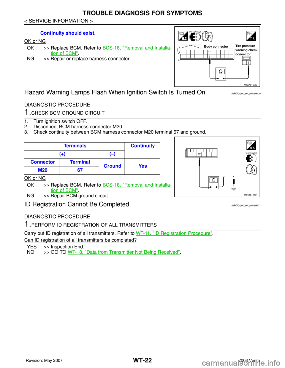
3. Check continuity between BCM harness connector M20 terminal 67 and ground.
OK or NG
OK >> Replace BCM. Refer to BCS-18, "Removal and Installa-
tion of BCM".
NG >> Repair BCM ground circuit.
ID Registration Cannot Be CompletedINFOID:0000000001703771
DIAGNOSTIC PROCEDURE
1.PERFORM ID REGISTRATION OF ALL TRANSMITTERS
Carry out ID registration of all transmitters. Refer to WT-11, "
ID Registration Procedure".
Can ID registration of all transmitters be completed?
YES >> Inspection End.
NO >> GO TO WT-18, "
Data from Transmitter Not Being Received". Continuity should exist.
WEIA0127E
Terminals Continuity
(+) (–)
Connector Terminal
Ground Yes
M20 67
WEIA0189E
Page 2734 of 2771

WW-1
ELECTRICAL
C
D
E
F
G
H
I
J
L
M
SECTION WW
A
B
WW
N
O
P
CONTENTS
WIPER, WASHER & HORN
SERVICE INFORMATION ............................2
PRECAUTION .....................................................2
Precaution for Supplemental Restraint System
(SRS) "AIR BAG" and "SEAT BELT PRE-TEN-
SIONER" ...................................................................
2
Precaution for Procedure without Cowl Top Cover ......2
FRONT WIPER AND WASHER SYSTEM ..........3
Component Parts and Harness Connector Loca-
tion ............................................................................
3
System Description ...................................................3
CAN Communication System Description .................5
Schematic .................................................................6
Wiring Diagram - WIPER - ........................................7
Terminal and Reference Value for BCM ...................9
Terminal and Reference Value for IPDM E/R ...........9
How to Proceed with Trouble Diagnosis .................10
Preliminary Check ...................................................10
CONSULT-III Function (BCM) .................................10
CONSULT-III Function (IPDM E/R) .........................11
Front Wiper Does Not Operate ...............................12
Front Wiper Does Not Return to Stop Position (Af-
ter Front Wiper Operate for 10 Seconds, They
Stop for 20 Seconds, and After Repeating the Op-
eration Five Times, They Become Inoperative) ......
14
Only Front Wiper Low Does Not Operate ...............15
Only Front Wiper High Does Not Operate ...............16
Only Front Wiper Intermittent Does Not Operate ....17
Front Wiper Intermittent Operation Switch Posi-
tion Cannot Be Adjusted .........................................
17
Wiper Does Not Wipe When Front Washer Oper-
ates .........................................................................
18
Front Wiper Does Not Stop .....................................18
Removal and Installation of Front Wiper Arms ........18
Adjustment of Wiper Arm Stop Location .................19
Removal and Installation of Front Wiper Drive As-
sembly .....................................................................
19
Removal and Installation of Front Washer Nozzle ....20
Inspection for Washer Nozzle ..................................20
Washer Nozzle Adjustment .....................................21
Washer Tube Layout ...............................................21
Removal and Installation of Front Wiper and
Washer Switch .........................................................
22
Inspection of Front Wiper and Washer Switch Cir-
cuit ...........................................................................
22
Removal and Installation of Washer Tank ...............22
Removal and Installation of Front Washer Motor ....23
REAR WIPER AND WASHER SYSTEM ..........24
Component Parts and Harness Connector Loca-
tion ...........................................................................
24
System Description ..................................................24
Wiring Diagram - WIP/R - ........................................26
Terminal and Reference Value for BCM ..................27
How to Proceed with Trouble Diagnosis ..................27
Preliminary Check ...................................................28
CONSULT-III Function (BCM) .................................28
Rear Wiper Does Not Operate ................................28
Rear Wiper Stop Position Is Incorrect .....................29
Only Rear Wiper Does Not Operate ........................30
Only Rear Wiper Intermittent Does Not Operate .....31
Wiper Does Not Wipe When Rear Washer Oper-
ates ..........................................................................
31
Removal and Installation .........................................31
Washer Nozzle Adjustment .....................................34
POWER SOCKET .............................................35
Wiring Diagram - P/SCKT - .....................................35
Removal and Installation .........................................35
HORN ................................................................37
Wiring Diagram - HORN - ........................................37
Removal and Installation .........................................37
Page 2735 of 2771
WW-2
< SERVICE INFORMATION >
PRECAUTION
SERVICE INFORMATION
PRECAUTION
Precaution for Supplemental Restraint System (SRS) "AIR BAG" and "SEAT BELT
PRE-TENSIONER"
INFOID:0000000001704533
The Supplemental Restraint System such as “AIR BAG” and “SEAT BELT PRE-TENSIONER”, used along
with a front seat belt, helps to reduce the risk or severity of injury to the driver and front passenger for certain
types of collision. This system includes seat belt switch inputs and dual stage front air bag modules. The SRS
system uses the seat belt switches to determine the front air bag deployment, and may only deploy one front
air bag, depending on the severity of a collision and whether the front occupants are belted or unbelted.
Information necessary to service the system safely is included in the SRS and SB section of this Service Man-
ual.
WARNING:
• To avoid rendering the SRS inoperative, which could increase the risk of personal injury or death in
the event of a collision which would result in air bag inflation, all maintenance must be performed by
an authorized NISSAN/INFINITI dealer.
• Improper maintenance, including incorrect removal and installation of the SRS, can lead to personal
injury caused by unintentional activation of the system. For removal of Spiral Cable and Air Bag
Module, see the SRS section.
• Do not use electrical test equipment on any circuit related to the SRS unless instructed to in this
Service Manual. SRS wiring harnesses can be identified by yellow and/or orange harnesses or har-
ness connectors.
Precaution for Procedure without Cowl Top CoverINFOID:0000000001704534
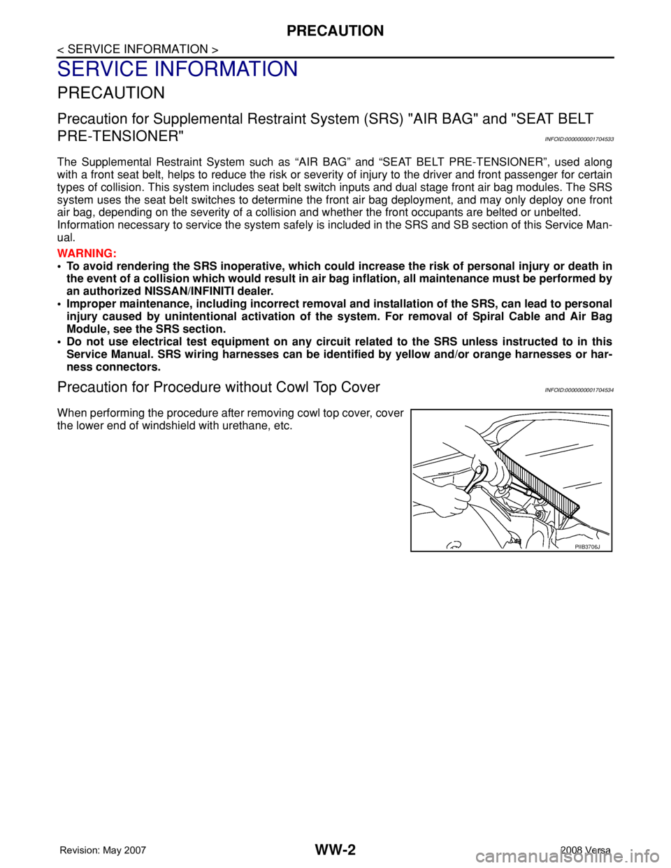
When performing the procedure after removing cowl top cover, cover
the lower end of windshield with urethane, etc.
PIIB3706J
Page 2736 of 2771
FRONT WIPER AND WASHER SYSTEM
WW-3
< SERVICE INFORMATION >
C
D
E
F
G
H
I
J
L
MA
B
WW
N
O
P
FRONT WIPER AND WASHER SYSTEM
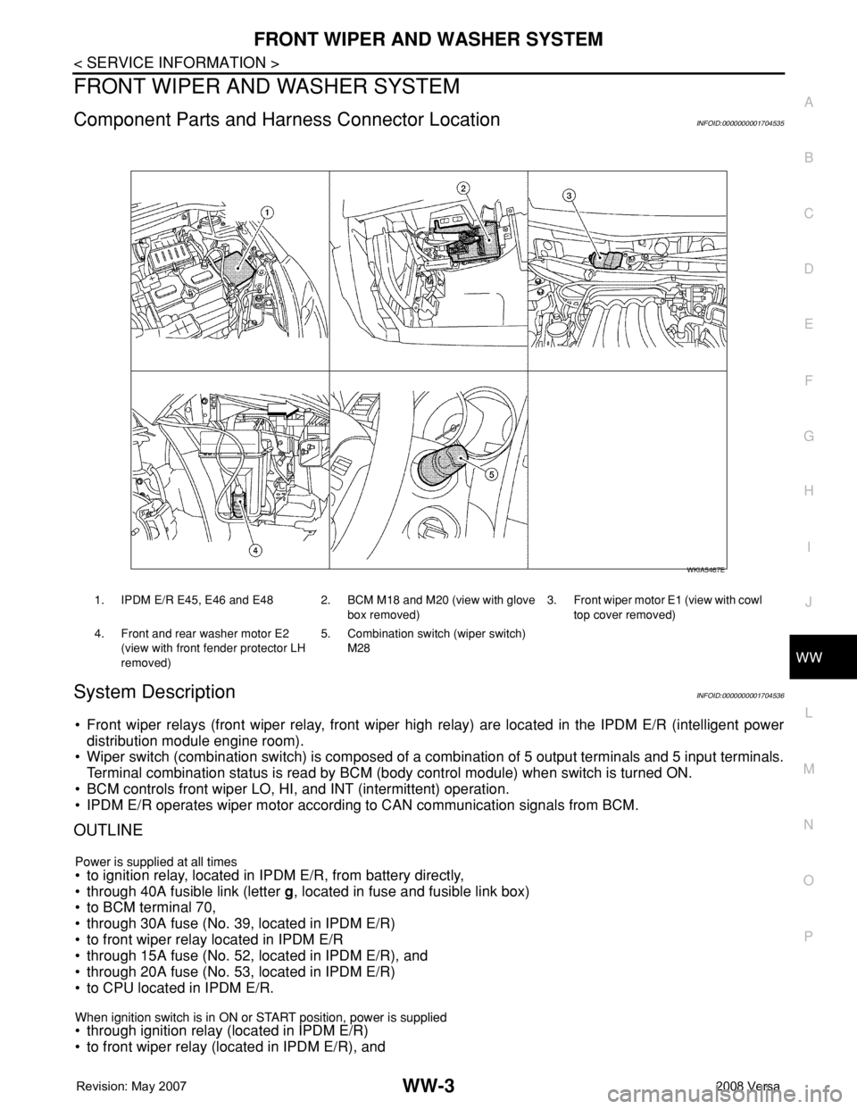
Component Parts and Harness Connector LocationINFOID:0000000001704535
System DescriptionINFOID:0000000001704536
• Front wiper relays (front wiper relay, front wiper high relay) are located in the IPDM E/R (intelligent power
distribution module engine room).
• Wiper switch (combination switch) is composed of a combination of 5 output terminals and 5 input terminals.
Terminal combination status is read by BCM (body control module) when switch is turned ON.
• BCM controls front wiper LO, HI, and INT (intermittent) operation.
• IPDM E/R operates wiper motor according to CAN communication signals from BCM.
OUTLINE
Power is supplied at all times• to ignition relay, located in IPDM E/R, from battery directly,
• through 40A fusible link (letter g, located in fuse and fusible link box)
• to BCM terminal 70,
• through 30A fuse (No. 39, located in IPDM E/R)
• to front wiper relay located in IPDM E/R
• through 15A fuse (No. 52, located in IPDM E/R), and
• through 20A fuse (No. 53, located in IPDM E/R)
• to CPU located in IPDM E/R.
When ignition switch is in ON or START position, power is supplied • through ignition relay (located in IPDM E/R)
• to front wiper relay (located in IPDM E/R), and
1. IPDM E/R E45, E46 and E48 2. BCM M18 and M20 (view with glove
box removed)3. Front wiper motor E1 (view with cowl
top cover removed)
4. Front and rear washer motor E2
(view with front fender protector LH
removed)5. Combination switch (wiper switch)
M28
WKIA5467E
Page 2745 of 2771
WW-12
< SERVICE INFORMATION >
FRONT WIPER AND WASHER SYSTEM
Front Wiper Does Not Operate
INFOID:0000000001704546
CAUTION:
• During IPDM E/R fail-safe control, front wipers may not operate. Refer to PG-16, "
System Descrip-
tion" in “PG IPDM E/R” to make sure that it is not in fail-safe status.
1.ACTIVE TEST
With CONSULT-lIl
1. Select “IPDM E/R” on CONSULT-III, and select “ACTIVE TEST” on “SELECT DIAG MODE” screen.
2. Select “FRONT WIPER” on “SELECT TEST ITEM” screen.
3. Touch “LO” or “HI” screen.
Without CONSULT-lIl
Start up auto active test. Refer to PG-19, "
Auto Active Test" .
Does front wiper operate normally?
YES >> GO TO 2.
NO >> GO TO 4.
2.CHECK CIRCUIT BETWEEN COMBINATION SWITCH AND BCM
With CONSULT-llI
1. Select “BCM” on CONSULT-III, and select “WIPER” on “SELECT TEST ITEM” screen.
2. Select “DATA MONITOR” on “SELECT DIAG MODE” screen. Make sure that “FR WIPER INT”, “FR
WIPER LOW”, and “FR WIPER HI” turn ON-OFF according to wiper switch operation.
Without CONSULT-lIl
Refer to LT-63, "
Combination Switch Inspection" .
OK or NG
OK >> GO TO 3.
NG >> Check combination switch (wiper switch). Refer to LT-63, "
Combination Switch Inspection" .
3.CHECK CIRCUIT BETWEEN IPDM E/R AND BCM
Select “BCM” on CONSULT-III, and perform self-diagnosis for “BCM”.
Displayed self
-diagnosis results
NO DTC>>Replace BCM. Refer to BCS-18, "Removal and Installation of BCM" .
CAN COMM CIRCUIT>>Check CAN communication line of BCM. Refer to BCS-17, "
CAN Communication
Inspection Using CONSULT-III (Self-Diagnosis)" .
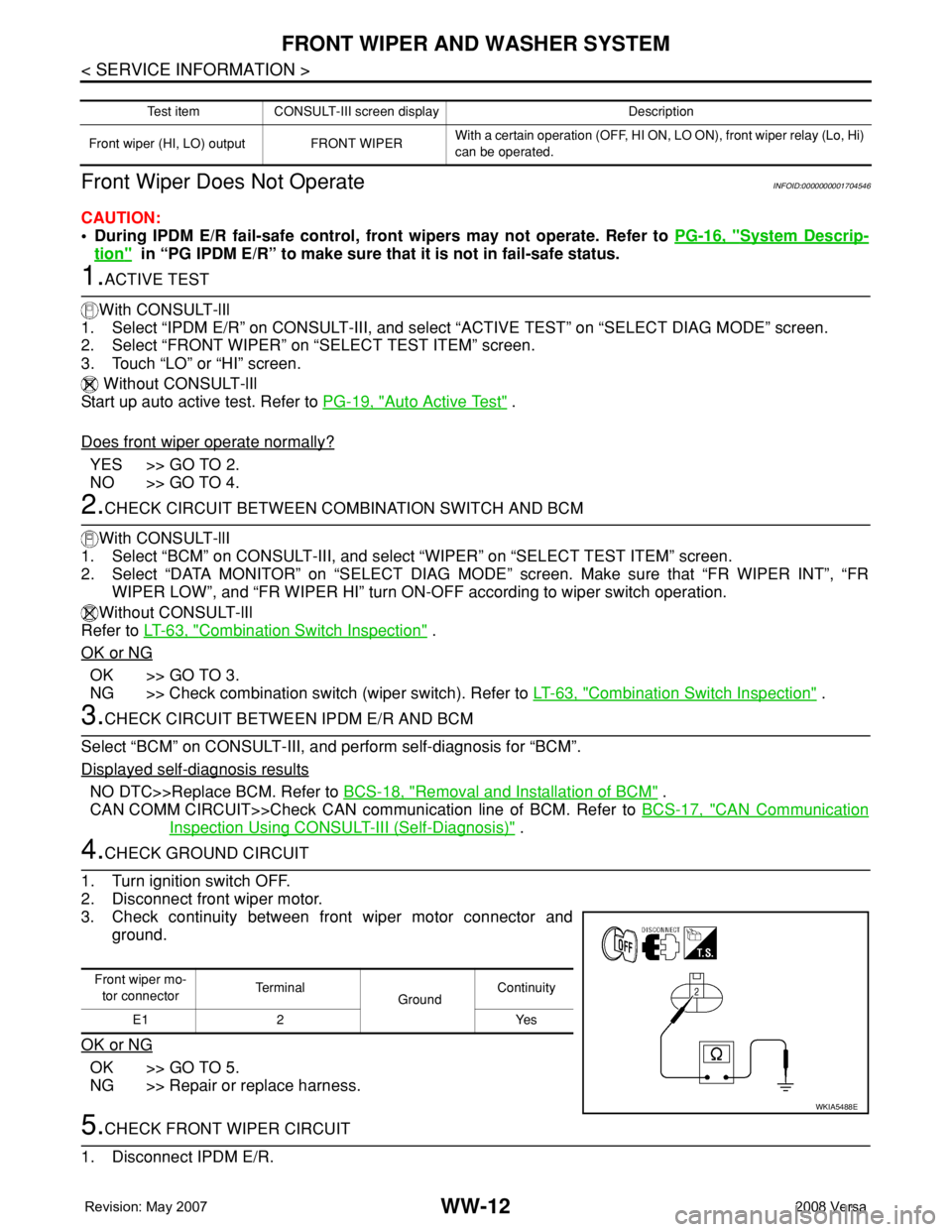
4.CHECK GROUND CIRCUIT
1. Turn ignition switch OFF.
2. Disconnect front wiper motor.
3. Check continuity between front wiper motor connector and
ground.
OK or NG
OK >> GO TO 5.
NG >> Repair or replace harness.
5.CHECK FRONT WIPER CIRCUIT
1. Disconnect IPDM E/R.
Test item CONSULT-III screen display Description
Front wiper (HI, LO) output FRONT WIPERWith a certain operation (OFF, HI ON, LO ON), front wiper relay (Lo, Hi)
can be operated.
Front wiper mo-
tor connectorTe r m i n a l
GroundContinuity
E1 2 Yes
WKIA5488E