2008 NISSAN TIIDA connector d2
[x] Cancel search: connector d2Page 2746 of 2771
FRONT WIPER AND WASHER SYSTEM
WW-13
< SERVICE INFORMATION >
C
D
E
F
G
H
I
J
L
MA
B
WW
N
O
P
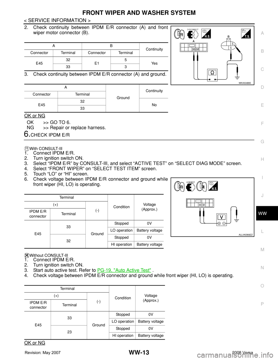
2. Check continuity between IPDM E/R connector (A) and front
wiper motor connector (B).
3. Check continuity between IPDM E/R connector (A) and ground.
OK or NG
OK >> GO TO 6.
NG >> Repair or replace harness.
6.CHECK IPDM E/R
With CONSULT-lIl
1. Connect IPDM E/R.
2. Turn ignition switch ON.
3. Select “IPDM E/R” by CONSULT-III, and select “ACTIVE TEST” on “SELECT DIAG MODE” screen.
4. Select “FRONT WIPER” on “SELECT TEST ITEM” screen.
5. Touch “LO” or “HI” screen.
6. Check voltage between IPDM E/R connector and ground while
front wiper (HI, LO) is operating.
Without CONSULT-llI1. Connect IPDM E/R.
2. Turn ignition switch ON.
3. Start auto active test. Refer to PG-19, "
Auto Active Test" .
4. Check voltage between IPDM E/R connector and ground while front wiper (HI, LO) is operating.
OK or NG
AB
Continuity
Connector Terminal Connector Terminal
E4532
E15
Ye s
33 3
A
GroundContinuity
Connector Terminal
E4532
No
33
WKIA5489E
Te r m i n a l
ConditionVo l ta g e
(Approx.) (+)
(-)
IPDM E/R
connectorTe r m i n a l
E4533
GroundStopped 0V
LO operation Battery voltage
32Stopped 0V
HI operation Battery voltage
Te r m i n a l
ConditionVol tag e
(Approx.) (+)
(-)
IPDM E/R
connectorTe r m i n a l
E4533
GroundStopped 0V
LO operation Battery voltage
23Stopped 0V
HI operation Battery voltage
ALLIA0368ZZ
Page 2747 of 2771
WW-14
< SERVICE INFORMATION >
FRONT WIPER AND WASHER SYSTEM
OK >> Replace front wiper motor. Refer to WW-19, "Removal and Installation of Front Wiper Drive
Assembly" .
NG >> Replace IPDM E/R. Refer to PG-26, "
Removal and Installation of IPDM E/R" .
Front Wiper Does Not Return to Stop Position (After Front Wiper Operate for 10 Sec-
onds, They Stop for 20 Seconds, and After Repeating the Operation Five Times, They
Become Inoperative)
INFOID:0000000001704547
CAUTION:
• When auto-stop signal has not varied for 10 seconds or longer while IPDM E/R is operating front wip-
ers, IPDM E/R considers that front wipers are locked, and stops wiper output. That causes this symp-
tom.
• This status can be checked by “DATA MONITOR” of “IPDM E/R” on which “WIPER PROT” item
shows “BLOCK”.
1.CHECK FRONT WIPER STOP SIGNAL
With CONSULT-lIl
Select “IPDM E/R” on CONSULT-III. With “DATA MONITOR”, make sure that “WIP AUTO STOP” turns “ACT
P” - “STOP P” linked with wiper operation.
Without CONSULT-llI
GO TO 2.
OK or NG
OK >> Replace IPDM E/R. Refer to PG-26, "Removal and Installation of IPDM E/R" .
NG >> GO TO 2.
2.CHECK IPDM E/R
1. Turn ignition switch ON.
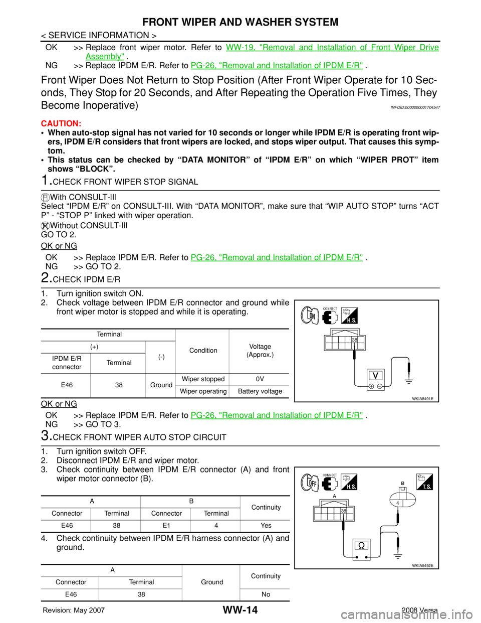
2. Check voltage between IPDM E/R connector and ground while
front wiper motor is stopped and while it is operating.
OK or NG
OK >> Replace IPDM E/R. Refer to PG-26, "Removal and Installation of IPDM E/R" .
NG >> GO TO 3.
3.CHECK FRONT WIPER AUTO STOP CIRCUIT
1. Turn ignition switch OFF.
2. Disconnect IPDM E/R and wiper motor.
3. Check continuity between IPDM E/R connector (A) and front
wiper motor connector (B).
4. Check continuity between IPDM E/R harness connector (A) and
ground.
Te r m i n a l
ConditionVo l ta g e
(Approx.) (+)
(-)
IPDM E/R
connectorTe r m i n a l
E46 38 GroundWiper stopped 0V
Wiper operating Battery voltage
WKIA5491E
AB
Continuity
Connector Terminal Connector Terminal
E46 38 E1 4 Yes
A
GroundContinuity
Connector Terminal
E46 38 No
WKIA5492E
Page 2748 of 2771
FRONT WIPER AND WASHER SYSTEM
WW-15
< SERVICE INFORMATION >
C
D
E
F
G
H
I
J
L
MA
B
WW
N
O
P
OK or NG
OK >> Replace front wiper motor. Refer to WW-19, "Removal and Installation of Front Wiper Drive
Assembly" .
NG >> Repair or replace harness.
Only Front Wiper Low Does Not OperateINFOID:0000000001704548
1.ACTIVE TEST
With CONSULT-lIl
1. Select “IPDM E/R” on CONSULT-III, and select “ACTIVE TEST” on “SELECT DIAG MODE” screen.
2. Select “FRONT WIPER” on “SELECT TEST ITEM” screen.
3. Touch “LO” screen.
Without CONSULT-lIl
Start auto active test. Refer to PG-19, "
Auto Active Test" .
Does front wiper operate normally?
YES >> Refer to LT-63, "Combination Switch Inspection" .
NO >> GO TO 2.
2.CHECK FRONT WIPER MOTOR CIRCUIT
1. Turn ignition switch OFF.
2. Disconnect IPDM E/R and front wiper motor.
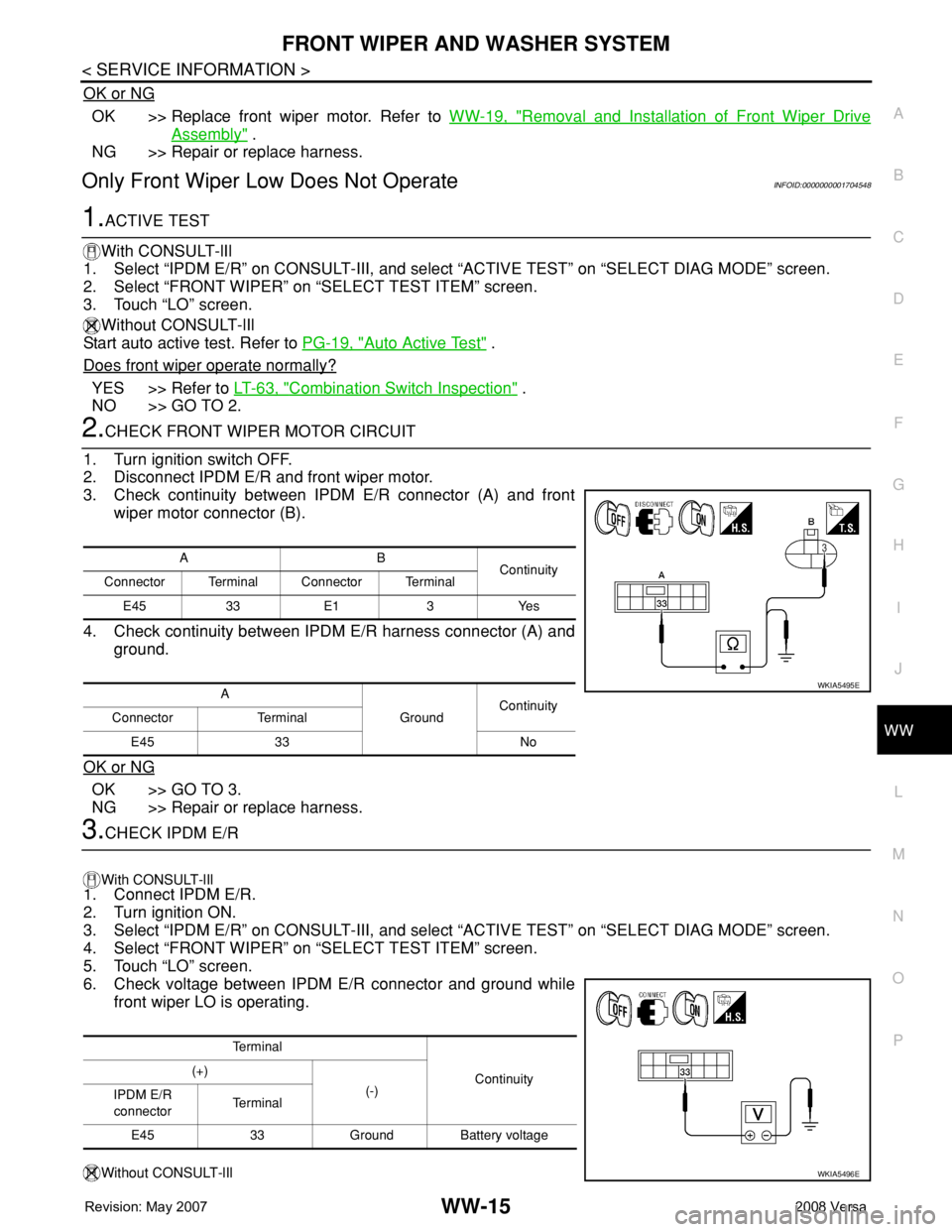
3. Check continuity between IPDM E/R connector (A) and front
wiper motor connector (B).
4. Check continuity between IPDM E/R harness connector (A) and
ground.
OK or NG
OK >> GO TO 3.
NG >> Repair or replace harness.
3.CHECK IPDM E/R
With CONSULT-lIl
1. Connect IPDM E/R.
2. Turn ignition ON.
3. Select “IPDM E/R” on CONSULT-III, and select “ACTIVE TEST” on “SELECT DIAG MODE” screen.
4. Select “FRONT WIPER” on “SELECT TEST ITEM” screen.
5. Touch “LO” screen.
6. Check voltage between IPDM E/R connector and ground while
front wiper LO is operating.
Without CONSULT-lIl
AB
Continuity
Connector Terminal Connector Terminal
E45 33 E1 3 Yes
A
GroundContinuity
Connector Terminal
E45 33 No
WKIA5495E
Te r m i n a l
Continuity (+)
(-)
IPDM E/R
connectorTe r m i n a l
E45 33 Ground Battery voltage
WKIA5496E
Page 2749 of 2771
WW-16
< SERVICE INFORMATION >
FRONT WIPER AND WASHER SYSTEM
1. Connect IPDM E/R.
2. Turn ignition ON.
3. Start auto active test. Refer to PG-19, "
Auto Active Test" .
4. Check voltage between IPDM E/R connector and ground while front wiper LO is operating.
OK or NG
OK >> Replace front wiper motor. Refer to WW-19, "Removal and Installation of Front Wiper Drive
Assembly" .
NG >> Replace IPDM E/R. Refer to PG-26, "
Removal and Installation of IPDM E/R" .
Only Front Wiper High Does Not OperateINFOID:0000000001704549
1.ACTIVE TEST
With CONSULT-Ill
1. Select “IPDM E/R” on CONSULT-III, and select “ACTIVE TEST” on “SELECT DIAG MODE” screen.
2. Select “FRONT WIPER” on “SELECT TEST ITEM” screen.
3. Touch “HI” screen.
Without CONSULT-lIl
Start auto active test. Refer to PG-19, "
Auto Active Test" .
Does front wiper operate normally?
YES >> Refer to LT-63, "Combination Switch Inspection" .
NO >> GO TO 2.
2.CHECK FRONT WIPER MOTOR CIRCUIT
1. Turn ignition switch OFF.
2. Disconnect IPDM E/R connector E45 and front wiper motor connector E1.
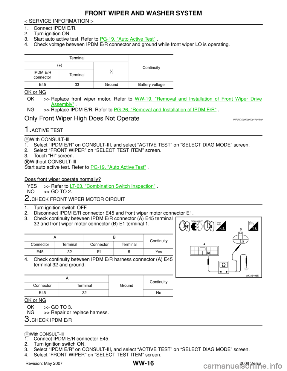
3. Check continuity between IPDM E/R connector (A) E45 terminal
32 and front wiper motor connector (B) E1 terminal 1.
4. Check continuity between IPDM E/R harness connector (A) E45
terminal 32 and ground.
OK or NG
OK >> GO TO 3.
NG >> Repair or replace harness.
3.CHECK IPDM E/R
With CONSULT-lIl
1. Connect IPDM E/R connector E45.
2. Turn ignition switch ON.
3. Select “IPDM E/R” on CONSULT-III, and select “ACTIVE TEST” on “SELECT DIAG MODE” screen.
4. Select “FRONT WIPER” on “SELECT TEST ITEM” screen.
Te r m i n a l
Continuity (+)
(-)
IPDM E/R
connectorTe r m i n a l
E45 33 Ground Battery voltage
AB
Continuity
Connector Terminal Connector Terminal
E45 32 E1 5 Yes
A
GroundContinuity
Connector Terminal
E45 32 No
WKIA5498E
Page 2750 of 2771
FRONT WIPER AND WASHER SYSTEM
WW-17
< SERVICE INFORMATION >
C
D
E
F
G
H
I
J
L
MA
B
WW
N
O
P
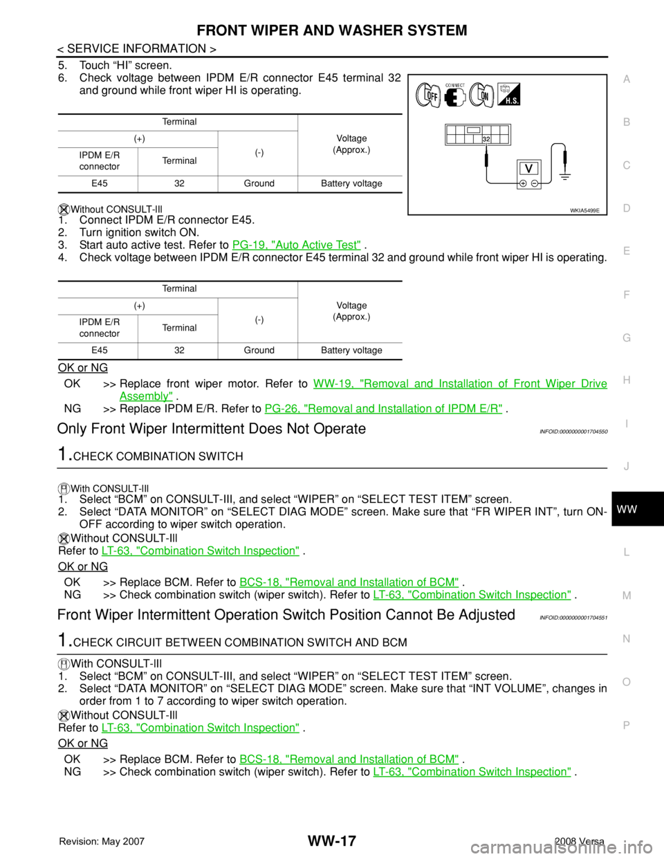
5. Touch “HI” screen.
6. Check voltage between IPDM E/R connector E45 terminal 32
and ground while front wiper HI is operating.
Without CONSULT-lIl
1. Connect IPDM E/R connector E45.
2. Turn ignition switch ON.
3. Start auto active test. Refer to PG-19, "
Auto Active Test" .
4. Check voltage between IPDM E/R connector E45 terminal 32 and ground while front wiper HI is operating.
OK or NG
OK >> Replace front wiper motor. Refer to WW-19, "Removal and Installation of Front Wiper Drive
Assembly" .
NG >> Replace IPDM E/R. Refer to PG-26, "
Removal and Installation of IPDM E/R" .
Only Front Wiper Intermittent Does Not OperateINFOID:0000000001704550
1.CHECK COMBINATION SWITCH
With CONSULT-lIl1. Select “BCM” on CONSULT-III, and select “WIPER” on “SELECT TEST ITEM” screen.
2. Select “DATA MONITOR” on “SELECT DIAG MODE” screen. Make sure that “FR WIPER INT”, turn ON-
OFF according to wiper switch operation.
Without CONSULT-Ill
Refer to LT-63, "
Combination Switch Inspection" .
OK or NG
OK >> Replace BCM. Refer to BCS-18, "Removal and Installation of BCM" .
NG >> Check combination switch (wiper switch). Refer to LT-63, "
Combination Switch Inspection" .
Front Wiper Intermittent Operation Switch Position Cannot Be AdjustedINFOID:0000000001704551
1.CHECK CIRCUIT BETWEEN COMBINATION SWITCH AND BCM
With CONSULT-lIl
1. Select “BCM” on CONSULT-III, and select “WIPER” on “SELECT TEST ITEM” screen.
2. Select “DATA MONITOR” on “SELECT DIAG MODE” screen. Make sure that “INT VOLUME”, changes in
order from 1 to 7 according to wiper switch operation.
Without CONSULT-Ill
Refer to LT-63, "
Combination Switch Inspection" .
OK or NG
OK >> Replace BCM. Refer to BCS-18, "Removal and Installation of BCM" .
NG >> Check combination switch (wiper switch). Refer to LT-63, "
Combination Switch Inspection" .
Te r m i n a l
Vo l ta g e
(Approx.) (+)
(-)
IPDM E/R
connectorTe r m i n a l
E45 32 Ground Battery voltage
Te r m i n a l
Vo l ta g e
(Approx.) (+)
(-)
IPDM E/R
connectorTe r m i n a l
E45 32 Ground Battery voltage
WKIA5499E
Page 2753 of 2771
WW-20
< SERVICE INFORMATION >
FRONT WIPER AND WASHER SYSTEM
2. Remove wiper arms. Refer to WW-18, "Removal and Installation of Front Wiper Arms" .
3. Remove cowl top cover. Refer to EI-21
.
4. Disconnect wiper motor connector.
5. Remove front wiper drive assembly bolts, and remove front wiper drive assembly.
INSTALLATION
1. Install front wiper drive assembly.
2. Connect wiper motor connector. Turn wiper switch on to operate wiper motor, then turn wiper switch off
(auto stop).
3. Install cowl top cover. Refer to EI-21
.
4. Install the wiper arms. Refer to WW-18, "
Removal and Installation of Front Wiper Arms" .
Removal and Installation of Front Washer NozzleINFOID:0000000001704557
REMOVAL
1. Remove cowl top cover. Refer to EI-21, "Removal and Installation" .
2. Remove washer tube.
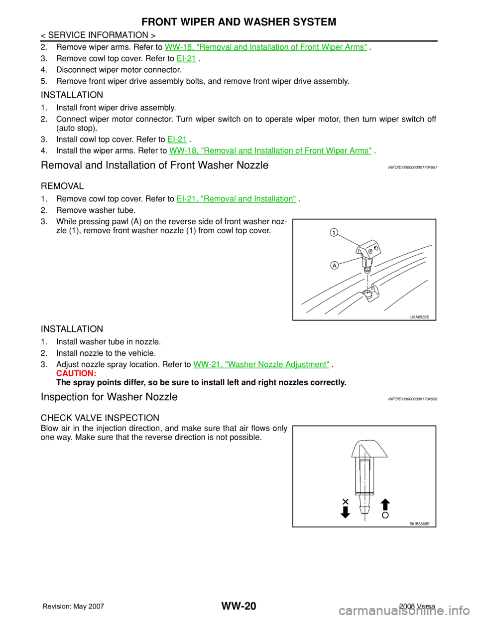
3. While pressing pawl (A) on the reverse side of front washer noz-
zle (1), remove front washer nozzle (1) from cowl top cover.
INSTALLATION
1. Install washer tube in nozzle.
2. Install nozzle to the vehicle.
3. Adjust nozzle spray location. Refer to WW-21, "
Washer Nozzle Adjustment" .
CAUTION:
The spray points differ, so be sure to install left and right nozzles correctly.
Inspection for Washer NozzleINFOID:0000000001704558
CHECK VALVE INSPECTION
Blow air in the injection direction, and make sure that air flows only
one way. Make sure that the reverse direction is not possible.
LKIA0939E
SKIB5665E
Page 2755 of 2771
WW-22
< SERVICE INFORMATION >
FRONT WIPER AND WASHER SYSTEM
Removal and Installation of Front Wiper and Washer Switch
INFOID:0000000001704561
REMOVAL
1. Remove the steering column cover. Refer to IP-10 .
2. Disconnect the wiper and washer switch connector.
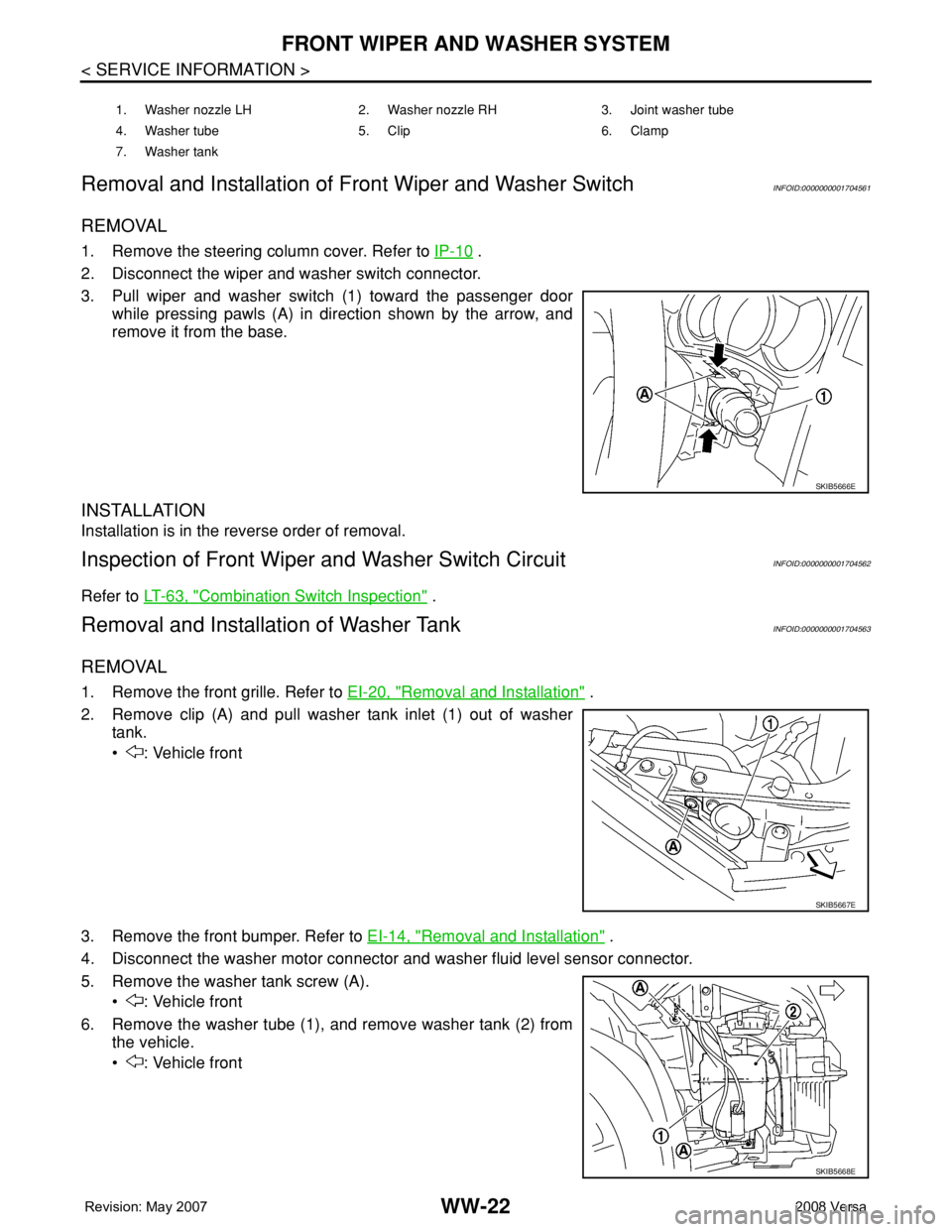
3. Pull wiper and washer switch (1) toward the passenger door
while pressing pawls (A) in direction shown by the arrow, and
remove it from the base.
INSTALLATION
Installation is in the reverse order of removal.
Inspection of Front Wiper and Washer Switch CircuitINFOID:0000000001704562
Refer to LT-63, "Combination Switch Inspection" .
Removal and Installation of Washer TankINFOID:0000000001704563
REMOVAL
1. Remove the front grille. Refer to EI-20, "Removal and Installation" .
2. Remove clip (A) and pull washer tank inlet (1) out of washer
tank.
• : Vehicle front
3. Remove the front bumper. Refer to EI-14, "
Removal and Installation" .
4. Disconnect the washer motor connector and washer fluid level sensor connector.
5. Remove the washer tank screw (A).
• : Vehicle front
6. Remove the washer tube (1), and remove washer tank (2) from
the vehicle.
• : Vehicle front
1. Washer nozzle LH 2. Washer nozzle RH 3. Joint washer tube
4. Washer tube 5. Clip 6. Clamp
7. Washer tank
SKIB5666E
SKIB5667E
SKIB5668E
Page 2756 of 2771
FRONT WIPER AND WASHER SYSTEM
WW-23
< SERVICE INFORMATION >
C
D
E
F
G
H
I
J
L
MA
B
WW
N
O
P
INSTALLATION
Installation is in the reverse order of removal.
CAUTION:
After installation, add water up to the upper level of washer tank inlet, and check for water leaks.
Removal and Installation of Front Washer MotorINFOID:0000000001704564
REMOVAL
1. Remove the front fender protector RH. Refer to EI-23 .
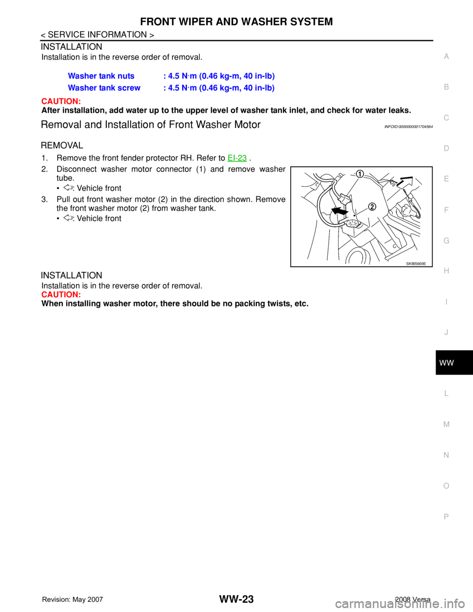
2. Disconnect washer motor connector (1) and remove washer
tube.
• : Vehicle front
3. Pull out front washer motor (2) in the direction shown. Remove
the front washer motor (2) from washer tank.
• : Vehicle front
INSTALLATION
Installation is in the reverse order of removal.
CAUTION:
When installing washer motor, there should be no packing twists, etc. Washer tank nuts : 4.5 N·m (0.46 kg-m, 40 in-lb)
Washer tank screw : 4.5 N·m (0.46 kg-m, 40 in-lb)
SKIB5669E