2008 NISSAN TIIDA Index
[x] Cancel search: IndexPage 1 of 2771

-1
QUICK REFERENCE INDEX
AGENERAL INFORMATIONGIGeneral Information
BENGINEEMEngine Mechanical
LUEngine Lubrication System
COEngine Cooling System
ECEngine Control System
FLFuel System
EXExhaust System
ACCAccelerator Control System
CTRANSMISSION/
TRANSAXLECLClutch System
MTManual Transaxle
ATAutomatic Transaxle
CVTCVT
DDRIVELINE/AXLEFAXFront Axle
RAXRear Axle
ESUSPENSIONFSUFront Suspension
RSURear Suspension
WTRoad Wheels & Tires
FBRAKESBRBrake System
PBParking Brake System
BRCBrake Control System
GSTEERINGPSPower Steering System
STCSteering Control System
HRESTRAINTSSBSeat Belts
SRSSupplemental Restraint System (SRS)
IBODYBLBody, Lock & Security System
GWGlasses, Window System & Mirrors
RFRoof
EIExterior & Interior
IPInstrument Panel
SESeat
JAIR CONDITIONERMTCManual Air Conditioner
KELECTRICALSCStarting & Charging System
LTLighting System
DIDriver Information System
WWWiper, Washer & Horn
BCSBody Control System
LANLAN System
AVAudio Visual, Navigation & Telephone System
ACSAuto Cruise Control System
PGPower Supply, Ground & Circuit Elements
LMAINTENANCEMAMaintenance
Edition: May 2007
Revision: May 2007
Publication No. SM8E-1C11U0
B
D
© 2007 NISSAN NORTH AMERICA, INC.
All rights reserved. No part of this Service Manual may be reproduced or stored in a retrieval system, or transmitted in any
form, or by any means, electronic, mechanical, photo-copying, recording or otherwise, without the prior written permission
of Nissan North America Inc.
A
C
E
F
G
H
I
J
K
L
M
Page 3 of 2771
PLEASEHELPMAKETHISSERVICEMANUALBETTER!
YourcommentsareimportanttoNISSANandwillhelpustoimproveourServiceManuals.
UsethisformtoreportanyissuesorcommentsyoumayhaveregardingourServiceManuals.
Pleaseprintthisformandtypeorwriteyourcommentsbelow.Mailorfaxto:
NissanNorthAmerica,Inc.
TechnicalServiceInformation
39001SunriseDrive,P.O.Box9200
FarmingtonHills,MIUSA48331
FAX:(248)488-3910
SERVICEMANUAL:Model:Year:
PUBLICATIONNO.(Refer to Quick Reference Index ):
Pleasedescribeany Service Manualissuesorproblemsindetail:
Pagenumber(s)Note:Pleaseincludeacopyofeachpage,markedwithyourcomments.
Arethetroublediagnosisprocedureslogicalandeasytouse?(circleyouranswer)YESNO
Ifno,whatpagenumber(s)?Note:Pleaseincludeacopyofeachpage,markedwithyourcomments.
Pleasedescribetheissueorproblemindetail:
Istheorganizationofthemanualclearandeasytofollow?(circleyouranswer)YESNO
Pleasecomment:
WhatinformationshouldbeincludedinNISSANServiceManualstobettersupportyouinservicingor
repairingcustomervehicles?
DATE:YOURNAME:POSITION:
DEALER:DEALERNO.:ADDRESS:
CITY:STATE/PROV./COUNTRY:ZIP/POSTALCODE:
Page 13 of 2771

AT-1
TRANSMISSION/TRANSAXLE
D
E
F
G
H
I
J
K
L
M
SECTION AT
A
B
AT
N
O
P
CONTENTS
AUTOMATIC TRANSAXLE
SERVICE INFORMATION ............................5
INDEX FOR DTC .................................................5
Alphabetical Index .....................................................5
DTC No. Index ..........................................................5
PRECAUTIONS ...................................................7
Precaution for Supplemental Restraint System
(SRS) "AIR BAG" and "SEAT BELT PRE-TEN-
SIONER" ...................................................................
7
Precaution Necessary for Steering Wheel Rota-
tion After Battery Disconnect .....................................
7
Precaution for On Board Diagnosis (OBD) System
of A/T and Engine .....................................................
7
Precaution .................................................................8
Service Notice or Precaution .....................................9
PREPARATION ..................................................10
Special Service Tool ...............................................10
Commercial Service Tool ........................................13
A/T FLUID ...........................................................15
Checking A/T Fluid ..................................................15
Changing A/T Fluid .................................................15
A/T Fluid Cooler Cleaning .......................................16
A/T CONTROL SYSTEM ....................................19
Cross-Sectional View ..............................................19
Shift Mechanism ......................................................19
TCM Function ..........................................................27
CAN Communication ...............................................28
Input/Output Signal of TCM .....................................28
Line Pressure Control .............................................29
Shift Control ............................................................30
Lock-up Control .......................................................31
Engine Brake Control (Overrun Clutch Control) ......32
Control Valve ...........................................................34
Centrifugal Cancel Mechanism ...............................34
ON BOARD DIAGNOSTIC (OBD) SYSTEM ......36
Introduction .............................................................36
OBD-II Function for A/T System ..............................36
One or Two Trip Detection Logic of OBD-II .............36
OBD-II Diagnostic Trouble Code (DTC) ..................36
Malfunction Indicator Lamp (MIL) ............................38
TROUBLE DIAGNOSIS ....................................39
DTC Inspection Priority Chart ..................................39
Fail-Safe ..................................................................39
How to Perform Trouble Diagnosis for Quick and
Accurate Repair .......................................................
40
A/T Electrical Parts Location ...................................46
Circuit Diagram ........................................................47
Inspections Before Trouble Diagnosis .....................48
Road Test ................................................................52
Check Before Engine Is Started ..............................53
Check at Idle ............................................................53
Cruise Test - Part 1 .................................................55
Cruise Test - Part 2 .................................................58
Cruise Test - Part 3 .................................................59
Vehicle Speed at Which Gear Shifting Occurs ........61
Vehicle Speed at Which Lock-up Occurs/Releas-
es .............................................................................
61
Symptom Chart ........................................................61
TCM Terminal and Reference Value .......................71
CONSULT-III Function (A/T) ...................................73
Diagnosis Procedure without CONSULT-III ............78
DTC U1000 CAN COMMUNICATION LINE .....83
Description ...............................................................83
On Board Diagnosis Logic .......................................83
Possible Cause ........................................................83
DTC Confirmation Procedure ..................................83
Wiring Diagram - AT - CAN .....................................84
Diagnosis Procedure ...............................................85
DTC P0705 PARK/NEUTRAL POSITION
(PNP) SWITCH ..................................................
86
Description ...............................................................86
CONSULT-III Reference Value in Data Monitor
Mode ........................................................................
86
On Board Diagnosis Logic .......................................86
Possible Cause ........................................................86
Page 17 of 2771
INDEX FOR DTC
AT-5
< SERVICE INFORMATION >
D
E
F
G
H
I
J
K
L
MA
B
AT
N
O
P
SERVICE INFORMATION
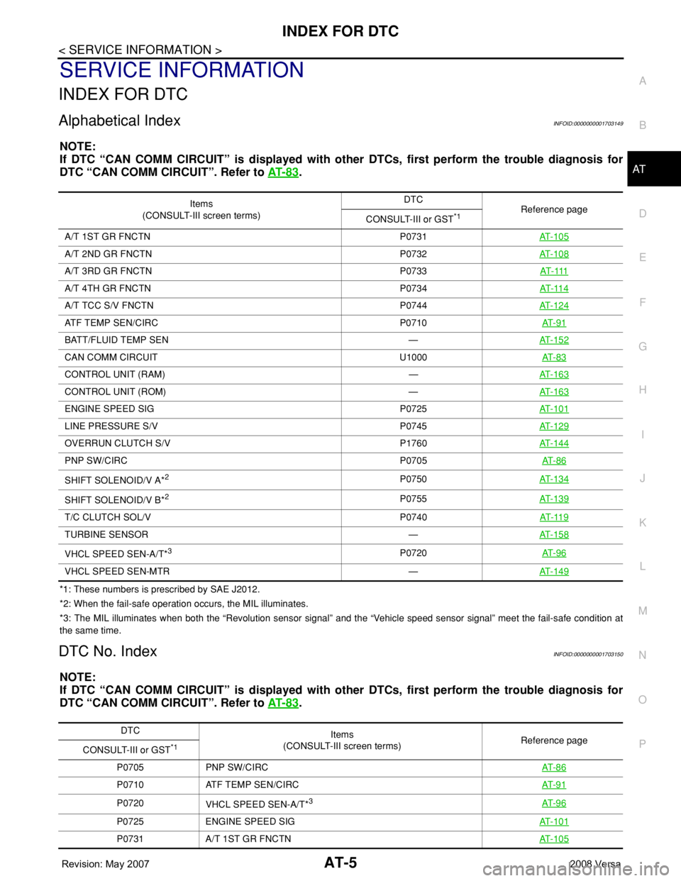
INDEX FOR DTC
Alphabetical IndexINFOID:0000000001703149
NOTE:
If DTC “CAN COMM CIRCUIT” is displayed with other DTCs, first perform the trouble diagnosis for
DTC “CAN COMM CIRCUIT”. Refer to AT- 8 3
.
*1: These numbers is prescribed by SAE J2012.
*2: When the fail-safe operation occurs, the MIL illuminates.
*3: The MIL illuminates when both the “Revolution sensor signal” and the “Vehicle speed sensor signal” meet the fail-safe condition at
the same time.
DTC No. IndexINFOID:0000000001703150
NOTE:
If DTC “CAN COMM CIRCUIT” is displayed with other DTCs, first perform the trouble diagnosis for
DTC “CAN COMM CIRCUIT”. Refer to AT- 8 3
.
Items
(CONSULT-III screen terms)DTC
Reference page
CONSULT-III or GST
*1
A/T 1ST GR FNCTN P0731AT-105
A/T 2ND GR FNCTN P0732AT-108
A/T 3RD GR FNCTN P0733AT- 111
A/T 4TH GR FNCTN P0734AT- 11 4
A/T TCC S/V FNCTN P0744AT-124
ATF TEMP SEN/CIRC P0710AT- 9 1
BATT/FLUID TEMP SEN —AT-152
CAN COMM CIRCUIT U1000AT- 8 3
CONTROL UNIT (RAM) —AT-163
CONTROL UNIT (ROM) —AT-163
ENGINE SPEED SIG P0725AT-101
LINE PRESSURE S/V P0745AT-129
OVERRUN CLUTCH S/V P1760AT-144
PNP SW/CIRC P0705AT- 8 6
SHIFT SOLENOID/V A*2P0750AT-134
SHIFT SOLENOID/V B*2P0755AT-139
T/C CLUTCH SOL/V P0740AT- 11 9
TURBINE SENSOR —AT-158
VHCL SPEED SEN-A/T*3P0720AT- 9 6
VHCL SPEED SEN-MTR —AT-149
DTC
Items
(CONSULT-III screen terms) Reference page
CONSULT-III or GST
*1
P0705 PNP SW/CIRCAT- 8 6
P0710 ATF TEMP SEN/CIRCAT- 9 1
P0720
VHCL SPEED SEN-A/T*3AT- 9 6
P0725 ENGINE SPEED SIGAT- 1 0 1
P0731 A/T 1ST GR FNCTNAT- 1 0 5
Page 18 of 2771
AT-6
< SERVICE INFORMATION >
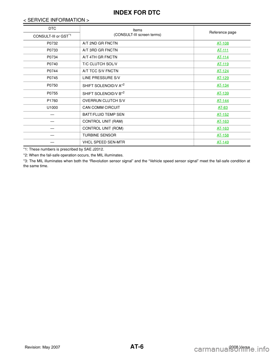
INDEX FOR DTC
*1: These numbers is prescribed by SAE J2012.
*2: When the fail-safe operation occurs, the MIL illuminates.
*3: The MIL illuminates when both the “Revolution sensor signal” and the “Vehicle speed sensor signal” meet the fail-safe condition at
the same time.P0732 A/T 2ND GR FNCTNAT- 1 0 8
P0733 A/T 3RD GR FNCTNAT- 111
P0734 A/T 4TH GR FNCTNAT- 11 4
P0740 T/C CLUTCH SOL/VAT- 11 9
P0744 A/T TCC S/V FNCTNAT- 1 2 4
P0745 LINE PRESSURE S/VAT- 1 2 9
P0750
SHIFT SOLENOID/V A*2AT- 1 3 4
P0755
SHIFT SOLENOID/V B*2AT- 1 3 9
P1760 OVERRUN CLUTCH S/VAT- 1 4 4
U1000 CAN COMM CIRCUITAT- 8 3
— BATT/FLUID TEMP SENAT- 1 5 2
— CONTROL UNIT (RAM)AT- 1 6 3
— CONTROL UNIT (ROM)AT- 1 6 3
— TURBINE SENSORAT- 1 5 8
— VHCL SPEED SEN-MTRAT- 1 4 9
DTC
Items
(CONSULT-III screen terms) Reference page
CONSULT-III or GST
*1
Page 840 of 2771
CVT-1
TRANSMISSION/TRANSAXLE
D
E
F
G
H
I
J
K
L
M
SECTION CVT
A
B
CVT
N
O
P
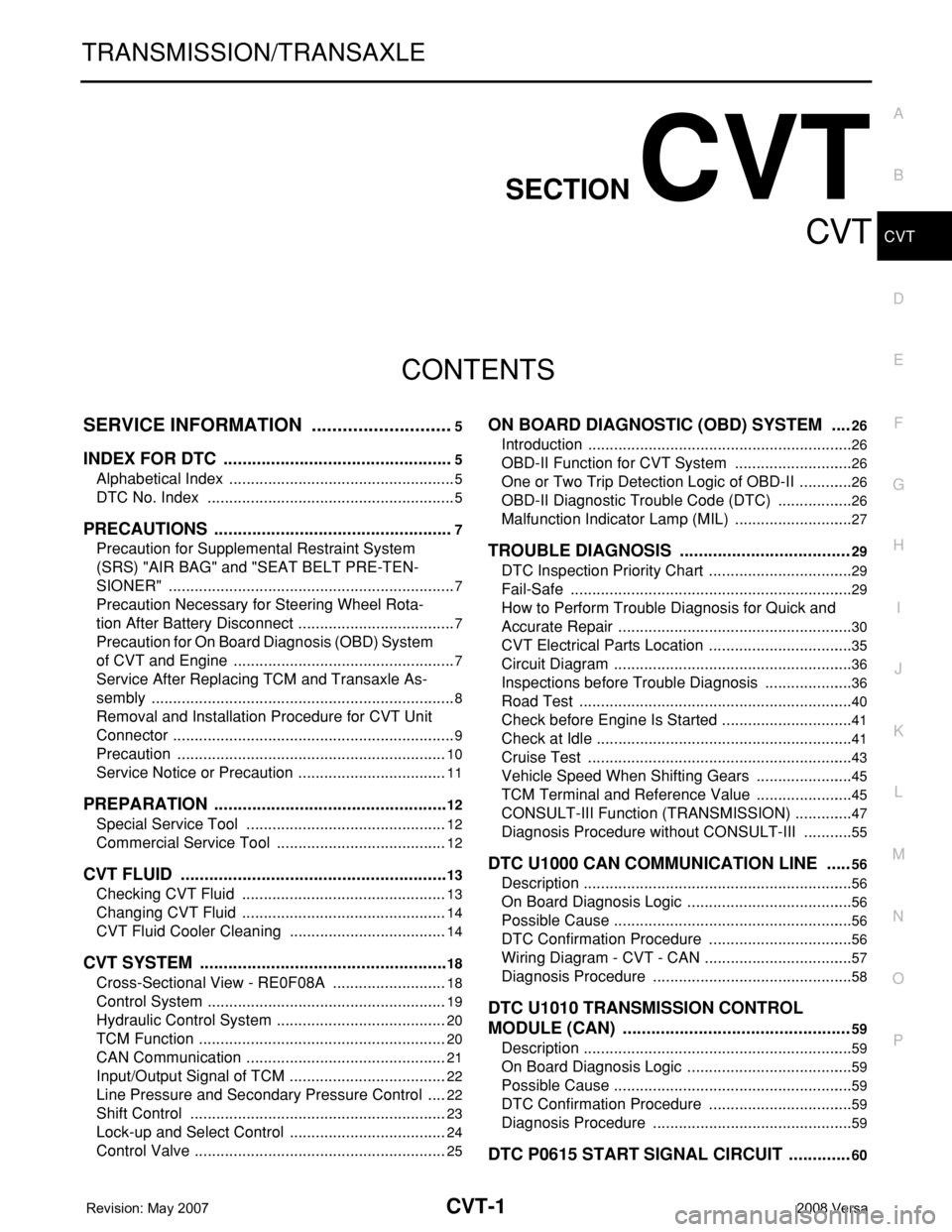
CONTENTS
CVT
SERVICE INFORMATION ............................5
INDEX FOR DTC .................................................5
Alphabetical Index .....................................................5
DTC No. Index ..........................................................5
PRECAUTIONS ...................................................7
Precaution for Supplemental Restraint System
(SRS) "AIR BAG" and "SEAT BELT PRE-TEN-
SIONER" ...................................................................
7
Precaution Necessary for Steering Wheel Rota-
tion After Battery Disconnect .....................................
7
Precaution for On Board Diagnosis (OBD) System
of CVT and Engine ....................................................
7
Service After Replacing TCM and Transaxle As-
sembly .......................................................................
8
Removal and Installation Procedure for CVT Unit
Connector ..................................................................
9
Precaution ...............................................................10
Service Notice or Precaution ...................................11
PREPARATION ..................................................12
Special Service Tool ...............................................12
Commercial Service Tool ........................................12
CVT FLUID .........................................................13
Checking CVT Fluid ................................................13
Changing CVT Fluid ................................................14
CVT Fluid Cooler Cleaning .....................................14
CVT SYSTEM .....................................................18
Cross-Sectional View - RE0F08A ...........................18
Control System ........................................................19
Hydraulic Control System ........................................20
TCM Function ..........................................................20
CAN Communication ...............................................21
Input/Output Signal of TCM .....................................22
Line Pressure and Secondary Pressure Control .....22
Shift Control ............................................................23
Lock-up and Select Control .....................................24
Control Valve ...........................................................25
ON BOARD DIAGNOSTIC (OBD) SYSTEM ....26
Introduction ..............................................................26
OBD-II Function for CVT System ............................26
One or Two Trip Detection Logic of OBD-II .............26
OBD-II Diagnostic Trouble Code (DTC) ..................26
Malfunction Indicator Lamp (MIL) ............................27
TROUBLE DIAGNOSIS ....................................29
DTC Inspection Priority Chart ..................................29
Fail-Safe ..................................................................29
How to Perform Trouble Diagnosis for Quick and
Accurate Repair .......................................................
30
CVT Electrical Parts Location ..................................35
Circuit Diagram ........................................................36
Inspections before Trouble Diagnosis .....................36
Road Test ................................................................40
Check before Engine Is Started ...............................41
Check at Idle ............................................................41
Cruise Test ..............................................................43
Vehicle Speed When Shifting Gears .......................45
TCM Terminal and Reference Value .......................45
CONSULT-III Function (TRANSMISSION) ..............47
Diagnosis Procedure without CONSULT-III ............55
DTC U1000 CAN COMMUNICATION LINE .....56
Description ...............................................................56
On Board Diagnosis Logic .......................................56
Possible Cause ........................................................56
DTC Confirmation Procedure ..................................56
Wiring Diagram - CVT - CAN ...................................57
Diagnosis Procedure ...............................................58
DTC U1010 TRANSMISSION CONTROL
MODULE (CAN) ................................................
59
Description ...............................................................59
On Board Diagnosis Logic .......................................59
Possible Cause ........................................................59
DTC Confirmation Procedure ..................................59
Diagnosis Procedure ...............................................59
DTC P0615 START SIGNAL CIRCUIT .............60
Page 844 of 2771
INDEX FOR DTC
CVT-5
< SERVICE INFORMATION >
D
E
F
G
H
I
J
K
L
MA
B
CVT
N
O
P
SERVICE INFORMATION
INDEX FOR DTC
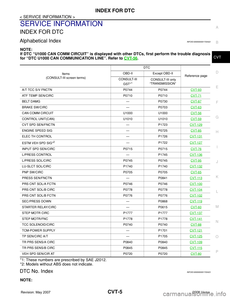
Alphabetical IndexINFOID:0000000001703422
NOTE:
If DTC “U1000 CAN COMM CIRCUIT” is displayed with other DTCs, first perform the trouble diagnosis
for “DTC U1000 CAN COMMUNICATION LINE”. Refer to CVT-56
.
*1: These numbers are prescribed by SAE J2012.
*2: Models without ABS does not indicate.
DTC No. IndexINFOID:0000000001703423
NOTE:
Items
(CONSULT-III screen terms) DTC
Reference page OBD-II Except OBD-II
CONSULT-III
GST*
1 CONSULT-III only
“TRANSMISSION”
A/T TCC S/V FNCTN P0744 P0744 CVT-93
ATF TEMP SEN/CIRC P0710 P0710CVT-71
BELT DAMG — P0730CVT-87
BRAKE SW/CIRC — P0703CVT-63
CAN COMM CIRCUIT U1000 U1000CVT-56
CONTROL UNIT(CAN) U1010 U1010CVT-59
CVT SPD SEN/FNCTN — P1723CVT-129
ENGINE SPEED SIG — P0725CVT-85
ELEC TH CONTROL — P1726CVT-131
ESTM VEH SPD SIG*2— P1722CVT-127
INPUT SPD SEN/CIRC P0715 P0715CVT-76
L/PRESS CONTROL — P1745CVT-136
L/PRESS SOL/CIRC P0745 P0745CVT-95
LU-SLCT SOL/CIRC P1740 P1740CVT-132
PNP SW/CIRC P0705 P0705CVT-65
PRESS SEN/FNCTN — P0841CVT-113
PRS CNT SOL/A FCTN P0746 P0746CVT-100
PRS CNT SOL/B CIRC P0778 P0778CVT-104
PRS CNT SOL/B FCTN P0776 P0776CVT-102
SEC/PRESS DOWN — P0868CVT-119
STARTER RELAY/CIRC — P0615CVT-60
STEP MOTR CIRC P1777 P1777CVT-137
STEP MOTR/FNC P1778 P1778CVT-141
TCC SOLENOID/CIRC P0740 P0740CVT-88
TCM-POWER SUPPLY — P1701CVT-121
TP SEN/CIRC A/T — P1705CVT-125
TR PRS SENS/A CIRC P0840 P0840CVT-109
TR PRS SENS/B CIRC P0845 P0845CVT-115
VEH SPD SEN/CIR AT P0720 P0720CVT-80
Page 845 of 2771
CVT-6
< SERVICE INFORMATION >
INDEX FOR DTC
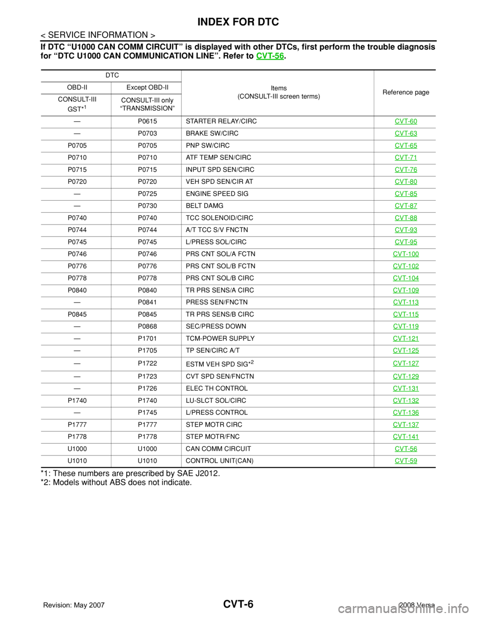
If DTC “U1000 CAN COMM CIRCUIT” is displayed with other DTCs, first perform the trouble diagnosis
for “DTC U1000 CAN COMMUNICATION LINE”. Refer to CVT-56
.
*1: These numbers are prescribed by SAE J2012.
*2: Models without ABS does not indicate.
DTC
Items
(CONSULT-III screen terms)Reference page OBD-II Except OBD-II
CONSULT-III
GST*
1CONSULT-III only
“TRANSMISSION”
— P0615 STARTER RELAY/CIRCCVT-60
— P0703 BRAKE SW/CIRCCVT-63
P0705 P0705 PNP SW/CIRCCVT-65
P0710 P0710 ATF TEMP SEN/CIRCCVT-71
P0715 P0715 INPUT SPD SEN/CIRCCVT-76
P0720 P0720 VEH SPD SEN/CIR ATCVT-80
— P0725 ENGINE SPEED SIGCVT-85
— P0730 BELT DAMGCVT-87
P0740 P0740 TCC SOLENOID/CIRCCVT-88
P0744 P0744 A/T TCC S/V FNCTNCVT-93
P0745 P0745 L/PRESS SOL/CIRCCVT-95
P0746 P0746 PRS CNT SOL/A FCTNCVT-100
P0776 P0776 PRS CNT SOL/B FCTNCVT-102
P0778 P0778 PRS CNT SOL/B CIRCCVT-104
P0840 P0840 TR PRS SENS/A CIRCCVT-109
— P0841 PRESS SEN/FNCTNCVT-113
P0845 P0845 TR PRS SENS/B CIRCCVT-115
— P0868 SEC/PRESS DOWNCVT-119
— P1701 TCM-POWER SUPPLYCVT-121
— P1705 TP SEN/CIRC A/TCVT-125
— P1722
ESTM VEH SPD SIG*2CVT-127
— P1723 CVT SPD SEN/FNCTNCVT-129
— P1726 ELEC TH CONTROLCVT-131
P1740 P1740 LU-SLCT SOL/CIRCCVT-132
— P1745 L/PRESS CONTROLCVT-136
P1777 P1777 STEP MOTR CIRCCVT-137
P1778 P1778 STEP MOTR/FNCCVT-141
U1000 U1000 CAN COMM CIRCUITCVT-56
U1010 U1010 CONTROL UNIT(CAN)CVT-59