2008 NISSAN TEANA Control Valve Assembly
[x] Cancel search: Control Valve AssemblyPage 906 of 5121

BR-10
< ON-VEHICLE MAINTENANCE >
BRAKE FLUID
2. Loosen the bleeder valve, slowly depress the brake pedal to the full stroke, and then release the pedal.
Repeat this operation at intervals of 2 or 3 seconds until all brake fluid is discharged. Then close the
bleeder valve with the brake pedal depressed. Repeat the same work on each wheel.
3. Perform the air bleeding. Refer to BR-10, "
Bleeding Brake System".
Bleeding Brake SystemINFOID:0000000003811176
CAUTION:
Turn the ignition switch OFF and disconnect the ABS actuator and electric unit (control unit) con-
nector or the battery negative terminal before performing the work.
Monitor the fluid level in the sub tank during the air bleeding.
Always use new brake fluid for refilling. Never reuse the drained brake fluid.
1. Connect a vinyl tube to the bleeder valve of the rear right brake.
2. Fully depress the brake pedal 4 to 5 times.
3. Loosen the bleeder valve and bleed air with the brake pedal depressed, and then quickly tighten the
bleeder valve.
4. Repeat steps 2 and 3 until all of the air is out of the brake line.
5. Tighten the bleeder valve to the specified torque.
Front disc brake: refer to BR-34, "
BRAKE CALIPER ASSEMBLY : Exploded View".
Rear disc brake: refer to BR-40, "
BRAKE CALIPER ASSEMBLY : Exploded View".
6. Perform steps 1 to 5 for the rear right brake → front left brake → rear left brake → and front right brake in
order.
7. Check that the fluid level in the sub tank is within the specified range after air bleeding. Refer to BR-9,
"Inspection".
Page 1011 of 5121
![NISSAN TEANA 2008 Service Manual BRC-70
< FUNCTION DIAGNOSIS >[VDC/TCS/ABS]
VDC
Component Description
INFOID:0000000003766888
A. Back of spiral cable assembly B. Combination meter C. Under center console
D. Engine room right side E.](/manual-img/5/57391/w960_57391-1010.png "NISSAN TEANA 2008 Service Manual BRC-70
< FUNCTION DIAGNOSIS >[VDC/TCS/ABS]
VDC
Component Description
INFOID:0000000003766888
A. Back of spiral cable assembly B. Combination meter C. Under center console
D. Engine room right side E.")
BRC-70
< FUNCTION DIAGNOSIS >[VDC/TCS/ABS]
VDC
Component Description
INFOID:0000000003766888
A. Back of spiral cable assembly B. Combination meter C. Under center console
D. Engine room right side E. Steering knuckle F. Instrument driver lower panel
G. Rear axle
Component parts Reference
ABS actuator and electric unit (control unit)Pump
BRC-94, "
Description"Motor
Actuator relay (main relay)BRC-106, "
Description"
Solenoid valveBRC-101, "Description"
Pressure sensorBRC-108, "Description"
VDC switch-over valve (USV1, USV2)BRC-118, "Description"
VDC switch-over valve (HSV1, HSV2)BRC-120, "Description"
Wheel sensorBRC-85, "Description"
Yaw rate/side G sensorBRC-113, "Description"
Steering angle sensorBRC-110, "Description"
VDC OFF switchBRC-126, "Description"
ABS warning lampBRC-128, "Description"
Brake warning lampBRC-129, "Description"
VDC OFF indicator lampBRC-130, "Description"
SLIP indicator lampBRC-131, "Description"
Page 1014 of 5121
![NISSAN TEANA 2008 Service Manual TCS
BRC-73
< FUNCTION DIAGNOSIS >[VDC/TCS/ABS]
C
D
E
G
H
I
J
K
L
MA
B
BRC
N
O
P
Component DescriptionINFOID:0000000003767314
A. Back of spiral cable assembly B. Combination meter C. Under center conso](/manual-img/5/57391/w960_57391-1013.png "NISSAN TEANA 2008 Service Manual TCS
BRC-73
< FUNCTION DIAGNOSIS >[VDC/TCS/ABS]
C
D
E
G
H
I
J
K
L
MA
B
BRC
N
O
P
Component DescriptionINFOID:0000000003767314
A. Back of spiral cable assembly B. Combination meter C. Under center conso")
TCS
BRC-73
< FUNCTION DIAGNOSIS >[VDC/TCS/ABS]
C
D
E
G
H
I
J
K
L
MA
B
BRC
N
O
P
Component DescriptionINFOID:0000000003767314
A. Back of spiral cable assembly B. Combination meter C. Under center console
D. Engine room right side E. Steering knuckle F. Instrument driver lower panel
G. Rear axle
Component parts Reference
ABS actuator and electric unit (control unit)Pump
BRC-94, "
Description"Motor
Actuator relay (main relay)BRC-106, "
Description"
Solenoid valveBRC-103, "Description"
Pressure sensorBRC-108, "Description"
VDC switch-over valve (USV1, USV2)BRC-118, "Description"
VDC switch-over valve (HSV1, HSV2)BRC-120, "Description"
Wheel sensorBRC-96, "Description"
Yaw rate/side G sensorBRC-113, "Description"
Steering angle sensorBRC-110, "Description"
VDC OFF switchBRC-126, "Description"
ABS warning lampBRC-128, "Description"
Brake warning lampBRC-129, "Description"
VDC OFF indicator lampBRC-130, "Description"
SLIP indicator lampBRC-131, "Description"
Page 1017 of 5121
![NISSAN TEANA 2008 Service Manual BRC-76
< FUNCTION DIAGNOSIS >[VDC/TCS/ABS]
ABS
Component Description
INFOID:0000000003767317
A. Back of spiral cable assembly B. Combination meter C. Under center console
D. Engine room right side E.](/manual-img/5/57391/w960_57391-1016.png "NISSAN TEANA 2008 Service Manual BRC-76
< FUNCTION DIAGNOSIS >[VDC/TCS/ABS]
ABS
Component Description
INFOID:0000000003767317
A. Back of spiral cable assembly B. Combination meter C. Under center console
D. Engine room right side E.")
BRC-76
< FUNCTION DIAGNOSIS >[VDC/TCS/ABS]
ABS
Component Description
INFOID:0000000003767317
A. Back of spiral cable assembly B. Combination meter C. Under center console
D. Engine room right side E. Steering knuckle F. Instrument driver lower panel
G. Rear axle
Component parts Reference
ABS actuator and electric unit (control unit)Pump
BRC-94, "
Description"Motor
Actuator relay (main relay)BRC-106, "
Description"
Solenoid valveBRC-103, "Description"
Pressure sensorBRC-108, "Description"
VDC switch-over valve (USV1, USV2)BRC-118, "Description"
VDC switch-over valve (HSV1, HSV2)BRC-120, "Description"
Wheel sensorBRC-96, "Description"
Yaw rate/side G sensorBRC-113, "Description"
Steering angle sensorBRC-110, "Description"
VDC OFF switchBRC-126, "Description"
ABS warning lampBRC-128, "Description"
Brake warning lampBRC-129, "Description"
VDC OFF indicator lampBRC-130, "Description"
SLIP indicator lampBRC-131, "Description"
Page 1020 of 5121
![NISSAN TEANA 2008 Service Manual EBD
BRC-79
< FUNCTION DIAGNOSIS >[VDC/TCS/ABS]
C
D
E
G
H
I
J
K
L
MA
B
BRC
N
O
P
Component DescriptionINFOID:0000000003767320
A. Back of spiral cable assembly B. Combination meter C. Under center conso](/manual-img/5/57391/w960_57391-1019.png "NISSAN TEANA 2008 Service Manual EBD
BRC-79
< FUNCTION DIAGNOSIS >[VDC/TCS/ABS]
C
D
E
G
H
I
J
K
L
MA
B
BRC
N
O
P
Component DescriptionINFOID:0000000003767320
A. Back of spiral cable assembly B. Combination meter C. Under center conso")
EBD
BRC-79
< FUNCTION DIAGNOSIS >[VDC/TCS/ABS]
C
D
E
G
H
I
J
K
L
MA
B
BRC
N
O
P
Component DescriptionINFOID:0000000003767320
A. Back of spiral cable assembly B. Combination meter C. Under center console
D. Engine room right side E. Steering knuckle F. Instrument driver lower panel
G. Rear axle
Component parts Reference
ABS actuator and electric unit (control unit)Pump
BRC-94, "
Description"Motor
Actuator relay (main relay)BRC-106, "
Description"
Solenoid valveBRC-103, "Description"
Pressure sensorBRC-108, "Description"
VDC switch-over valve (USV1, USV2)BRC-118, "Description"
VDC switch-over valve (HSV1, HSV2)BRC-120, "Description"
Wheel sensorBRC-96, "Description"
Yaw rate/side G sensorBRC-113, "Description"
Steering angle sensorBRC-110, "Description"
VDC OFF switchBRC-126, "Description"
ABS warning lampBRC-128, "Description"
Brake warning lampBRC-129, "Description"
VDC OFF indicator lampBRC-130, "Description"
SLIP indicator lampBRC-131, "Description"
Page 1141 of 5121
CO-18
< ON-VEHICLE REPAIR >
WATER PUMP
WATER PUMP
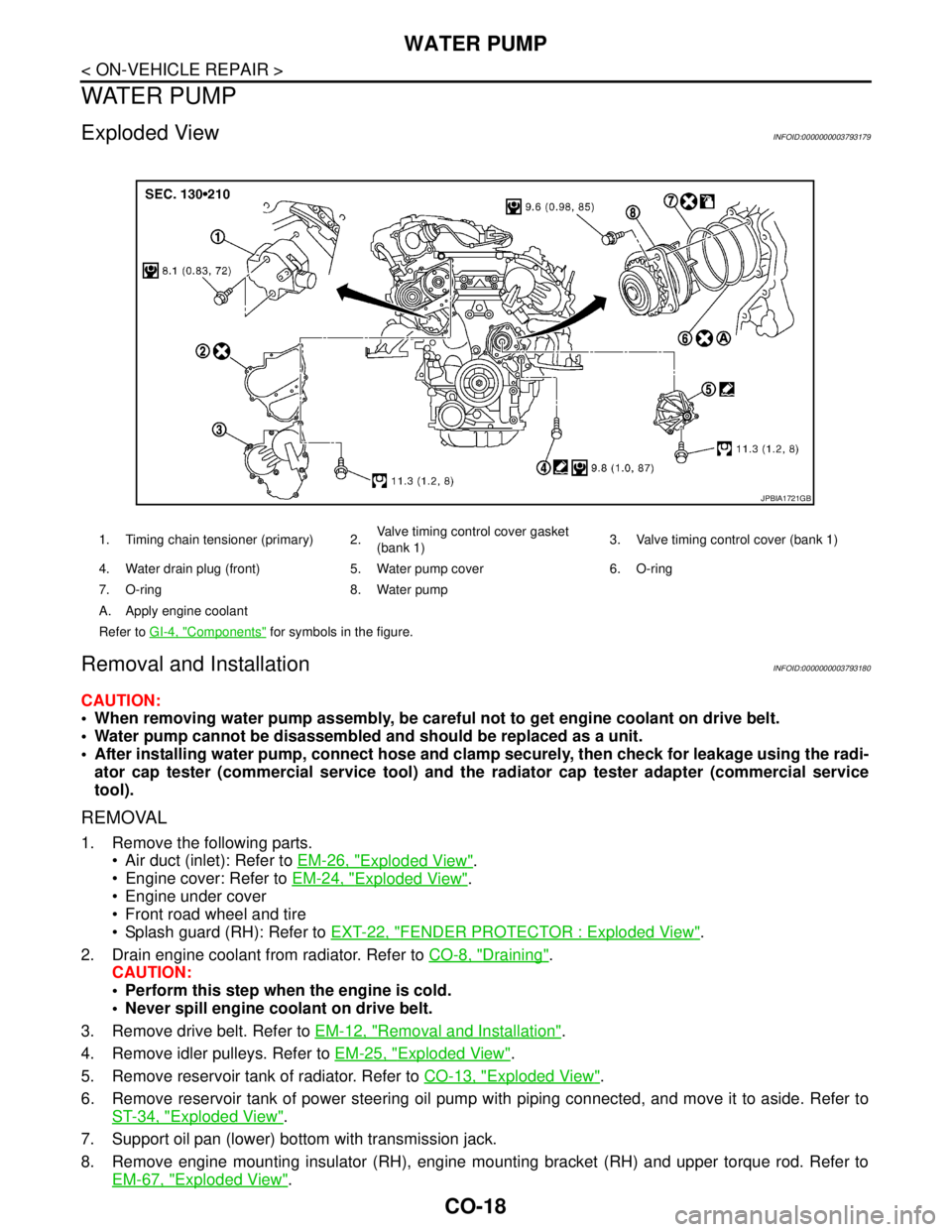
Exploded ViewINFOID:0000000003793179
Removal and InstallationINFOID:0000000003793180
CAUTION:
When removing water pump assembly, be careful not to get engine coolant on drive belt.
Water pump cannot be disassembled and should be replaced as a unit.
After installing water pump, connect hose and clamp securely, then check for leakage using the radi-
ator cap tester (commercial service tool) and the radiator cap tester adapter (commercial service
tool).
REMOVAL
1. Remove the following parts.
Air duct (inlet): Refer to EM-26, "
Exploded View".
Engine cover: Refer to EM-24, "
Exploded View".
Engine under cover
Front road wheel and tire
Splash guard (RH): Refer to EXT-22, "
FENDER PROTECTOR : Exploded View".
2. Drain engine coolant from radiator. Refer to CO-8, "
Draining".
CAUTION:
Perform this step when the engine is cold.
Never spill engine coolant on drive belt.
3. Remove drive belt. Refer to EM-12, "
Removal and Installation".
4. Remove idler pulleys. Refer to EM-25, "
Exploded View".
5. Remove reservoir tank of radiator. Refer to CO-13, "
Exploded View".
6. Remove reservoir tank of power steering oil pump with piping connected, and move it to aside. Refer to
ST-34, "
Exploded View".
7. Support oil pan (lower) bottom with transmission jack.
8. Remove engine mounting insulator (RH), engine mounting bracket (RH) and upper torque rod. Refer to
EM-67, "
Exploded View".
1. Timing chain tensioner (primary) 2.Valve timing control cover gasket
(bank 1)3. Valve timing control cover (bank 1)
4. Water drain plug (front) 5. Water pump cover 6. O-ring
7. O-ring 8. Water pump
A. Apply engine coolant
Refer to GI-4, "
Components" for symbols in the figure.
JPBIA1721GB
Page 1144 of 5121
WATER PUMP
CO-21
< ON-VEHICLE REPAIR >
C
D
E
F
G
H
I
J
K
L
MA
CO
N
P O
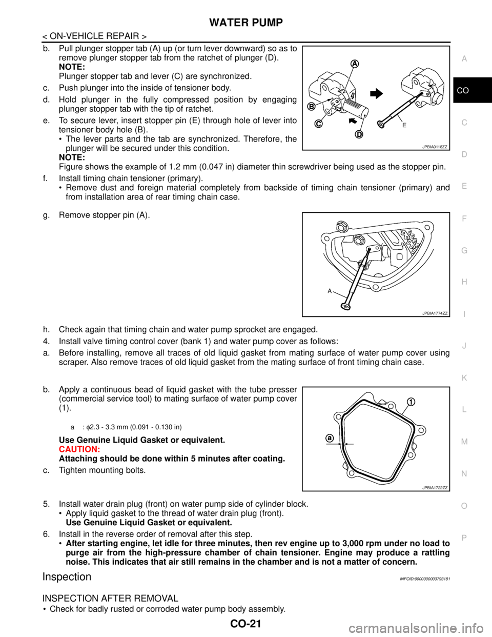
b. Pull plunger stopper tab (A) up (or turn lever downward) so as to
remove plunger stopper tab from the ratchet of plunger (D).
NOTE:
Plunger stopper tab and lever (C) are synchronized.
c. Push plunger into the inside of tensioner body.
d. Hold plunger in the fully compressed position by engaging
plunger stopper tab with the tip of ratchet.
e. To secure lever, insert stopper pin (E) through hole of lever into
tensioner body hole (B).
The lever parts and the tab are synchronized. Therefore, the
plunger will be secured under this condition.
NOTE:
Figure shows the example of 1.2 mm (0.047 in) diameter thin screwdriver being used as the stopper pin.
f. Install timing chain tensioner (primary).
Remove dust and foreign material completely from backside of timing chain tensioner (primary) and
from installation area of rear timing chain case.
g. Remove stopper pin (A).
h. Check again that timing chain and water pump sprocket are engaged.
4. Install valve timing control cover (bank 1) and water pump cover as follows:
a. Before installing, remove all traces of old liquid gasket from mating surface of water pump cover using
scraper. Also remove traces of old liquid gasket from the mating surface of front timing chain case.
b. Apply a continuous bead of liquid gasket with the tube presser
(commercial service tool) to mating surface of water pump cover
(1).
Use Genuine Liquid Gasket or equivalent.
CAUTION:
Attaching should be done within 5 minutes after coating.
c. Tighten mounting bolts.
5. Install water drain plug (front) on water pump side of cylinder block.
Apply liquid gasket to the thread of water drain plug (front).
Use Genuine Liquid Gasket or equivalent.
6. Install in the reverse order of removal after this step.
After starting engine, let idle for three minutes, then rev engine up to 3,000 rpm under no load to
purge air from the high-pressure chamber of chain tensioner. Engine may produce a rattling
noise. This indicates that air still remains in the chamber and is not a matter of concern.
InspectionINFOID:0000000003793181
INSPECTION AFTER REMOVAL
Check for badly rusted or corroded water pump body assembly.
JPBIA0118ZZ
JPBIA1774ZZ
a: φ2.3 - 3.3 mm (0.091 - 0.130 in)
JPBIA1722ZZ
Page 1146 of 5121
WATER INLET AND THERMOSTAT ASSEMBLY
CO-23
< ON-VEHICLE REPAIR >
C
D
E
F
G
H
I
J
K
L
MA
CO
N
P O
WATER INLET AND THERMOSTAT ASSEMBLY
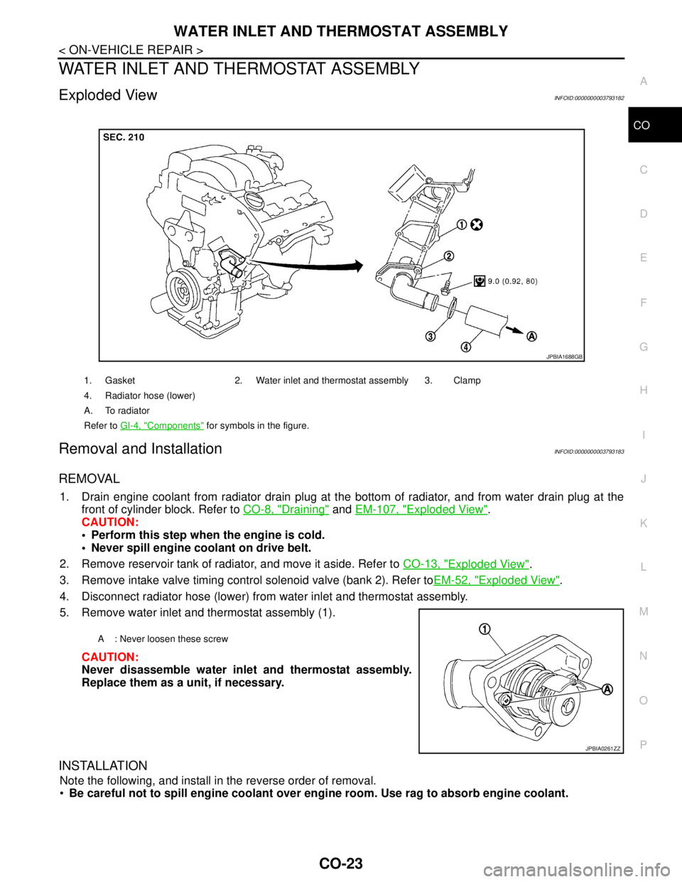
Exploded ViewINFOID:0000000003793182
Removal and InstallationINFOID:0000000003793183
REMOVAL
1. Drain engine coolant from radiator drain plug at the bottom of radiator, and from water drain plug at the
front of cylinder block. Refer to CO-8, "
Draining" and EM-107, "Exploded View".
CAUTION:
Perform this step when the engine is cold.
Never spill engine coolant on drive belt.
2. Remove reservoir tank of radiator, and move it aside. Refer to CO-13, "
Exploded View".
3. Remove intake valve timing control solenoid valve (bank 2). Refer toEM-52, "
Exploded View".
4. Disconnect radiator hose (lower) from water inlet and thermostat assembly.
5. Remove water inlet and thermostat assembly (1).
CAUTION:
Never disassemble water inlet and thermostat assembly.
Replace them as a unit, if necessary.
INSTALLATION
Note the following, and install in the reverse order of removal.
Be careful not to spill engine coolant over engine room. Use rag to absorb engine coolant.
1. Gasket 2. Water inlet and thermostat assembly 3. Clamp
4. Radiator hose (lower)
A. To radiator
Refer to GI-4, "
Components" for symbols in the figure.
JPBIA1688GB
A : Never loosen these screw
JPBIA0261ZZ