2008 NISSAN TEANA bulb
[x] Cancel search: bulbPage 2903 of 5121
INL-24
< COMPONENT DIAGNOSIS >
STEP LAMP CIRCUIT
STEP LAMP CIRCUIT
DescriptionINFOID:0000000003774561
Controls the step lamp (ground side) to turn the step lamp ON and OFF.
Component Function CheckINFOID:0000000003774562
CAUTION:
Before performing the diagnosis, check that the following is normal.
Interior room lamp power supply
Step lamp bulb
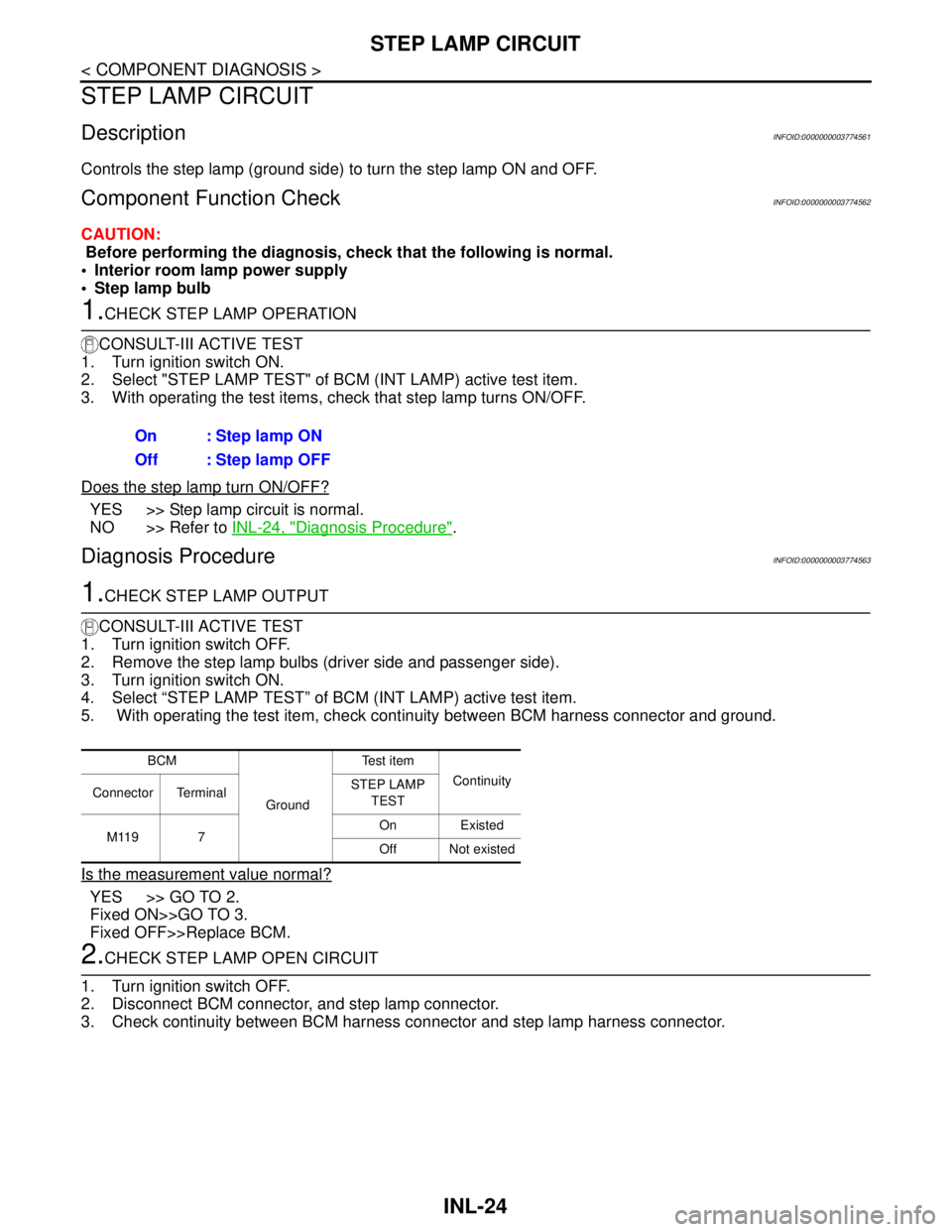
1.CHECK STEP LAMP OPERATION
CONSULT-III ACTIVE TEST
1. Turn ignition switch ON.
2. Select "STEP LAMP TEST" of BCM (INT LAMP) active test item.
3. With operating the test items, check that step lamp turns ON/OFF.
Does the step lamp turn ON/OFF?
YES >> Step lamp circuit is normal.
NO >> Refer to INL-24, "
Diagnosis Procedure".
Diagnosis ProcedureINFOID:0000000003774563
1.CHECK STEP LAMP OUTPUT
CONSULT-III ACTIVE TEST
1. Turn ignition switch OFF.
2. Remove the step lamp bulbs (driver side and passenger side).
3. Turn ignition switch ON.
4. Select “STEP LAMP TEST” of BCM (INT LAMP) active test item.
5. With operating the test item, check continuity between BCM harness connector and ground.
Is the measurement value normal?
YES >> GO TO 2.
Fixed ON>>GO TO 3.
Fixed OFF>>Replace BCM.
2.CHECK STEP LAMP OPEN CIRCUIT
1. Turn ignition switch OFF.
2. Disconnect BCM connector, and step lamp connector.
3. Check continuity between BCM harness connector and step lamp harness connector. On : Step lamp ON
Off : Step lamp OFF
BCM
GroundTe s t i t e m
Continuity
Connector TerminalSTEP LAMP
TEST
M119 7On Existed
Off Not existed
Page 2905 of 5121
INL-26
< COMPONENT DIAGNOSIS >
TRUNK ROOM LAMP CIRCUIT
TRUNK ROOM LAMP CIRCUIT
DescriptionINFOID:0000000003812232
Controls the trunk room lamp (ground side) to turn the trunk room lamp ON and OFF.
Component Function CheckINFOID:0000000003812233
CAUTION:
Before performing the diagnosis, check that the following is normal.
Interior room lamp power supply
Trunk room lamp bulb
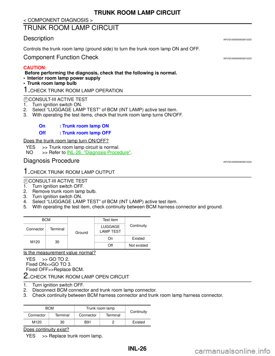
1.CHECK TRUNK ROOM LAMP OPERATION
CONSULT-III ACTIVE TEST
1. Turn ignition switch ON.
2. Select “LUGGAGE LAMP TEST” of BCM (INT LAMP) active test item.
3. With operating the test items, check that trunk room lamp turns ON/OFF.
Does the trunk room lamp turn ON/OFF?
YES >> Trunk room lamp circuit is normal.
NO >> Refer to INL-26, "
Diagnosis Procedure".
Diagnosis ProcedureINFOID:0000000003812234
1.CHECK TRUNK ROOM LAMP OUTPUT
CONSULT-III ACTIVE TEST
1. Turn ignition switch OFF.
2. Remove trunk room lamp bulb.
3. Turn ignition switch ON.
4. Select “LUGGAGE LAMP TEST” of BCM (INT LAMP) active test item.
5. With operating the test item, check continuity between BCM harness connector and ground.
Is the measurement value normal?
YES >> GO TO 2.
Fixed ON>>GO TO 3.
Fixed OFF>>Replace BCM.
2.CHECK TRUNK ROOM LAMP OPEN CIRCUIT
1. Turn ignition switch OFF.
2. Disconnect BCM connector and trunk room lamp connector.
3. Check continuity between BCM harness connector and trunk room lamp harness connector.
Does continuity exist?
YES >> Replace trunk room lamp.On : Trunk room lamp ON
Off : Trunk room lamp OFF
BCM
GroundTe s t i t e m
Continuity
Connector TerminalLUGGAGE
LAMP TEST
M120 30On Existed
Off Not existed
BCM Trunk room lamp
Continuity
Connector Terminal Connector Terminal
M120 30 B91 2 Existed
Page 2963 of 5121
INL-84
< ECU DIAGNOSIS >
BCM (BODY CONTROL MODULE)
HIGH FLASHER OPERATION
BCM detects the turn signal lamp circuit status by the current value.
BCM increases the turn signal lamp blinking speed if the bulb or harness open is detected with the turn signal
lamp operating.
NOTE:
The blinking speed is normal while activating the hazard warning lamp.
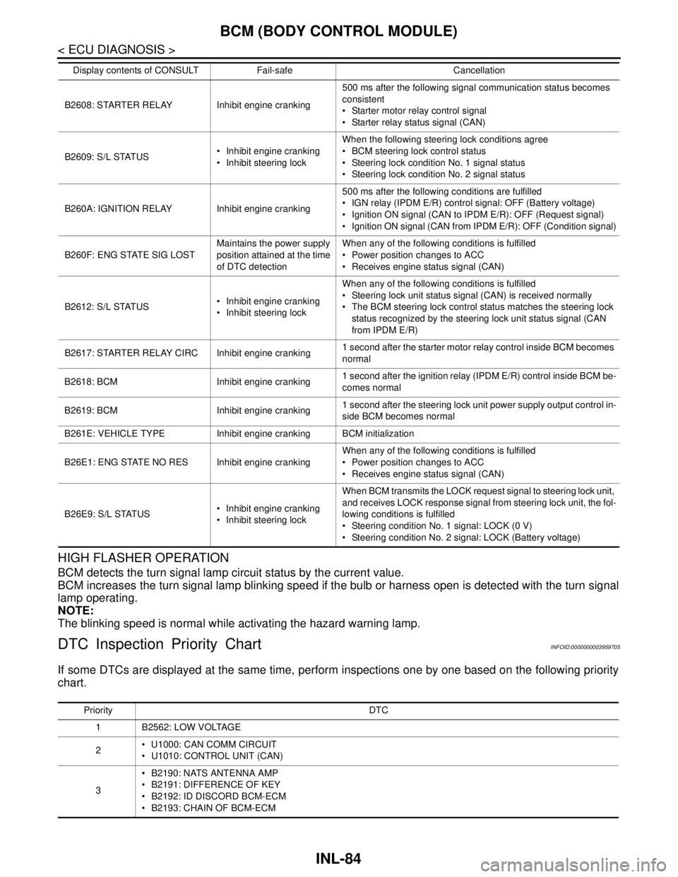
DTC Inspection Priority ChartINFOID:0000000003959705
If some DTCs are displayed at the same time, perform inspections one by one based on the following priority
chart.
B2608: STARTER RELAY Inhibit engine cranking500 ms after the following signal communication status becomes
consistent
Starter motor relay control signal
Starter relay status signal (CAN)
B2609: S/L STATUS Inhibit engine cranking
Inhibit steering lockWhen the following steering lock conditions agree
BCM steering lock control status
Steering lock condition No. 1 signal status
Steering lock condition No. 2 signal status
B260A: IGNITION RELAY Inhibit engine cranking500 ms after the following conditions are fulfilled
IGN relay (IPDM E/R) control signal: OFF (Battery voltage)
Ignition ON signal (CAN to IPDM E/R): OFF (Request signal)
Ignition ON signal (CAN from IPDM E/R): OFF (Condition signal)
B260F: ENG STATE SIG LOSTMaintains the power supply
position attained at the time
of DTC detectionWhen any of the following conditions is fulfilled
Power position changes to ACC
Receives engine status signal (CAN)
B2612: S/L STATUS Inhibit engine cranking
Inhibit steering lockWhen any of the following conditions is fulfilled
Steering lock unit status signal (CAN) is received normally
The BCM steering lock control status matches the steering lock
status recognized by the steering lock unit status signal (CAN
from IPDM E/R)
B2617: STARTER RELAY CIRC Inhibit engine cranking1 second after the starter motor relay control inside BCM becomes
normal
B2618: BCM Inhibit engine cranking1 second after the ignition relay (IPDM E/R) control inside BCM be-
comes normal
B2619: BCM Inhibit engine cranking1 second after the steering lock unit power supply output control in-
side BCM becomes normal
B261E: VEHICLE TYPE Inhibit engine cranking BCM initialization
B26E1: ENG STATE NO RES Inhibit engine crankingWhen any of the following conditions is fulfilled
Power position changes to ACC
Receives engine status signal (CAN)
B26E9: S/L STATUS Inhibit engine cranking
Inhibit steering lockWhen BCM transmits the LOCK request signal to steering lock unit,
and receives LOCK response signal from steering lock unit, the fol-
lowing conditions is fulfilled
Steering condition No. 1 signal: LOCK (0 V)
Steering condition No. 2 signal: LOCK (Battery voltage) Display contents of CONSULT Fail-safe Cancellation
Priority DTC
1 B2562: LOW VOLTAGE
2 U1000: CAN COMM CIRCUIT
U1010: CONTROL UNIT (CAN)
3 B2190: NATS ANTENNA AMP
B2191: DIFFERENCE OF KEY
B2192: ID DISCORD BCM-ECM
B2193: CHAIN OF BCM-ECM
Page 2966 of 5121

INTERIOR LIGHTING SYSTEM SYMPTOMS
INL-87
< SYMPTOM DIAGNOSIS >
C
D
E
F
G
H
I
J
K
MA
B
INL
N
O
P
SYMPTOM DIAGNOSIS
INTERIOR LIGHTING SYSTEM SYMPTOMS
Symptom TableINFOID:0000000003774578
CAUTION:
Perform the self-diagnosis with CONSULT-III before the symptom diagnosis. Perform the trouble diag-
nosis if any DTC is detected.
Symptom Possible cause Inspection item
All the following lamps are not turned ON.
Map lamp
Personal lamp
Trunk room lamp
Step lamp
Vanity mirror lamp Harness between BCM and each
interior room lamp
BCMInterior room lamp power supply cir-
cuit
Refer to INL-20
.
Interior room lamp is not
turned ON even though
the door is open.
(It turns ON when turning
the interior room lamp
ON.)
Interior room lamp does
not turn OFF even though
the door is closed.Map lamp and personal
lamp Harness between BCM and each
door switch
Harness between BCM and map
lamp
BCMDoor switch circuit
Refer to DLK-57
.
Interior room lamp control circuit
Refer to INL-22
.
Only the map lamp Map lamp bulb
Map lamp assembly—
Only the personal lamp Personal lamp bulb
Personal lamp assembly—
Interior room lamp timer does not activate.
(It turns ON/OFF when the door opens/closes.)—Check the interior room lamp setting.
Refer to INL-16
.
Step lamps (driver side and passenger side) are not
turned ON.
(Map lamp and personal lamp are turned ON.) Harness between BCM and each
step lamp
BCMStep lamp circuit
Refer to INL-24
.
Step lamps (driver side and passenger side) are not
turned OFF.
(Map lamp and personal lamp are turned OFF.)
Trunk room lamp does not turn ON.
(The bulb is normal.)
Trunk room lamp does not turn OFF. Harness between BCM and trunk
room lamp switch
Harness between BCM and trunk
room lamp
BCMTrunk room lamp switch circuit
Refer toDLK-70
.
Trunk room lamp circuit
Refer to INL-26
.
Push-button ignition switch illumination does not illu-
minate. Harness between BCM and push-
button ignition switch
BCMPush-button ignition switch illumina-
tion circuit
Refer to INL-28
.
Interior room lamp battery saver does not activate. —Check the interior room lamp battery
saver setting.
Refer to INL-17
.
Page 2968 of 5121
MAP LAMP
INL-89
< ON-VEHICLE REPAIR >
C
D
E
F
G
H
I
J
K
MA
B
INL
N
O
P
ON-VEHICLE REPAIR
MAP LAMP
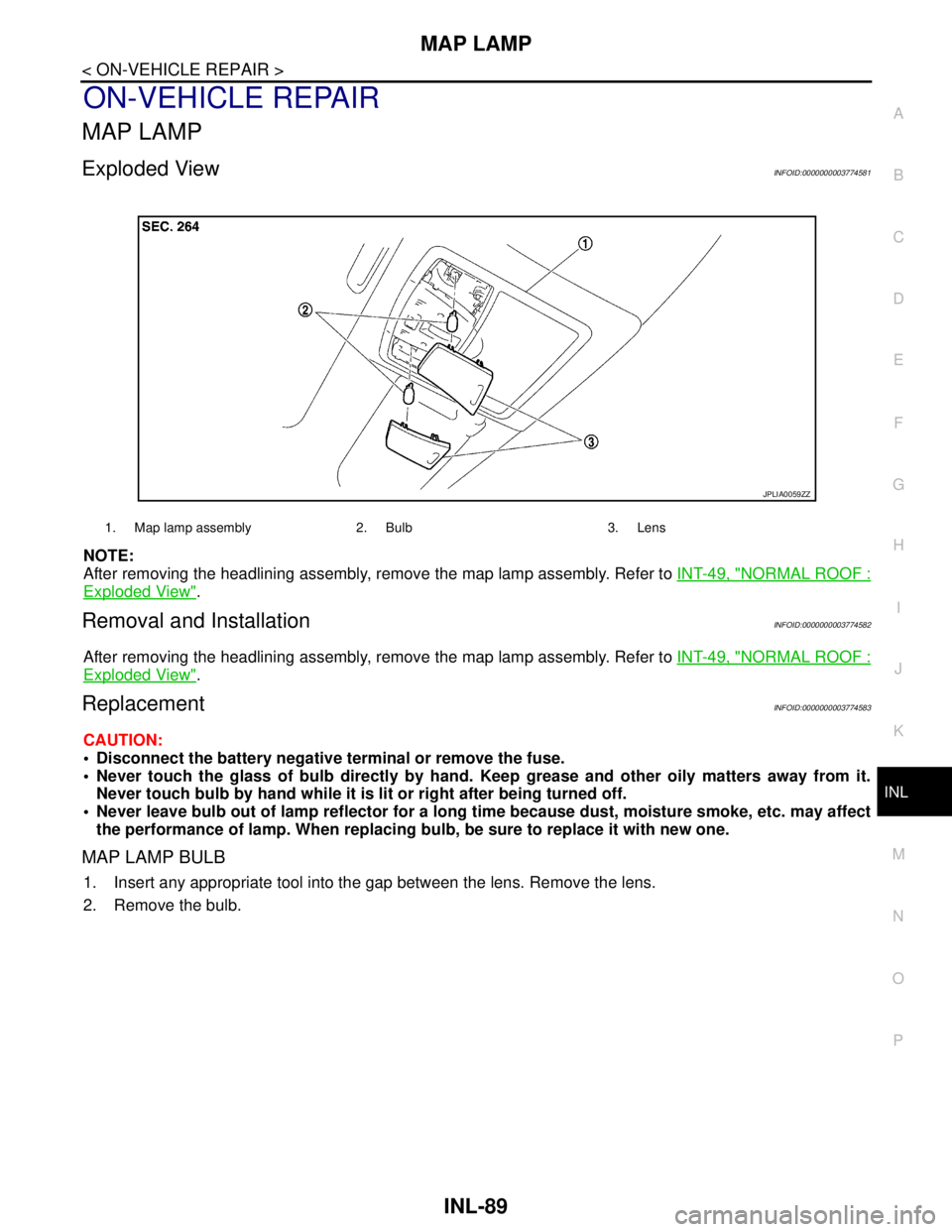
Exploded ViewINFOID:0000000003774581
NOTE:
After removing the headlining assembly, remove the map lamp assembly. Refer to INT-49, "
NORMAL ROOF :
Exploded View".
Removal and InstallationINFOID:0000000003774582
After removing the headlining assembly, remove the map lamp assembly. Refer to INT-49, "NORMAL ROOF :
Exploded View".
ReplacementINFOID:0000000003774583
CAUTION:
Disconnect the battery negative terminal or remove the fuse.
Never touch the glass of bulb directly by hand. Keep grease and other oily matters away from it.
Never touch bulb by hand while it is lit or right after being turned off.
Never leave bulb out of lamp reflector for a long time because dust, moisture smoke, etc. may affect
the performance of lamp. When replacing bulb, be sure to replace it with new one.
MAP LAMP BULB
1. Insert any appropriate tool into the gap between the lens. Remove the lens.
2. Remove the bulb.
1. Map lamp assembly 2. Bulb 3. Lens
JPLIA0059ZZ
Page 2971 of 5121
INL-92
< ON-VEHICLE REPAIR >
VANITY MIRROR LAMP
VANITY MIRROR LAMP
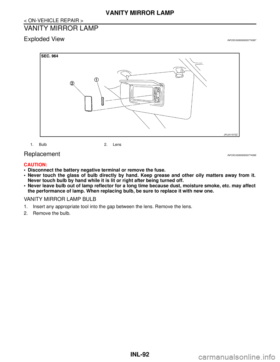
Exploded ViewINFOID:0000000003774587
ReplacementINFOID:0000000003774588
CAUTION:
Disconnect the battery negative terminal or remove the fuse.
Never touch the glass of bulb directly by hand. Keep grease and other oily matters away from it.
Never touch bulb by hand while it is lit or right after being turned off.
Never leave bulb out of lamp reflector for a long time because dust, moisture smoke, etc. may affect
the performance of lamp. When replacing bulb, be sure to replace it with new one.
VANITY MIRROR LAMP BULB
1. Insert any appropriate tool into the gap between the lens. Remove the lens.
2. Remove the bulb.
1. Bulb 2. Lens
JPLIA1107ZZ
Page 2972 of 5121
ASHTRAY ILLUMINATION
INL-93
< ON-VEHICLE REPAIR >
C
D
E
F
G
H
I
J
K
MA
B
INL
N
O
P
ASHTRAY ILLUMINATION
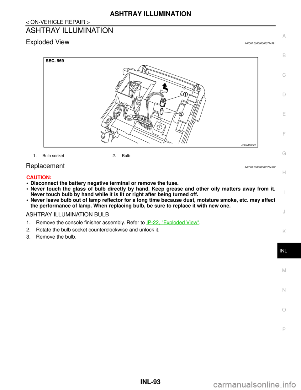
Exploded ViewINFOID:0000000003774591
ReplacementINFOID:0000000003774592
CAUTION:
Disconnect the battery negative terminal or remove the fuse.
Never touch the glass of bulb directly by hand. Keep grease and other oily matters away from it.
Never touch bulb by hand while it is lit or right after being turned off.
Never leave bulb out of lamp reflector for a long time because dust, moisture smoke, etc. may affect
the performance of lamp. When replacing bulb, be sure to replace it with new one.
ASHTRAY ILLUMINATION BULB
1. Remove the console finisher assembly. Refer to IP-22, "Exploded View".
2. Rotate the bulb socket counterclockwise and unlock it.
3. Remove the bulb.
1. Bulb socket 2. Bulb
JPLIA1183ZZ
Page 2973 of 5121
INL-94
< ON-VEHICLE REPAIR >
GLOVE BOX LAMP
GLOVE BOX LAMP
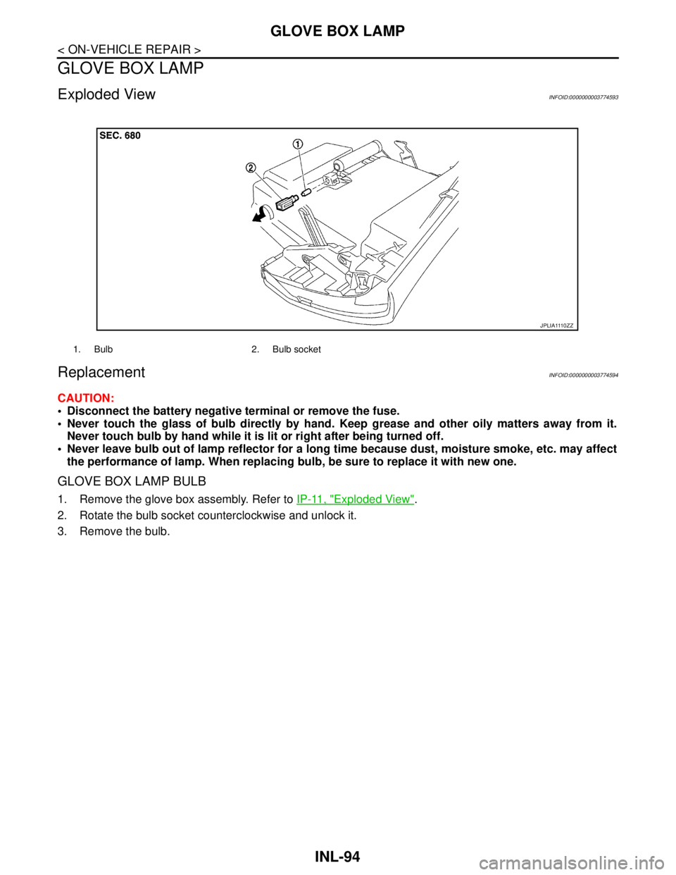
Exploded ViewINFOID:0000000003774593
ReplacementINFOID:0000000003774594
CAUTION:
Disconnect the battery negative terminal or remove the fuse.
Never touch the glass of bulb directly by hand. Keep grease and other oily matters away from it.
Never touch bulb by hand while it is lit or right after being turned off.
Never leave bulb out of lamp reflector for a long time because dust, moisture smoke, etc. may affect
the performance of lamp. When replacing bulb, be sure to replace it with new one.
GLOVE BOX LAMP BULB
1. Remove the glove box assembly. Refer to IP-11, "Exploded View".
2. Rotate the bulb socket counterclockwise and unlock it.
3. Remove the bulb.
1. Bulb 2. Bulb socket
J P L I A 111 0 Z Z