2008 NISSAN TEANA bulb
[x] Cancel search: bulbPage 2389 of 5121

EXL-360
< SERVICE DATA AND SPECIFICATIONS (SDS) [HALOGEN TYPE]
SERVICE DATA AND SPECIFICATIONS (SDS)
SERVICE DATA AND SPECIFICATIONS (SDS)
SERVICE DATA AND SPECIFICATIONS (SDS)
Bulb SpecificationsINFOID:0000000003773752
Item Type Wattage (W)
Front combination lampHeadlamp (HI) H9 65
Headlamp (LO) H11 55
Parking Lamp W5W 5
Front turn signal WY21W (Amber) 21
Front fog lamp H11 55
Front side turn signal lamp (integrated into the door mirror) LED —
Rear combination lampStop/tail lamp LED —
Rear turn signal lamp S25 (Amber) 21
Back-up lamp W16W 16
License plate lamp W5W 5
High-mounted stop lamp LED —
Rear fog lamp W21W 21
Page 2517 of 5121
GI-24
< PRECAUTION >
PRECAUTIONS
PRECAUTION
PRECAUTIONS
DescriptionINFOID:0000000003852776
Observe the following precautions to ensure safe and proper servicing. These precautions are not
described in each individual section.
Precaution for Supplemental Restraint System (SRS) "AIR BAG" and "SEAT BELT
PRE-TENSIONER"
INFOID:0000000003852830
The Supplemental Restraint System such as “AIR BAG” and “SEAT BELT PRE-TENSIONER”, used along
with a front seat belt, helps to reduce the risk or severity of injury to the driver and front passenger for certain
types of collision. Information necessary to service the system safely is included in the “SRS AIRBAG” and
“SEAT BELT” of this Service Manual.
WARNING:
To avoid rendering the SRS inoperative, which could increase the risk of personal injury or death in
the event of a collision which would result in air bag inflation, all maintenance must be performed by
an authorized NISSAN/INFINITI dealer.
Improper maintenance, including incorrect removal and installation of the SRS, can lead to personal
injury caused by unintentional activation of the system. For removal of Spiral Cable and Air Bag
Module, see the “SRS AIRBAG”.
Never use electrical test equipment on any circuit related to the SRS unless instructed to in this Ser-
vice Manual. SRS wiring harnesses can be identified by yellow and/or orange harnesses or harness
connectors.
Precautions For Xenon Headlamp ServiceINFOID:0000000003852778
WARNING:
Comply with the following warnings to prevent any serious accident.
Disconnect the battery cable (negative terminal) or the power supply fuse before installing, remov-
ing, or touching the xenon headlamp (bulb included). The xenon headlamp contains high-voltage
generated parts.
Never work with wet hands.
Check the xenon headlamp ON-OFF status after assembling it to the vehicle. Never turn the xenon
headlamp ON in other conditions. Connect the power supply to the vehicle-side connector.
(Turning it ON outside the lamp case may cause fire or visual impairments.)
Never touch the bulb glass immediately after turning it OFF. It is extremely hot.
CAUTION:
Comply with the following cautions to prevent any error and malfunction.
Install the xenon bulb securely. (Insufficient bulb socket installation may melt the bulb, the connec-
tor, the housing, etc. by high-voltage leakage or corona discharge.)
Never perform HID circuit inspection with a tester.
Never touch the xenon bulb glass with hands. Never put oil and grease on it.
Dispose of the used xenon bulb after packing it in thick vinyl without breaking it.
Never wipe out dirt and contamination with organic solvent (thinner, gasoline, etc.).
Precaution Necessary for Steering Wheel Rotation after Battery Disconnect
INFOID:0000000003852856
NOTE:
Before removing and installing any control units, first turn the push-button ignition switch to the LOCK posi-
tion, then disconnect both battery cables.
After finishing work, confirm that all control unit connectors are connected properly, then re-connect both
battery cables.
Always use CONSULT-III to perform self-diagnosis as a part of each function inspection after finishing work.
If a DTC is detected, perform trouble diagnosis according to self-diagnosis results.
This vehicle is equipped with a push-button ignition switch and a steering lock unit.
If the battery is disconnected or discharged, the steering wheel will lock and cannot be turned.
Page 2533 of 5121

GI-40
< BASIC INSPECTION >
SERVICE INFORMATION FOR ELECTRICAL INCIDENT
For detailed ground distribution information, refer to “Ground Distribution” in PG section.
VOLTAGE DROP TESTS
Voltage drop tests are often used to find components or circuits which have excessive resistance. A voltage
drop in a circuit is caused by a resistance when the circuit is in operation.
Check the wire in the illustration. When measuring resistance with DMM, contact by a single strand of wire
will give reading of 0 ohms. This would indicate a good circuit. When the circuit operates, this single strand
of wire is not able to carry the current. The single strand will have a high resistance to the current. This will
be picked up as a slight voltage drop.
Unwanted resistance can be caused by many situations as follows:
- Undersized wiring (single strand example)
- Corrosion on switch contacts
- Loose wire connections or splices.
If repairs are needed always use wire that is of the same or larger gauge.
Measuring Voltage Drop — Accumulated Method
Connect the DMM across the connector or part of the circuit you want to check. The positive lead of the
DMM should be closer to power and the negative lead closer to ground.
Operate the circuit.
The DMM will indicate how many volts are being used to “push” current through that part of the circuit.
Note in the illustration that there is an excessive 4.1 volt drop between the battery and the bulb.
Measuring Voltage Drop — Steb-by-Step
The step-by-step method is most useful for isolating excessive drops in low voltage systems (such as those
in “Computer Controlled Systems”).
Circuits in the “Computer Controlled System” operate on very low amperage.
SGI853
SGI974
Page 2582 of 5121
PRECAUTIONS
HA-13
< PRECAUTION >
C
D
E
F
G
H
J
K
L
MA
B
HA
N
O
P
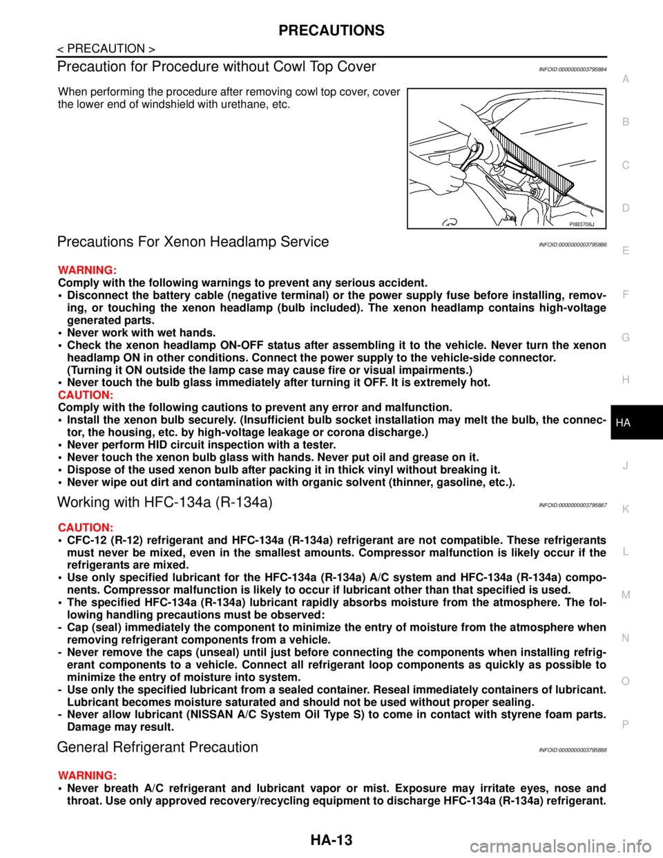
Precaution for Procedure without Cowl Top CoverINFOID:0000000003795884
When performing the procedure after removing cowl top cover, cover
the lower end of windshield with urethane, etc.
Precautions For Xenon Headlamp ServiceINFOID:0000000003795886
WARNING:
Comply with the following warnings to prevent any serious accident.
Disconnect the battery cable (negative terminal) or the power supply fuse before installing, remov-
ing, or touching the xenon headlamp (bulb included). The xenon headlamp contains high-voltage
generated parts.
Never work with wet hands.
Check the xenon headlamp ON-OFF status after assembling it to the vehicle. Never turn the xenon
headlamp ON in other conditions. Connect the power supply to the vehicle-side connector.
(Turning it ON outside the lamp case may cause fire or visual impairments.)
Never touch the bulb glass immediately after turning it OFF. It is extremely hot.
CAUTION:
Comply with the following cautions to prevent any error and malfunction.
Install the xenon bulb securely. (Insufficient bulb socket installation may melt the bulb, the connec-
tor, the housing, etc. by high-voltage leakage or corona discharge.)
Never perform HID circuit inspection with a tester.
Never touch the xenon bulb glass with hands. Never put oil and grease on it.
Dispose of the used xenon bulb after packing it in thick vinyl without breaking it.
Never wipe out dirt and contamination with organic solvent (thinner, gasoline, etc.).
Working with HFC-134a (R-134a)INFOID:0000000003795887
CAUTION:
CFC-12 (R-12) refrigerant and HFC-134a (R-134a) refrigerant are not compatible. These refrigerants
must never be mixed, even in the smallest amounts. Compressor malfunction is likely occur if the
refrigerants are mixed.
Use only specified lubricant for the HFC-134a (R-134a) A/C system and HFC-134a (R-134a) compo-
nents. Compressor malfunction is likely to occur if lubricant other than that specified is used.
The specified HFC-134a (R-134a) lubricant rapidly absorbs moisture from the atmosphere. The fol-
lowing handling precautions must be observed:
- Cap (seal) immediately the component to minimize the entry of moisture from the atmosphere when
removing refrigerant components from a vehicle.
- Never remove the caps (unseal) until just before connecting the components when installing refrig-
erant components to a vehicle. Connect all refrigerant loop components as quickly as possible to
minimize the entry of moisture into system.
- Use only the specified lubricant from a sealed container. Reseal immediately containers of lubricant.
Lubricant becomes moisture saturated and should not be used without proper sealing.
- Never allow lubricant (NISSAN A/C System Oil Type S) to come in contact with styrene foam parts.
Damage may result.
General Refrigerant PrecautionINFOID:0000000003795888
WARNING:
Never breath A/C refrigerant and lubricant vapor or mist. Exposure may irritate eyes, nose and
throat. Use only approved recovery/recycling equipment to discharge HFC-134a (R-134a) refrigerant.
PIIB3706J
Page 2726 of 5121

HAC-98
< PRECAUTION >[WITHOUT 7 INCH DISPLAY]
PRECAUTIONS
Precaution for Procedure without Cowl Top Cover
INFOID:0000000003846397
When performing the procedure after removing cowl top cover, cover
the lower end of windshield with urethane, etc.
Precautions For Xenon Headlamp ServiceINFOID:0000000003846398
WARNING:
Comply with the following warnings to prevent any serious accident.
Disconnect the battery cable (negative terminal) or the power supply fuse before installing, remov-
ing, or touching the xenon headlamp (bulb included). The xenon headlamp contains high-voltage
generated parts.
Never work with wet hands.
Check the xenon headlamp ON-OFF status after assembling it to the vehicle. Never turn the xenon
headlamp ON in other conditions. Connect the power supply to the vehicle-side connector.
(Turning it ON outside the lamp case may cause fire or visual impairments.)
Never touch the bulb glass immediately after turning it OFF. It is extremely hot.
CAUTION:
Comply with the following cautions to prevent any error and malfunction.
Install the xenon bulb securely. (Insufficient bulb socket installation may melt the bulb, the connec-
tor, the housing, etc. by high-voltage leakage or corona discharge.)
Never perform HID circuit inspection with a tester.
Never touch the xenon bulb glass with hands. Never put oil and grease on it.
Dispose of the used xenon bulb after packing it in thick vinyl without breaking it.
Never wipe out dirt and contamination with organic solvent (thinner, gasoline, etc.).
Working with HFC-134a (R-134a)INFOID:0000000003846399
CAUTION:
CFC-12 (R-12) refrigerant and HFC-134a (R-134a) refrigerant are not compatible. Compressor mal-
function is likely to occur if the refrigerants are mixed, refer to “CONTAMINATED REFRIGERANT”
below. To determine the purity of HFC-134a (R-134a) in the vehicle and recovery tank, use Refriger-
ant Recovery/Recycling Recharging equipment and Refrigerant Identifier.
Use only specified lubricant for the HFC-134a (R-134a) A/C system and HFC-134a (R-134a) compo-
nents. Compressor malfunction is likely to occur if lubricant other than that specified is used.
The specified HFC-134a (R-134a) lubricant rapidly absorbs moisture from the atmosphere. The fol-
lowing handling precautions must be observed:
- Immediately cap (seal) the component to minimize the entry of moisture from the atmosphere when
removing refrigerant components from a vehicle.
- Never remove the caps (unseal) until just before connecting the components when installing refrig-
erant components to a vehicle. Connect all refrigerant loop components as quickly as possible to
minimize the entry of moisture into system.
- Use only the specified lubricant from a sealed container. Immediately reseal containers of lubricant.
Lubricant becomes moisture saturated and should not be used without proper sealing.
- Never allow lubricant (NISSAN A/C System Oil Type S) to come in to contact with styrene foam parts.
Damage may result.
CONTAMINATED REFRIGERANT
Take the appropriate steps shown below if a refrigerant other than pure HFC-134a (R-134a) is identified
in a vehicle:
Explain to the customer that environmental regulations prohibit the release of contaminated refrigerant into
the atmosphere.
PIIB3706J
Page 2866 of 5121

HAC-238
< PRECAUTION >[WITH 7 INCH DISPLAY]
PRECAUTIONS
Precaution for Procedure without Cowl Top Cover
INFOID:0000000003884814
When performing the procedure after removing cowl top cover, cover
the lower end of windshield with urethane, etc.
Precautions For Xenon Headlamp ServiceINFOID:0000000003884815
WARNING:
Comply with the following warnings to prevent any serious accident.
Disconnect the battery cable (negative terminal) or the power supply fuse before installing, remov-
ing, or touching the xenon headlamp (bulb included). The xenon headlamp contains high-voltage
generated parts.
Never work with wet hands.
Check the xenon headlamp ON-OFF status after assembling it to the vehicle. Never turn the xenon
headlamp ON in other conditions. Connect the power supply to the vehicle-side connector.
(Turning it ON outside the lamp case may cause fire or visual impairments.)
Never touch the bulb glass immediately after turning it OFF. It is extremely hot.
CAUTION:
Comply with the following cautions to prevent any error and malfunction.
Install the xenon bulb securely. (Insufficient bulb socket installation may melt the bulb, the connec-
tor, the housing, etc. by high-voltage leakage or corona discharge.)
Never perform HID circuit inspection with a tester.
Never touch the xenon bulb glass with hands. Never put oil and grease on it.
Dispose of the used xenon bulb after packing it in thick vinyl without breaking it.
Never wipe out dirt and contamination with organic solvent (thinner, gasoline, etc.).
Working with HFC-134a (R-134a)INFOID:0000000003884816
CAUTION:
CFC-12 (R-12) refrigerant and HFC-134a (R-134a) refrigerant are not compatible. Compressor mal-
function is likely to occur if the refrigerants are mixed, refer to “CONTAMINATED REFRIGERANT”
below. To determine the purity of HFC-134a (R-134a) in the vehicle and recovery tank, use Refriger-
ant Recovery/Recycling Recharging equipment and Refrigerant Identifier.
Use only specified lubricant for the HFC-134a (R-134a) A/C system and HFC-134a (R-134a) compo-
nents. Compressor malfunction is likely to occur if lubricant other than that specified is used.
The specified HFC-134a (R-134a) lubricant rapidly absorbs moisture from the atmosphere. The fol-
lowing handling precautions must be observed:
- Immediately cap (seal) the component to minimize the entry of moisture from the atmosphere when
removing refrigerant components from a vehicle.
- Never remove the caps (unseal) until just before connecting the components when installing refrig-
erant components to a vehicle. Connect all refrigerant loop components as quickly as possible to
minimize the entry of moisture into system.
- Use only the specified lubricant from a sealed container. Immediately reseal containers of lubricant.
Lubricant becomes moisture saturated and should not be used without proper sealing.
- Never allow lubricant (NISSAN A/C System Oil Type S) to come in to contact with styrene foam parts.
Damage may result.
CONTAMINATED REFRIGERANT
Take the appropriate steps shown below if a refrigerant other than pure HFC-134a (R-134a) is identified
in a vehicle:
Explain to the customer that environmental regulations prohibit the release of contaminated refrigerant into
the atmosphere.
PIIB3706J
Page 2881 of 5121
INL-2
BCM (BODY CONTROL MODULE) ..................53
Reference Value .....................................................53
Wiring Diagram - BCM - .........................................76
Fail-safe ..................................................................82
DTC Inspection Priority Chart ..............................84
DTC Index ..............................................................85
SYMPTOM DIAGNOSIS .............................87
INTERIOR LIGHTING SYSTEM SYMPTOMS ...87
Symptom Table ......................................................87
PRECAUTION .............................................88
PRECAUTIONS .................................................88
Precaution for Supplemental Restraint System
(SRS) "AIR BAG" and "SEAT BELT PRE-TEN-
SIONER" .................................................................
88
ON-VEHICLE REPAIR ................................89
MAP LAMP ........................................................89
Exploded View ........................................................89
Removal and Installation ........................................89
Replacement ..........................................................89
MOOD LAMP .....................................................90
MAP LAMP ................................................................90
MAP LAMP : Exploded View ..................................90
FRONT DOOR GRIP .................................................90
FRONT DOOR GRIP : Exploded View ...................90
FRONT DOOR GRIP : Replacement ......................90
REAR DOOR GRIP ...................................................90
REAR DOOR GRIP : Exploded View .....................91
REAR DOOR GRIP : Replacement ........................91
VANITY MIRROR LAMP ...................................92
Exploded View ........................................................92
Replacement ...........................................................92
ASHTRAY ILLUMINATION ...............................93
Exploded View ........................................................93
Replacement ...........................................................93
GLOVE BOX LAMP ...........................................94
Exploded View ........................................................94
Replacement ...........................................................94
STEP LAMP .......................................................95
Exploded View ........................................................95
Removal and Installation .........................................95
Replacement ...........................................................95
PERSONAL LAMP ............................................96
Exploded View ........................................................96
Removal and Installation .........................................96
Replacement ...........................................................96
TRUNK ROOM LAMP .......................................97
Exploded View ........................................................97
Removal and Installation .........................................97
Replacement ...........................................................97
SERVICE DATA AND SPECIFICATIONS
(SDS) ..........................................................
98
SERVICE DATA AND SPECIFICATIONS
(SDS) .................................................................
98
Bulb Specifications ..................................................98
Page 2901 of 5121
INL-22
< COMPONENT DIAGNOSIS >
INTERIOR ROOM LAMP CONTROL CIRCUIT
INTERIOR ROOM LAMP CONTROL CIRCUIT
DescriptionINFOID:0000000003774558
Controls each interior room lamp (ground side) by PWM signal.
NOTE:
PWM signal control period is approximately 250 Hz (in the gradual brightening/dimming).
Component Function CheckINFOID:0000000003774559
NOTE:
Replace the personal lamp assembly if the map lamp is turned ON but the personal lamp LH and RH are not
turn ON.
CAUTION:
Before performing the diagnosis, check that the following is normal.
• Interior room lamp power supply
Map lamp bulb
Personal lamp bulb
1.CHECK INTERIOR ROOM LAMP CONTROL FUNCTION
CONSULT-III ACTIVE TEST
1. Switch the map lamp switch to DOOR.
2. Turn ignition switch ON.
3. Select “INT LAMP” of BCM (INT LAMP) active test item.
4. With operating the test items, check that each interior room lamp turns ON/OFF (gradual brightening/dim-
ming).
Does the interior room lamp turns ON/OFF (gradual brightening/dimming)?
YES >> Interior room lamp control circuit is normal.
NO >> Refer to INL-22, "
Diagnosis Procedure".
Diagnosis ProcedureINFOID:0000000003774560
1.CHECK INTERIOR ROOM LAMP CONTROL OUTPUT
CONSULT-III ACTIVE TEST
1. Turn ignition switch OFF.
2. Remove all the bulbs of map lamp and personal lamp.
3. Select “INT LAMP” of BCM (INT LAMP) active test item.
4. With operating the test item, check continuity between BCM harness connector and ground.
Is the measurement value normal?
YES >> GO TO 2.
Fixed ON>>GO TO 3.
Fixed OFF>>Replace BCM.
2.CHECK INTERIOR ROOM LAMP CONTROL OPEN CIRCUIT
1. Turn ignition switch OFF.
2. Disconnect BCM connector and map lamp connector.
3. Check continuity between BCM harness connector and map lamp harness connector. On : Interior room lamp gradual brightening
Off : Interior room lamp gradual dimming
BCM
GroundTe s t i t e m
Continuity
Connector Terminal INT LAMP
M119 19On Existed
Off Not existed