Page 3215 of 5121
CHASSIS MAINTENANCE
MA-27
< ON-VEHICLE MAINTENANCE >
C
D
E
F
G
H
I
J
K
L
MB
MAN
OA
Unit: mm (in)
HEADLAMP AIMING ADJUSTMENT (HALOGEN TYPE)
HEADLAMP AIMING ADJUSTMENT (HALOGEN TYPE) : DescriptionINFOID:0000000003862423
PREPARATION BEFORE ADJUSTING
NOTE:
For details, refer to the regulations in your own country.
Perform aiming if the vehicle front body has been repaired and/or the headlamp assembly has been
replaced.
Before performing aiming adjustment, check the following.
Adjust the tire pressure to the specification.
Fill with fuel, engine coolant and each oil.
Maintain the unloaded vehicle condition. (Remove luggage from the passenger compartment and the trunk
room.)
NOTE:
Do not remove the temporary tire, jack and on-vehicle tool.
Wipe out dirt on the headlamp.
CAUTION:
Never use organic solvent (thinner, gasoline etc.)
Ride alone on the driver seat.
Headlamp aiming switch sets to “0”.
AIMING ADJUSTMENT SCREW
Aiming adjustment area
Vertical direction (Y)
(Lower side from headlamp center height)Lateral direction (X)
(Right and left side from headlamp centerline)
Highest light axis 106 (4.17)
0-100 (3.94) Target light axis 120 (4.72)
Lowest light axis 164 (6.46)
Page 3218 of 5121
MA-30
< ON-VEHICLE MAINTENANCE >
CHASSIS MAINTENANCE
Unit: mm (in)
HEADLAMP AIMING ADJUSTMENT (HALOGEN TYPE) : Aiming Adjustment Proce-
dure (High Beam)
INFOID:0000000003862425
1. Place the screen.
NOTE:
Stop the vehicle at the perpendicular angle to the wall.
Set the screen so that it is perpendicular to a level load surface.
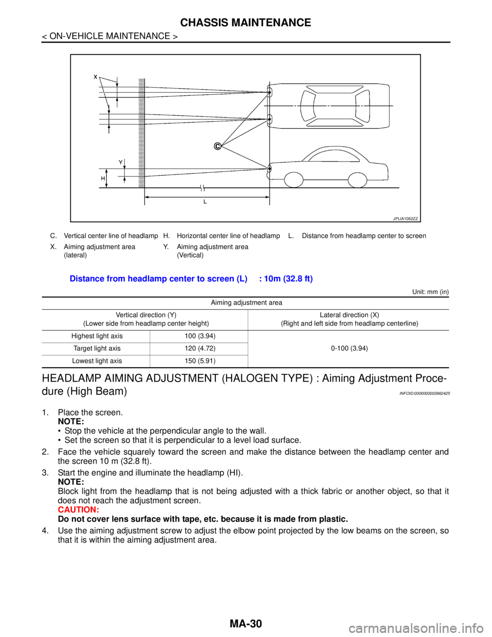
2. Face the vehicle squarely toward the screen and make the distance between the headlamp center and
the screen 10 m (32.8 ft).
3. Start the engine and illuminate the headlamp (HI).
NOTE:
Block light from the headlamp that is not being adjusted with a thick fabric or another object, so that it
does not reach the adjustment screen.
CAUTION:
Do not cover lens surface with tape, etc. because it is made from plastic.
4. Use the aiming adjustment screw to adjust the elbow point projected by the low beams on the screen, so
that it is within the aiming adjustment area.
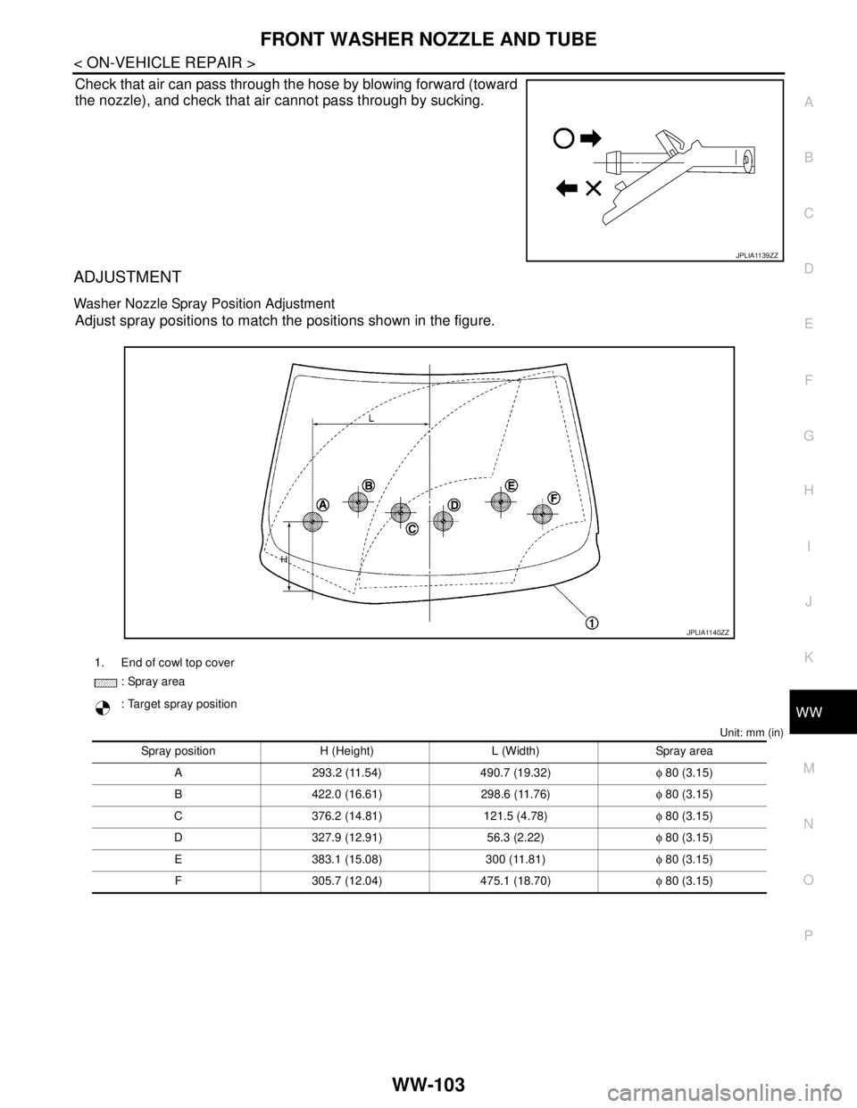
C. Vertical center line of headlamp H. Horizontal center line of headlamp L. Distance from headlamp center to screen
X. Aiming adjustment area
(lateral)Y. Aiming adjustment area
(Vertical)
Distance from headlamp center to screen (L) : 10m (32.8 ft)
Aiming adjustment area
Vertical direction (Y)
(Lower side from headlamp center height)Lateral direction (X)
(Right and left side from headlamp centerline)
Highest light axis 100 (3.94)
0-100 (3.94) Target light axis 120 (4.72)
Lowest light axis 150 (5.91)
JPLIA1062ZZ
Page 3219 of 5121
CHASSIS MAINTENANCE
MA-31
< ON-VEHICLE MAINTENANCE >
C
D
E
F
G
H
I
J
K
L
MB
MAN
OA
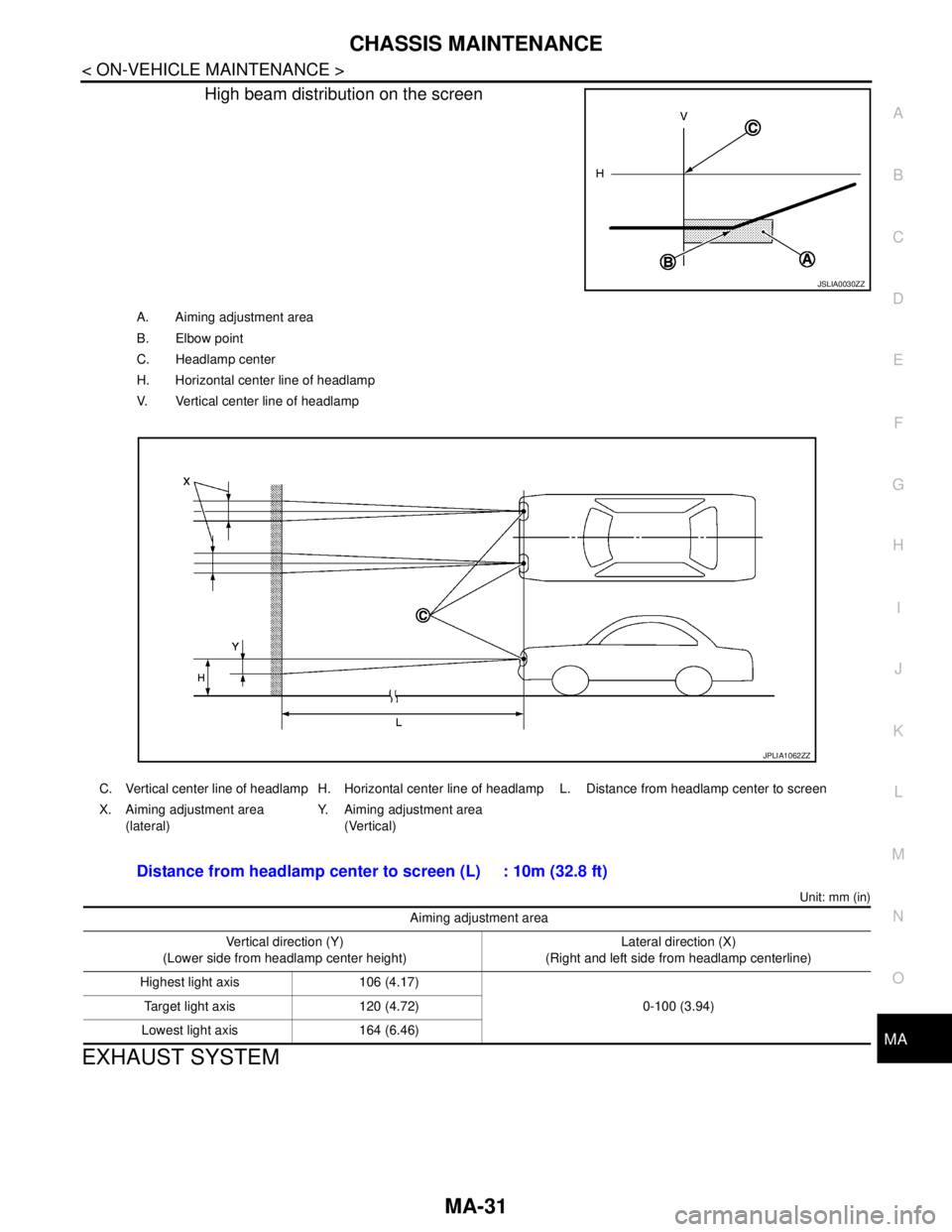
High beam distribution on the screen
Unit: mm (in)
EXHAUST SYSTEM
JSLIA0030ZZ
A. Aiming adjustment area
B. Elbow point
C. Headlamp center
H. Horizontal center line of headlamp
V. Vertical center line of headlamp
C. Vertical center line of headlamp H. Horizontal center line of headlamp L. Distance from headlamp center to screen
X. Aiming adjustment area
(lateral)Y. Aiming adjustment area
(Vertical)
Distance from headlamp center to screen (L) : 10m (32.8 ft)
Aiming adjustment area
Vertical direction (Y)
(Lower side from headlamp center height)Lateral direction (X)
(Right and left side from headlamp centerline)
Highest light axis 106 (4.17)
0-100 (3.94) Target light axis 120 (4.72)
Lowest light axis 164 (6.46)
JPLIA1062ZZ
Page 3833 of 5121

RSU-1
SUSPENSION
C
DF
G H
I
J
K L
M
SECTION RSU
A
B
RSU
N
O PCONTENTS
REAR SUSPENSION
SYMPTOM DIAGNOSIS ..... ..........................2
NOISE, VIBRATION AND HARSHNESS
(NVH) TROUBLESHOOTING ........................ .....
2
NVH Troubleshooting Chart ................................ ......2
PRECAUTION ...............................................3
PRECAUTIONS .............................................. .....3
Precautions for Suspension ................................ ......3
PREPARATION ............................................4
PREPARATION .............................................. .....4
Special Service Tool ........................................... ......4
ON-VEHICLE MAINTENANCE .....................5
REAR SUSPENSION ASSEMBLY ................ .....5
Inspection ............................................................ ......5
WHEEL ALIGNMENT ..........................................6
Inspection ............................................................ ......6
Adjustment ................................................................7
ON-VEHICLE REPAIR ..................................8
REAR LOWER LINK & COIL SPRING .......... .....8
Exploded View .................................................... ......8
Removal and Installation ...........................................8
Inspection ..................................................................9
REAR SHOCK ABSORBER ..............................10
Exploded View .................................................... ....10
Removal and Installation .........................................10
Inspection ................................................................10
RADIUS ROD ................................... .................12
Exploded View ..................................................... ....12
Removal and Installation .........................................12
Inspection ................................................................12
FRONT LOWER LINK .......................................14
Exploded View .........................................................14
Removal and Installation .........................................14
Inspection ................................................................14
REAR STABILIZER ..........................................15
Exploded View .........................................................15
Removal and Installation .........................................15
Inspection ................................................................15
REMOVAL AND INSTALLATION ...............16
REAR SUSPENSION ARM ...............................16
Exploded View ..................................................... ....16
Removal and Installation .........................................16
Inspection ................................................................16
REAR SUSPENSION MEMBER .......................18
Exploded View ..................................................... ....18
Removal and Installation .........................................18
Inspection ................................................................19
SERVICE DATA AND SPECIFICATIONS
(SDS) ............... .............................................
20
SERVICE DATA AND SPECIFICATIONS
(SDS) .................................................................
20
Wheel Alignment ................................................. ....20
Ball Joint ..................................................................20
Wheel Height ...........................................................20
Page 3838 of 5121
RSU-6
< ON-VEHICLE MAINTENANCE >
WHEEL ALIGNMENT
WHEEL ALIGNMENT
InspectionINFOID:0000000003813442
DESCRIPTION
Measure wheel alignment under unladen conditions.
NOTE:
“Unladen conditions” means that fuel, engine coolant, and lubricant are full. Spare tire, jack, hand tools and
mats are in designated positions.
PRELIMINARY CHECK
Check the following:
Tires for improper air pressure and wear
Road wheels for runout: refer to WT-2, "
Inspection".
Wheel bearing axial end play: refer to RAX-3, "
Inspection".
Shock absorber operation
Each mounting point of axle and suspension for looseness and deformation
Each of lower link, upper link, rear suspension member, suspension arm and shock absorber for cracks,
deformation, and other damage
Vehicle height (posture)
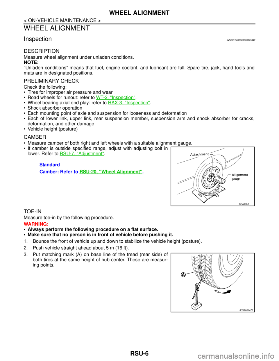
CAMBER
Measure camber of both right and left wheels with a suitable alignment gauge.
If camber is outside specified range, adjust with adjusting bolt in
lower. Refer to RSU-7, "
Adjustment".
TOE-IN
Measure toe-in by the following procedure.
WARNING:
Always perform the following procedure on a flat surface.
Make sure that no person is in front of vehicle before pushing it.
1. Bounce the front of vehicle up and down to stabilize the vehicle height (posture).
2. Push vehicle straight ahead about 5 m (16 ft).
3. Put matching mark (A) on base line of the tread (rear side) of
both tires at the same height of hub center. These are measur-
ing points.Standard
Camber: Refer to RSU-20, "
Wheel Alignment".
SRA096A
JPEIA0014ZZ
Page 5115 of 5121
FRONT WASHER NOZZLE AND TUBE
WW-103
< ON-VEHICLE REPAIR >
C
D
E
F
G
H
I
J
K
MA
B
WW
N
O
P
Check that air can pass through the hose by blowing forward (toward
the nozzle), and check that air cannot pass through by sucking.
ADJUSTMENT
Washer Nozzle Spray Position Adjustment
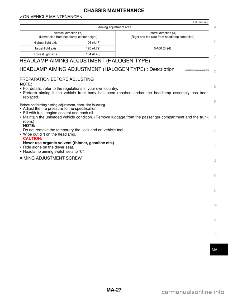
Adjust spray positions to match the positions shown in the figure.
Unit: mm (in)
JPLIA1139ZZ
1. End of cowl top cover
: Spray area
: Target spray position
Spray position H (Height) L (Width) Spray area
A 293.2 (11.54) 490.7 (19.32)φ 80 (3.15)
B 422.0 (16.61) 298.6 (11.76)φ 80 (3.15)
C 376.2 (14.81) 121.5 (4.78)φ 80 (3.15)
D 327.9 (12.91) 56.3 (2.22)φ 80 (3.15)
E 383.1 (15.08) 300 (11.81)φ 80 (3.15)
F 305.7 (12.04) 475.1 (18.70)φ 80 (3.15)
JPLIA1140ZZ
Page:
< prev 1-8 9-16 17-24