2008 NISSAN TEANA engine oil
[x] Cancel search: engine oilPage 4397 of 5121
POWER STEERING FLUID
ST-7
< ON-VEHICLE MAINTENANCE >
C
D
E
F
H
I
J
K
L
MA
B
ST
N
O
P
ON-VEHICLE MAINTENANCE
POWER STEERING FLUID
InspectionINFOID:0000000003826225
FLUID LEVEL
1. Check fluid level with engine stopped.
2. Ensure that fluid level is between MIN and MAX.
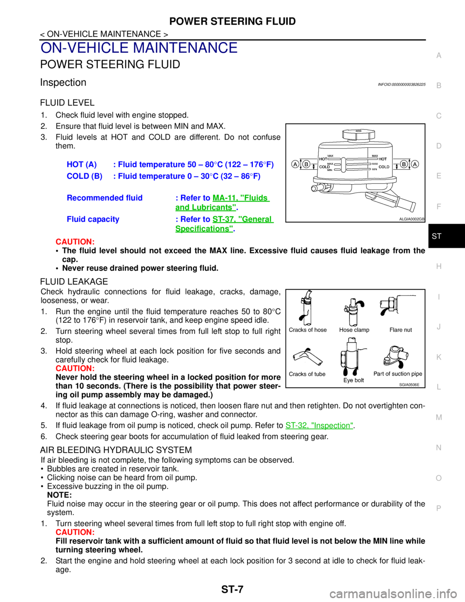
3. Fluid levels at HOT and COLD are different. Do not confuse
them.
CAUTION:
The fluid level should not exceed the MAX line. Excessive fluid causes fluid leakage from the
cap.
Never reuse drained power steering fluid.
FLUID LEAKAGE
Check hydraulic connections for fluid leakage, cracks, damage,
looseness, or wear.
1. Run the engine until the fluid temperature reaches 50 to 80°C
(122 to 176°F) in reservoir tank, and keep engine speed idle.
2. Turn steering wheel several times from full left stop to full right
stop.
3. Hold steering wheel at each lock position for five seconds and
carefully check for fluid leakage.
CAUTION:
Never hold the steering wheel in a locked position for more
than 10 seconds. (There is the possibility that power steer-
ing oil pump assembly may be damaged.)
4. If fluid leakage at connections is noticed, then loosen flare nut and then retighten. Do not overtighten con-
nector as this can damage O-ring, washer and connector.
5. If fluid leakage from oil pump is noticed, check oil pump. Refer to ST-32, "
Inspection".
6. Check steering gear boots for accumulation of fluid leaked from steering gear.
AIR BLEEDING HYDRAULIC SYSTEM
If air bleeding is not complete, the following symptoms can be observed.
Bubbles are created in reservoir tank.
Clicking noise can be heard from oil pump.
Excessive buzzing in the oil pump.
NOTE:
Fluid noise may occur in the steering gear or oil pump. This does not affect performance or durability of the
system.
1. Turn steering wheel several times from full left stop to full right stop with engine off.
CAUTION:
Fill reservoir tank with a sufficient amount of fluid so that fluid level is not below the MIN line while
turning steering wheel.
2. Start the engine and hold steering wheel at each lock position for 3 second at idle to check for fluid leak-
age.HOT (A) : Fluid temperature 50 – 80°C (122 – 176°F)
COLD (B) : Fluid temperature 0 – 30°C (32 – 86°F)
Recommended fluid : Refer to MA-11, "
Fluids
and Lubricants".
Fluid capacity : Refer to ST-37, "
General
Specifications".
ALGIA0002GB
SGIA0506E
Page 4398 of 5121

ST-8
< ON-VEHICLE MAINTENANCE >
POWER STEERING FLUID
3. Repeat step 2 above several times at approximately 3 second intervals.
CAUTION:
Never hold the steering wheel in a locked position for more than 10 seconds. (There is the possi-
bility that oil pump may be damaged.)
4. Check fluid for bubbles and white contamination.
5. Stop the engine if bubbles and white contamination do not drain out. Perform step 2 and 3 above after
waiting until bubbles and white contamination drain out.
6. Stop the engine, and then check fluid level.
Page 4400 of 5121
ST-10
< ON-VEHICLE MAINTENANCE >
STEERING WHEEL
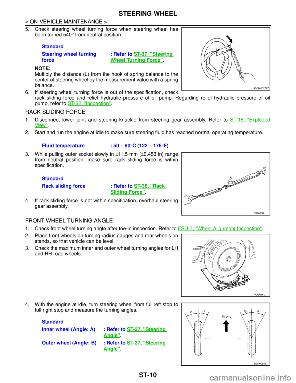
5. Check steering wheel turning force when steering wheel has
been turned 540° from neutral position.
NOTE:
Multiply the distance (L) from the hook of spring balance to the
center of steering wheel by the measurement value with a spring
balance.
6. If steering wheel turning force is out of the specification, check
rack sliding force and relief hydraulic pressure of oil pump. Regarding relief hydraulic pressure of oil
pump, refer to ST-32, "
Inspection".
RACK SLIDING FORCE
1. Disconnect lower joint and steering knuckle from steering gear assembly. Refer to ST-16, "Exploded
View".
2. Start and run the engine at idle to make sure steering fluid has reached normal operating temperature.
3. While pulling outer socket slowly in ±11.5 mm (±0.453 in) range
from neutral position, make sure rack sliding force is within
specification.
4. If rack sliding force is not within specification, overhaul steering
gear assembly.
FRONT WHEEL TURNING ANGLE
1. Check front wheel turning angle after toe-in inspection. Refer to FSU-7, "Wheel Alignment Inspection".
2. Place front wheels on turning radius gauges and rear wheels on
stands, so that vehicle can be level.
3. Check the maximum inner and outer wheel turning angles for LH
and RH road wheels.
4. With the engine at idle, turn steering wheel from full left stop to
full right stop and measure the turning angles.Standard
Steering wheel turning
force: Refer to ST-37, "
Steering
Wheel Turning Force".
JSGIA0027ZZ
Fluid temperature : 50 – 80°C (122 – 176°F)
Standard
Rack sliding force : Refer to ST-38, "
Rack
Sliding Force".
SST090B
FAA0016D
Standard
Inner wheel (Angle: A) : Refer to ST-37, "
Steering
Angle".
Outer wheel (Angle: B) : Refer to ST-37, "
Steering
Angle".
SGIA0055E
Page 4409 of 5121
STEERING GEAR AND LINKAGE
ST-19
< ON-VEHICLE REPAIR >
C
D
E
F
H
I
J
K
L
MA
B
ST
N
O
P
Removal and InstallationINFOID:0000000003806323
REMOVAL
1. Set the vehicle to the straight-ahead position.
2. Remove front tires.
3. Remove splash guards (RH and LH). Refer to EXT-22, "
FENDER PROTECTOR : Exploded View".
4. Remove engine under cover. Refer to EXT-28, "
Exploded View".
5. Remove heat insulator from front floor.
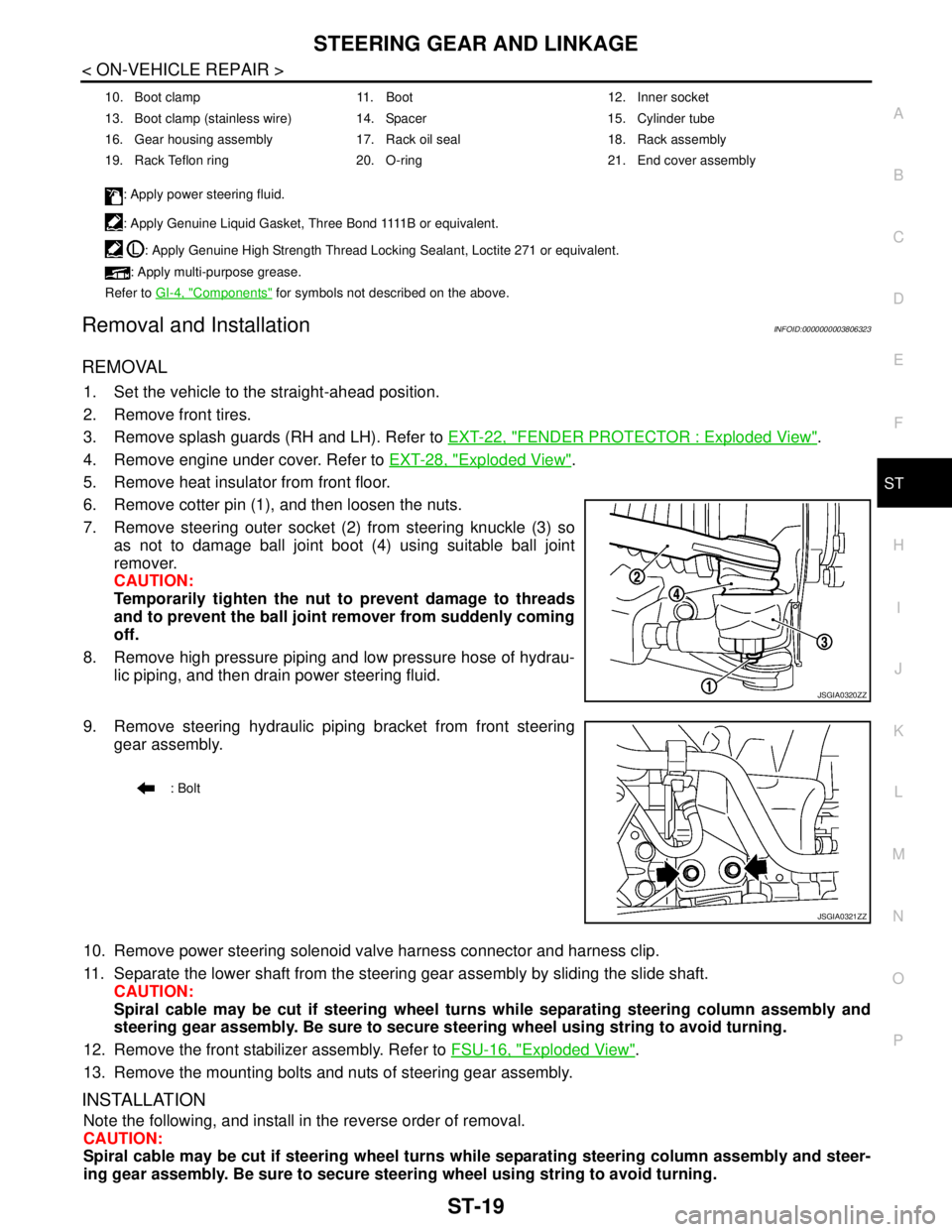
6. Remove cotter pin (1), and then loosen the nuts.
7. Remove steering outer socket (2) from steering knuckle (3) so
as not to damage ball joint boot (4) using suitable ball joint
remover.
CAUTION:
Temporarily tighten the nut to prevent damage to threads
and to prevent the ball joint remover from suddenly coming
off.
8. Remove high pressure piping and low pressure hose of hydrau-
lic piping, and then drain power steering fluid.
9. Remove steering hydraulic piping bracket from front steering
gear assembly.
10. Remove power steering solenoid valve harness connector and harness clip.
11. Separate the lower shaft from the steering gear assembly by sliding the slide shaft.
CAUTION:
Spiral cable may be cut if steering wheel turns while separating steering column assembly and
steering gear assembly. Be sure to secure steering wheel using string to avoid turning.
12. Remove the front stabilizer assembly. Refer to FSU-16, "
Exploded View".
13. Remove the mounting bolts and nuts of steering gear assembly.
INSTALLATION
Note the following, and install in the reverse order of removal.
CAUTION:
Spiral cable may be cut if steering wheel turns while separating steering column assembly and steer-
ing gear assembly. Be sure to secure steering wheel using string to avoid turning.
10. Boot clamp 11. Boot 12. Inner socket
13. Boot clamp (stainless wire) 14. Spacer 15. Cylinder tube
16. Gear housing assembly 17. Rack oil seal 18. Rack assembly
19. Rack Teflon ring 20. O-ring 21. End cover assembly
: Apply power steering fluid.
: A p p l y G e n u i n e L i q u i d G a s k e t , T h r e e B o n d 1111 B o r e q u i v a l e n t .
: Apply Genuine High Strength Thread Locking Sealant, Loctite 271 or equivalent.
: Apply multi-purpose grease.
Refer to GI-4, "
Components" for symbols not described on the above.
JSGIA0320ZZ
: Bolt
JSGIA0321ZZ
Page 4422 of 5121
ST-32
< ON-VEHICLE REPAIR >
POWER STEERING OIL PUMP
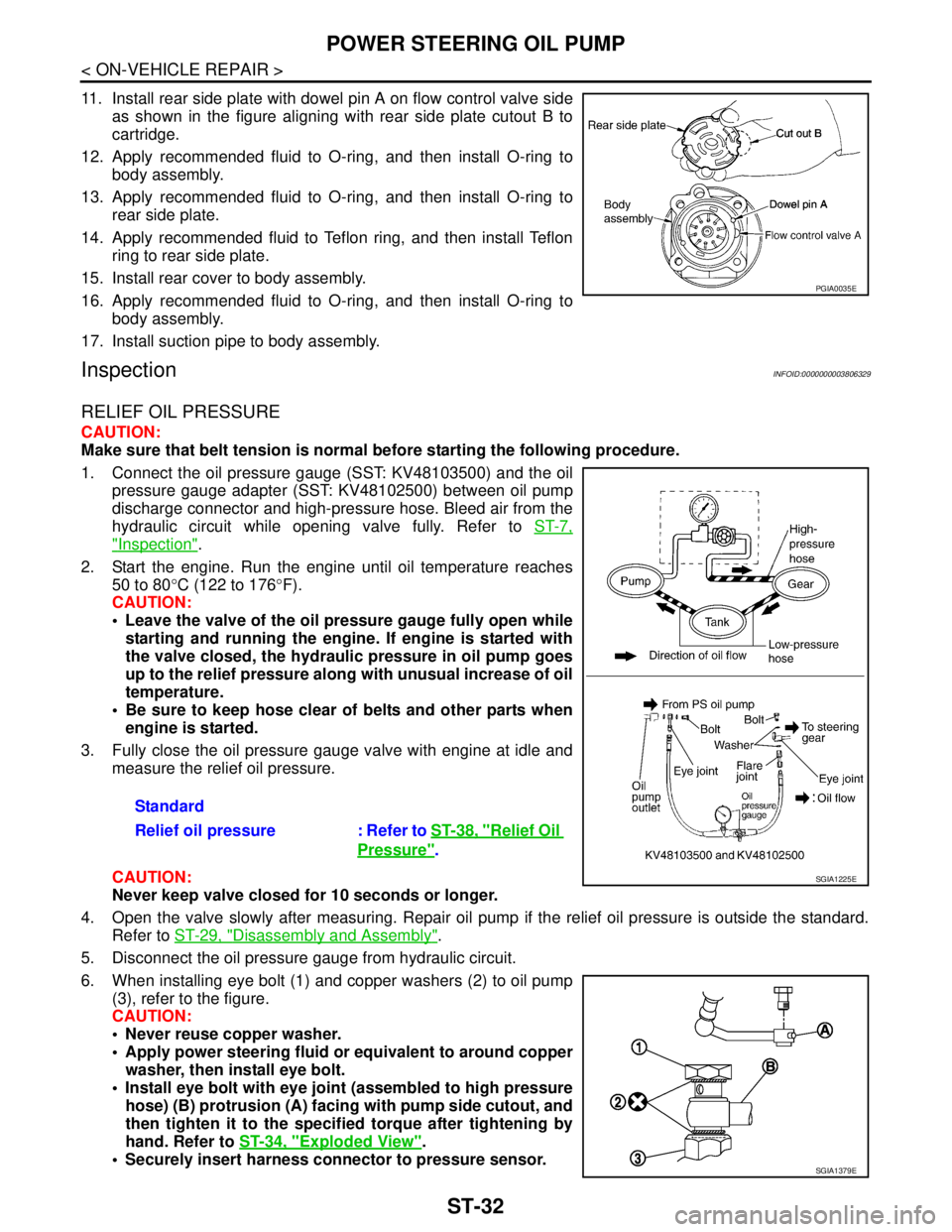
11. Install rear side plate with dowel pin A on flow control valve side
as shown in the figure aligning with rear side plate cutout B to
cartridge.
12. Apply recommended fluid to O-ring, and then install O-ring to
body assembly.
13. Apply recommended fluid to O-ring, and then install O-ring to
rear side plate.
14. Apply recommended fluid to Teflon ring, and then install Teflon
ring to rear side plate.
15. Install rear cover to body assembly.
16. Apply recommended fluid to O-ring, and then install O-ring to
body assembly.
17. Install suction pipe to body assembly.
InspectionINFOID:0000000003806329
RELIEF OIL PRESSURE
CAUTION:
Make sure that belt tension is normal before starting the following procedure.
1. Connect the oil pressure gauge (SST: KV48103500) and the oil
pressure gauge adapter (SST: KV48102500) between oil pump
discharge connector and high-pressure hose. Bleed air from the
hydraulic circuit while opening valve fully. Refer to ST-7,
"Inspection".
2. Start the engine. Run the engine until oil temperature reaches
50 to 80°C (122 to 176°F).
CAUTION:
Leave the valve of the oil pressure gauge fully open while
starting and running the engine. If engine is started with
the valve closed, the hydraulic pressure in oil pump goes
up to the relief pressure along with unusual increase of oil
temperature.
Be sure to keep hose clear of belts and other parts when
engine is started.
3. Fully close the oil pressure gauge valve with engine at idle and
measure the relief oil pressure.
CAUTION:
Never keep valve closed for 10 seconds or longer.
4. Open the valve slowly after measuring. Repair oil pump if the relief oil pressure is outside the standard.
Refer to ST-29, "
Disassembly and Assembly".
5. Disconnect the oil pressure gauge from hydraulic circuit.
6. When installing eye bolt (1) and copper washers (2) to oil pump
(3), refer to the figure.
CAUTION:
Never reuse copper washer.
Apply power steering fluid or equivalent to around copper
washer, then install eye bolt.
Install eye bolt with eye joint (assembled to high pressure
hose) (B) protrusion (A) facing with pump side cutout, and
then tighten it to the specified torque after tightening by
hand. Refer to ST-34, "
Exploded View".
Securely insert harness connector to pressure sensor.
PGIA0035E
Standard
Relief oil pressure : Refer to ST-38, "
Relief Oil
Pressure".
SGIA1225E
SGIA1379E
Page 4435 of 5121
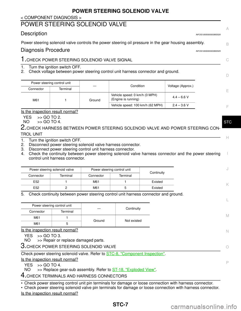
POWER STEERING SOLENOID VALVE
STC-7
< COMPONENT DIAGNOSIS >
C
D
E
F
H
I
J
K
L
MA
B
STC
N
O
P
POWER STEERING SOLENOID VALVE
DescriptionINFOID:0000000003893528
Power steering solenoid valve controls the power steering oil pressure in the gear housing assembly.
Diagnosis ProcedureINFOID:0000000003893529
1.CHECK POWER STEERING SOLENOID VALVE SIGNAL
1. Turn the ignition switch OFF.
2. Check voltage between power steering control unit harness connector and ground.
Is the inspection result normal?
YES >> GO TO 2.
NO >> GO TO 4.
2.CHECK HARNESS BETWEEN POWER STEERING SOLENOID VALVE AND POWER STEERING CON-
TROL UNIT
1. Turn the ignition switch OFF.
2. Disconnect power steering solenoid valve harness connector.
3. Disconnect power steering control unit harness connector.
4. Check the continuity between power steering solenoid valve harness connector and the power steering
control unit harness connector.
5. Check continuity between power steering control unit harness connector and ground.
Is the inspection result normal?
YES >> GO TO 3.
NO >> Repair or replace damaged parts.
3.CHECK POWER STEERING SOLENOID VALVE
Check power steering solenoid valve. Refer to STC-8, "
Component Inspection".
Is the inspection result normal?
YES >> GO TO 4.
NO >> Replace gear-sub assembly. Refer to ST-18, "
Exploded View".
4.CHECK TERMINALS AND HARNESS CONNECTORS
Check power steering control unit pin terminals for damage or loose connection with harness connector.
Check power steering solenoid valve pin terminals for damage or loose connection with harness connector.
Is the inspection result normal?
Power steering control unit
— Condition Voltage (Approx.)
Connector Terminal
M61 1 GroundVehicle speed: 0 km/h (0 MPH)
(Engine is running)4.4 – 6.6 V
Vehicle speed: 100 km/h (62 MPH) 2.4 – 3.6 V
Power steering solenoid valve Power steering control unit
Continuity
Connector Terminal Connector Terminal
E52 1 M61 1 Existed
E52 2 M61 5 Existed
Power steering control unit
—Continuity
Connector Terminal
M61 1
Ground Not existed
M61 5
Page 4477 of 5121

TM-4
ROAD TEST .....................................................148
Description .............................................................148
Check before Engine Is Started .............................148
Check at Idle ..........................................................149
Cruise Test ............................................................150
CVT POSITION ................................................152
Inspection and Adjustment ....................................152
ON-VEHICLE REPAIR ...............................153
TRANSMISSION CONTROL MODULE ..........153
Exploded View .......................................................153
Removal and Installation .......................................153
Adjustment .............................................................154
CONTROL DEVICE .........................................155
Exploded View .......................................................155
Removal and Installation .......................................155
Inspection and Adjustment ....................................156
CONTROL CABLE ..........................................157
Exploded View .......................................................157
Removal and Installation .......................................157
Inspection and Adjustment ....................................158
OIL PAN ...........................................................159
Exploded View .......................................................159
Removal and Installation .......................................159
Inspection ..............................................................160
SECONDARY SPEED SENSOR .....................161
Exploded View .......................................................161
Removal and Installation .......................................161
Inspection ..............................................................161
DIFFERENTIAL SIDE OIL SEAL ....................162
Exploded View .......................................................162
Removal and Installation .......................................162
Inspection ..............................................................163
AIR BREATHER HOSE ...................................164
Exploded View .......................................................164
Removal and Installation .......................................164
FLUID COOLER SYSTEM ...............................165
Exploded View .......................................................165
Removal and Installation .......................................165
Inspection ..............................................................167
REMOVAL AND INSTALLATION ..............168
TRANSAXLE ASSEMBLY ..............................168
Exploded View .......................................................168
Removal and Installation .......................................168
Inspection ..............................................................170
DISASSEMBLY AND ASSEMBLY ............172
TORQUE CONVERTER ..................................172
Exploded View .......................................................172
Disassembly ..........................................................172
Assembly ..............................................................172
Inspection ..............................................................173
SERVICE DATA AND SPECIFICATIONS
(SDS) .........................................................
174
SERVICE DATA AND SPECIFICATIONS
(SDS) ................................................................
174
General Specification ............................................174
Vehicle Speed When Shifting Gears .....................174
Stall Speed ............................................................174
Line Pressure ........................................................174
Solenoid Valves ....................................................175
CVT Fluid Temperature Sensor ............................175
Primary Speed Sensor ..........................................175
Secondary Speed Sensor .....................................175
Step Motor ............................................................175
Torque Converter ..................................................175
CVT: RE0F10A
BASIC INSPECTION .................................
176
DIAGNOSIS AND REPAIR WORK FLOW .......176
Work Flow .............................................................176
Diagnostic Work Sheet .........................................177
INSPECTION AND ADJUSTMENT ..................179
ADDITIONAL SERVICE WHEN REPLACING
CONTROL UNIT ......................................................
179
ADDITIONAL SERVICE WHEN REPLACING
CONTROL UNIT : Service After Replacing TCM
and Transaxle Assembly .......................................
179
FUNCTION DIAGNOSIS ...........................181
CVT SYSTEM ...................................................181
System Diagram ...................................................181
Component Parts Location ...................................182
MECHANICAL SYSTEM ..................................183
Cross-Sectional View ............................................183
System Diagram ...................................................184
System Description ...............................................184
Component Parts Location ...................................185
Component Description ........................................186
HYDRAULIC CONTROL SYSTEM ..................187
System Diagram ...................................................187
System Description ...............................................187
Component Parts Location ...................................188
Component Description ........................................189
CONTROL SYSTEM .........................................190
System Diagram ...................................................190
System Description ...............................................190
Component Parts Location ...................................192
Component Description ........................................193
LOCK-UP AND SELECT CONTROL SYSTEM
..
194
Page 4480 of 5121

TM-7
C
E
F
G
H
I
J
K
L
MA
B
TM
N
O
P Precaution for Supplemental Restraint System
(SRS) "AIR BAG" and "SEAT BELT PRE-TEN-
SIONER" ...............................................................
297
Precaution Necessary for Steering Wheel Rota-
tion after Battery Disconnect .................................
297
Precaution for Procedure without Cowl Top Cover ..298
Precaution for On Board Diagnosis (OBD) System
of CVT and Engine ................................................
298
Precaution for TCM and CVT Assembly Replace-
ment ......................................................................
298
Removal and Installation Procedure for CVT Unit
Connector ..............................................................
298
Precaution .............................................................299
Service Notice or Precaution .................................300
ATFTEMP COUNT Conversion Table ..................301
PREPARATION .........................................302
PREPARATION ................................................302
Special Service Tools ............................................302
Commercial Service Tools ....................................302
ON-VEHICLE MAINTENANCE ..................304
CVT FLUID .......................................................304
Inspection ..............................................................304
Changing ...............................................................305
STALL TEST ....................................................306
Inspection and Judgment ......................................306
LINE PRESSURE TEST ...................................308
Inspection and Judgment ......................................308
ROAD TEST .....................................................310
Description ............................................................310
Check before Engine Is Started ............................310
Check at Idle .........................................................311
Cruise Test ............................................................312
CVT POSITION .................................................314
Inspection and Adjustment ....................................314
ON-VEHICLE REPAIR ...............................315
TRANSMISSION CONTROL MODULE ...........315
Exploded View ......................................................315
Removal and Installation .......................................315
CONTROL DEVICE ..........................................317
Exploded View ......................................................317
Removal and Installation .......................................317
Inspection and Adjustment ....................................318
CONTROL CABLE ...........................................319
Exploded View ......................................................319
Removal and Installation .......................................319
Inspection and Adjustment ....................................320
OIL PAN ...........................................................321
Exploded View ......................................................321
Removal and Installation .......................................321
Inspection ..............................................................322
PRIMARY SPEED SENSOR ...........................323
Exploded View .......................................................323
Removal and Installation .......................................323
Inspection ..............................................................323
SECONDARY SPEED SENSOR ....................324
Exploded View .......................................................324
Removal and Installation .......................................324
Inspection ..............................................................324
DIFFERENTIAL SIDE OIL SEAL ....................325
Exploded View .......................................................325
Removal and Installation .......................................325
Inspection ..............................................................326
OIL PUMP FITTING BOLT ..............................327
Description .............................................................327
Exploded View .......................................................327
Removal and Installation .......................................327
Inspection ..............................................................327
AIR BREATHER HOSE ..................................328
Exploded View .......................................................328
Removal and Installation .......................................328
FLUID COOLER SYSTEM ..............................329
Exploded View .......................................................329
Removal and Installation .......................................329
Inspection ..............................................................331
REMOVAL AND INSTALLATION .............332
TRANSAXLE ASSEMBLY ..............................332
Exploded View .......................................................332
Removal and Installation .......................................332
Inspection ..............................................................334
DISASSEMBLY AND ASSEMBLY ............335
TORQUE CONVERTER AND CONVERTER
HOUSING OIL SEAL ......................................
335
Exploded View .......................................................335
Disassembly ..........................................................335
Assembly ...............................................................335
Inspection ..............................................................336
SERVICE DATA AND SPECIFICATIONS
(SDS) ..........................................................
337
SERVICE DATA AND SPECIFICATIONS
(SDS) ...............................................................
337
General Specification ............................................337
Vehicle Speed When Shifting Gears .....................337
Stall Speed ............................................................337
Line Pressure ........................................................337
Solenoid Valves .....................................................338
CVT Fluid Temperature Sensor .............................338
Primary Speed Sensor ..........................................338
Secondary Speed Sensor ......................................338