2008 NISSAN TEANA heating
[x] Cancel search: heatingPage 1171 of 5121

DRIVER SIDE DOOR MIRROR DEFOGGER
DEF-21
< COMPONENT DIAGNOSIS >
C
D
E
F
G
H
I
J
K
MA
B
DEF
N
O
P
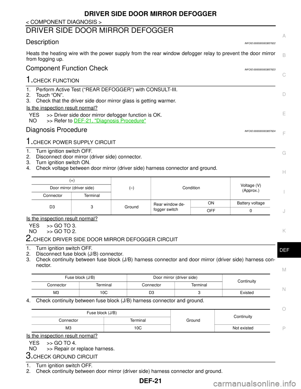
DRIVER SIDE DOOR MIRROR DEFOGGER
DescriptionINFOID:0000000003857622
Heats the heating wire with the power supply from the rear window defogger relay to prevent the door mirror
from fogging up.
Component Function CheckINFOID:0000000003857623
1.CHECK FUNCTION
1. Perform Active Test (“REAR DEFOGGER”) with CONSULT-III.
2. Touch “ON”.
3. Check that the driver side door mirror glass is getting warmer.
Is the inspection result normal?
YES >> Driver side door mirror defogger function is OK.
NO >> Refer to DEF-21, "
Diagnosis Procedure"
Diagnosis ProcedureINFOID:0000000003857624
1.CHECK POWER SUPPLY CIRCUIT
1. Turn ignition switch OFF.
2. Disconnect door mirror (driver side) connector.
3. Turn ignition switch ON.
4. Check voltage between door mirror (driver side) harness connector and ground.
Is the inspection result normal?
YES >> GO TO 3.
NO >> GO TO 2.
2.CHECK DRIVER SIDE DOOR MIRROR DEFOGGER CIRCUIT
1. Turn ignition switch OFF.
2. Disconnect fuse block (J/B) connector.
3. Check continuity between fuse block (J/B) harness connector and door mirror (driver side) harness con-
nector.
4. Check continuity between fuse block (J/B) harness connector and ground.
Is the inspection result normal?
YES >> GO TO 4.
NO >> Repair or replace harness.
3.CHECK GROUND CIRCUIT
1. Turn ignition switch OFF.
2. Check continuity between door mirror (driver side) harness connector and ground.
(+)
(–) Condition Voltage (V)
(Approx.) Door mirror (driver side)
Connector Terminal
D3 3 GroundRear window de-
fogger switchON Battery voltage
OFF 0
Fuse block (J/B) Door mirror (driver side)
Continuity
Connector Terminal Connector Terminal
M3 10C D3 3 Existed
Fuse block (J/B)
GroundContinuity
Connector Terminal
M3 10C Not existed
Page 1173 of 5121

PASSENGER SIDE DOOR MIRROR DEFOGGER
DEF-23
< COMPONENT DIAGNOSIS >
C
D
E
F
G
H
I
J
K
MA
B
DEF
N
O
P
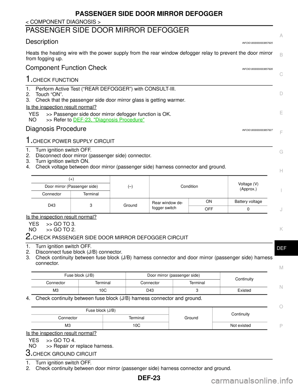
PASSENGER SIDE DOOR MIRROR DEFOGGER
DescriptionINFOID:0000000003857625
Heats the heating wire with the power supply from the rear window defogger relay to prevent the door mirror
from fogging up.
Component Function CheckINFOID:0000000003857626
1.CHECK FUNCTION
1. Perform Active Test (“REAR DEFOGGER”) with CONSULT-III.
2. Touch “ON”.
3. Check that the passenger side door mirror glass is getting warmer.
Is the inspection result normal?
YES >> Passenger side door mirror defogger function is OK.
NO >> Refer to DEF-23, "
Diagnosis Procedure"
Diagnosis ProcedureINFOID:0000000003857627
1.CHECK POWER SUPPLY CIRCUIT
1. Turn ignition switch OFF.
2. Disconnect door mirror (passenger side) connector.
3. Turn ignition switch ON.
4. Check voltage between door mirror (passenger side) harness connector and ground.
Is the inspection result normal?
YES >> GO TO 3.
NO >> GO TO 2.
2.CHECK PASSENGER SIDE DOOR MIRROR DEFOGGER CIRCUIT
1. Turn ignition switch OFF.
2. Disconnect fuse block (J/B) connector.
3. Check continuity between fuse block (J/B) harness connector and door mirror (passenger side) harness
connector.
4. Check continuity between fuse block (J/B) harness connector and ground.
Is the inspection result normal?
YES >> GO TO 4.
NO >> Repair or replace harness.
3.CHECK GROUND CIRCUIT
1. Turn ignition switch OFF.
2. Check continuity between door mirror (passenger side) harness connector and ground.
(+)
(–) ConditionVoltage (V)
(Approx.) Door mirror (Passenger side)
Connector Terminal
D43 3 GroundRear window de-
fogger switchON Battery voltage
OFF 0
Fuse block (J/B) Door mirror (passenger side)
Continuity
Connector Terminal Connector Terminal
M3 10C D43 3 Existed
Fuse block (J/B)
GroundContinuity
Connector Terminal
M3 10C Not existed
Page 1670 of 5121
![NISSAN TEANA 2008 Service Manual P0300, P0301, P0302, P0303, P0304, P0305, P0306 MISFIRE
EC-209
< COMPONENT DIAGNOSIS >[VQ25DE, VQ35DE]
C
D
E
F
G
H
I
J
K
L
MA
EC
N
P O
P0300, P0301, P0302, P0303, P0304, P0305, P0306 MISFIRE
DTC Logic NISSAN TEANA 2008 Service Manual P0300, P0301, P0302, P0303, P0304, P0305, P0306 MISFIRE
EC-209
< COMPONENT DIAGNOSIS >[VQ25DE, VQ35DE]
C
D
E
F
G
H
I
J
K
L
MA
EC
N
P O
P0300, P0301, P0302, P0303, P0304, P0305, P0306 MISFIRE
DTC Logic](/manual-img/5/57391/w960_57391-1669.png)
P0300, P0301, P0302, P0303, P0304, P0305, P0306 MISFIRE
EC-209
< COMPONENT DIAGNOSIS >[VQ25DE, VQ35DE]
C
D
E
F
G
H
I
J
K
L
MA
EC
N
P O
P0300, P0301, P0302, P0303, P0304, P0305, P0306 MISFIRE
DTC LogicINFOID:0000000003856617
DTC DETECTION LOGIC
When a misfire occurs, engine speed will fluctuate. If the engine speed fluctuates enough to cause the crank-
shaft position (CKP) sensor (POS) signal to vary, ECM can determine that a misfire is occurring.
The misfire detection logic consists of the following two conditions.
1. One Trip Detection Logic (Three Way Catalyst Damage)
On the 1st trip that a misfire condition occurs that can damage the three way catalyst (TWC) due to over-
heating, the MI will blink.
When a misfire condition occurs, the ECM monitors the CKP sensor signal every 200 engine revolutions
for a change.
When the misfire condition decreases to a level that will not damage the TWC, the MI will turn off.
If another misfire condition occurs that can damage the TWC on a second trip, the MI will blink.
When the misfire condition decreases to a level that will not damage the TWC, the MI will remain on.
If another misfire condition occurs that can damage the TWC, the MI will begin to blink again.
2. Two Trip Detection Logic (Exhaust quality deterioration)
For misfire conditions that will not damage the TWC (but will affect vehicle emissions), the MI will only light
when the misfire is detected on a second trip. During this condition, the ECM monitors the CKP sensor
signal every 1,000 engine revolutions.
A misfire malfunction can be detected in any one cylinder or in multiple cylinders.
DTC CONFIRMATION PROCEDURE
1.PRECONDITIONING
If DTC Confirmation Procedure has been previously conducted, always turn ignition switch OFF and wait at
least 10 seconds before conducting the next test.
>> GO TO 2.
2.PERFORM DTC CONFIRMATION PROCEDURE-I
1. Start engine and warm it up to normal operating temperature.
2. Turn ignition switch OFF and wait at least 10 seconds.
3. Restart engine and let it idle for about 15 minutes.
4. Check 1st trip DTC.
Is 1st trip DTC detected?
YES >> Go to EC-210, "Diagnosis Procedure".
NO >> GO TO 3.
3.PERFORM DTC CONFIRMATION PROCEDURE-II
1. Turn ignition switch OFF and wait at least 10 seconds.
Sensor Input signal to ECM ECM function
Crankshaft position sensor (POS) Engine speed On board diagnosis of misfire
DTC No. Trouble diagnosis name DTC detecting condition Possible cause
P0300 Multiple cylinder misfires detected Multiple cylinder misfire. Improper spark plug
Insufficient compression
Incorrect fuel pressure
The fuel injector circuit is open or shorted
Fuel injector
Intake air leak
The ignition signal circuit is open or shorted
Lack of fuel
Signal plate
A/F sensor 1
Incorrect PCV hose connection P0301 No.1 cylinder misfire detected No. 1 cylinder misfires.
P0302 No. 2 cylinder misfire detected No. 2 cylinder misfires.
P0303 No. 3 cylinder misfire detected No. 3 cylinder misfires.
P0304 No. 4 cylinder misfire detected No. 4 cylinder misfires.
P0305 No. 5 cylinder misfire detected No. 5 cylinder misfires.
P0306 No. 6 cylinder misfire detected No. 6 cylinder misfires.
Page 1882 of 5121

PRECAUTIONS
EM-7
< PRECAUTION >
C
D
E
F
G
H
I
J
K
L
MA
EM
N
P O
Ensure thread and seat surfaces are clean and coated with engine oil.
Precaution for Liquid GasketINFOID:0000000003802233
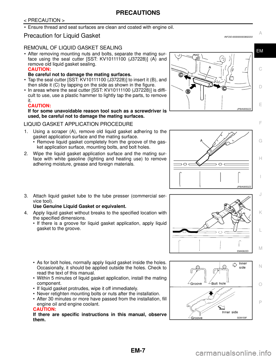
REMOVAL OF LIQUID GASKET SEALING
After removing mounting nuts and bolts, separate the mating sur-
f a c e u s i n g t h e s e a l c u t t e r [ S S T: K V 1 0 1111 0 0 ( J37228)] (A) and
remove old liquid gasket sealing.
CAUTION:
Be careful not to damage the mating surfaces.
Tap the seal cutter [SST: KV10111100 (J37228)] to insert it (B), and
then slide it (C) by tapping on the side as shown in the figure.
In areas where the seal cutter [SST: KV10111100 (J37228)] is diffi-
cult to use, use a plastic hammer to lightly tap the parts, to remove
it.
CAUTION:
If for some unavoidable reason tool such as a screwdriver is
used, be careful not to damage the mating surfaces.
LIQUID GASKET APPLICATION PROCEDURE
1. Using a scraper (A), remove old liquid gasket adhering to the
gasket application surface and the mating surface.
Remove liquid gasket completely from the groove of the gas-
ket application surface, mounting bolts, and bolt holes.
2. Wipe the liquid gasket application surface and the mating sur-
face with white gasoline (lighting and heating use) to remove
adhering moisture, grease and foreign materials.
3. Attach liquid gasket tube to the tube presser (commercial ser-
vice tool).
Use Genuine Liquid Gasket or equivalent.
4. Apply liquid gasket without breaks to the specified location with
the specified dimensions.
If there is a groove for liquid gasket application, apply liquid
gasket to the groove.
As for bolt holes, normally apply liquid gasket inside the holes.
Occasionally, it should be applied outside the holes. Check to
read the text of this manual.
Within 5 minutes of liquid gasket application, install the mating
component.
If liquid gasket protrudes, wipe it off immediately.
Never retighten mounting bolts or nuts after the installation.
After 30 minutes or more have passed from the installation, fill
engine oil and engine coolant.
CAUTION:
If there are specific instructions in this manual, observe
them.
JPBIA0052ZZ
JPBIA0053ZZ
EMA0622D
SEM159F
Page 2529 of 5121

GI-36
< BASIC INSPECTION >
SERVICE INFORMATION FOR ELECTRICAL INCIDENT
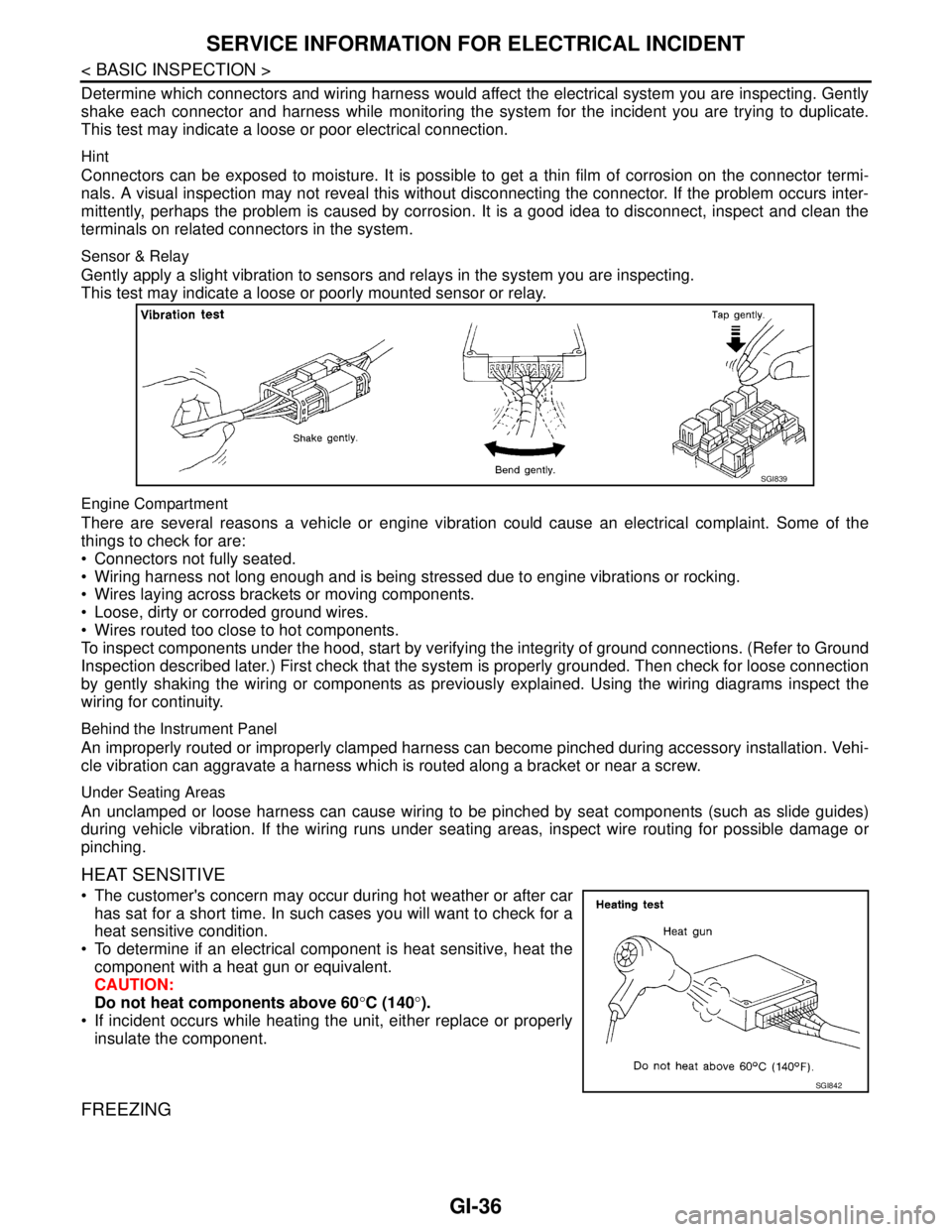
Determine which connectors and wiring harness would affect the electrical system you are inspecting. Gently
shake each connector and harness while monitoring the system for the incident you are trying to duplicate.
This test may indicate a loose or poor electrical connection.
Hint
Connectors can be exposed to moisture. It is possible to get a thin film of corrosion on the connector termi-
nals. A visual inspection may not reveal this without disconnecting the connector. If the problem occurs inter-
mittently, perhaps the problem is caused by corrosion. It is a good idea to disconnect, inspect and clean the
terminals on related connectors in the system.
Sensor & Relay
Gently apply a slight vibration to sensors and relays in the system you are inspecting.
This test may indicate a loose or poorly mounted sensor or relay.
Engine Compartment
There are several reasons a vehicle or engine vibration could cause an electrical complaint. Some of the
things to check for are:
Connectors not fully seated.
Wiring harness not long enough and is being stressed due to engine vibrations or rocking.
Wires laying across brackets or moving components.
Loose, dirty or corroded ground wires.
Wires routed too close to hot components.
To inspect components under the hood, start by verifying the integrity of ground connections. (Refer to Ground
Inspection described later.) First check that the system is properly grounded. Then check for loose connection
by gently shaking the wiring or components as previously explained. Using the wiring diagrams inspect the
wiring for continuity.
Behind the Instrument Panel
An improperly routed or improperly clamped harness can become pinched during accessory installation. Vehi-
cle vibration can aggravate a harness which is routed along a bracket or near a screw.
Under Seating Areas
An unclamped or loose harness can cause wiring to be pinched by seat components (such as slide guides)
during vehicle vibration. If the wiring runs under seating areas, inspect wire routing for possible damage or
pinching.
HEAT SENSITIVE
The customer's concern may occur during hot weather or after car
has sat for a short time. In such cases you will want to check for a
heat sensitive condition.
To determine if an electrical component is heat sensitive, heat the
component with a heat gun or equivalent.
CAUTION:
Do not heat components above 60°C (140°).
If incident occurs while heating the unit, either replace or properly
insulate the component.
FREEZING
SGI839
SGI842
Page 2630 of 5121

HAC-2
DTC Logic ...............................................................53
Diagnosis Procedure ..............................................54
Component Inspection ............................................55
B2632, B2633 AIR MIX DOOR MOTOR
(DRIVER SIDE) ..................................................
56
Description ..............................................................56
DTC Logic ...............................................................56
Diagnosis Procedure ..............................................57
B2634, B2635 AIR MIX DOOR MOTOR (PAS-
SENGER SIDE) ..................................................
58
Description ..............................................................58
DTC Logic ...............................................................58
Diagnosis Procedure ..............................................59
B2636, B2637, B2638, B2639, B2654, B2655
MODE DOOR MOTOR ......................................
60
Description ..............................................................60
DTC Logic ...............................................................60
Diagnosis Procedure ..............................................61
B263D B263E, B263F, B2656 INTAKE DOOR
MOTOR ..............................................................
63
Description ..............................................................63
DTC Logic ...............................................................63
Diagnosis Procedure ..............................................64
POWER SUPPLY AND GROUND CIRCUIT .....65
A/C AUTO AMP. .......................................................65
A/C AUTO AMP. : Diagnosis Procedure ................65
A/C CONTROL ..........................................................65
A/C CONTROL : Diagnosis Procedure ...................65
A/C DISPLAY ............................................................66
A/C DISPLAY : Diagnosis Procedure .....................66
A/C AUTO AMP. ................................................67
Description ..............................................................67
Component Function Check ...................................67
Diagnosis Procedure ..............................................67
BLOWER MOTOR .............................................68
Description ..............................................................68
Component Function Check .................................68
Diagnosis Procedure ..............................................68
Component Inspection ............................................71
MAGNET CLUTCH ............................................72
Description ..............................................................72
Component Function Check ...................................72
Diagnosis Procedure ..............................................72
A/C CONTROL SIGNAL CIRCUIT ....................74
Diagnosis Procedure ..............................................74
ECU DIAGNOSIS ........................................75
A/C AUTO AMP. ................................................75
Reference Value .....................................................75
Wiring Diagram - AIR CONDITIONER CONTROL
SYSTEM - ...............................................................
77
Fail-Safe ..................................................................84
DTC Inspection Priority Chart ...............................85
DTC Index ...............................................................85
SYMPTOM DIAGNOSIS ............................87
AIR CONDITIONER CONTROL ........................87
Diagnosis Chart By Symptom .................................87
INSUFFICIENT COOLING .................................88
Description ..............................................................88
Inspection procedure ..............................................88
INSUFFICIENT HEATING .................................91
Description ..............................................................91
Inspection procedure ..............................................91
NOISE ................................................................94
Description ..............................................................94
Inspection procedure ..............................................94
MEMORY FUNCTION DOES NOT OPERATE ...96
Description ..............................................................96
Inspection procedure ..............................................96
PRECAUTION ............................................97
PRECAUTIONS .................................................97
Precaution for Supplemental Restraint System
(SRS) "AIR BAG" and "SEAT BELT PRE-TEN-
SIONER" .................................................................
97
Precaution Necessary for Steering Wheel Rota-
tion after Battery Disconnect ...................................
97
Precaution for Procedure without Cowl Top Cover ...98
Precautions For Xenon Headlamp Service .............98
Working with HFC-134a (R-134a) ...........................98
General Refrigerant Precaution ..............................99
Refrigerant Connection ...........................................99
Service Equipment ................................................101
COMPRESSOR ................................................104
General Precautions .............................................104
FLUORESCENT LEAK DETECTOR ................105
General Precautions .............................................105
WITH 7 INCH DISPLAY
BASIC INSPECTION .................................
106
DIAGNOSIS AND REPAIR WORKFLOW ........106
Work Flow .............................................................106
INSPECTION AND ADJUSTMENT ..................108
WITHOUT INTELLIGENT AIR CONDITIONER
SYSTEM ..................................................................
108
WITHOUT INTELLIGENT AIR CONDITIONER
SYSTEM : Description & Inspection .....................
108
WITHOUT INTELLIGENT AIR CONDITIONER
SYSTEM : Temperature Setting Trimmer .............
110
Page 2633 of 5121

HAC-5
C
D
E
F
G
H
J
K
L
MA
B
HAC
N
O
P WITH INTELLIGENT AIR CONDITIONER SYS-
TEM : Wiring Diagram - AIR CONDITIONER
CONTROL SYSTEM - ...........................................
215
WITH INTELLIGENT AIR CONDITIONER SYS-
TEM : Fail-Safe .....................................................
223
WITH INTELLIGENT AIR CONDITIONER SYS-
TEM : DTC Inspection Priority Chart ..................
224
WITH INTELLIGENT AIR CONDITIONER SYS-
TEM : DTC Index ..................................................
224
SYMPTOM DIAGNOSIS ............................226
AIR CONDITIONER CONTROL .......................226
Diagnosis Chart By Symptom ...............................226
PLASMACLUSTER SYSTEM DOES NOT OP-
ERATE ..............................................................
227
WITH INTELLIGENT AIR CONDITIONER SYS-
TEM ..........................................................................
227
WITH INTELLIGENT AIR CONDITIONER SYS-
TEM : Description ..................................................
227
WITH INTELLIGENT AIR CONDITIONER SYS-
TEM : Inspection procedure ..................................
227
INSUFFICIENT COOLING ...............................228
Description ............................................................228
Inspection procedure .............................................228
INSUFFICIENT HEATING ................................231
Description ............................................................231
Inspection procedure .............................................231
NOISE ..............................................................234
Description .............................................................234
Inspection procedure .............................................234
MEMORY FUNCTION DOES NOT OPERATE .236
Description .............................................................236
Inspection procedure .............................................236
PRECAUTION ............................................237
PRECAUTIONS ...............................................237
Precaution for Supplemental Restraint System
(SRS) "AIR BAG" and "SEAT BELT PRE-TEN-
SIONER" ...............................................................
237
Precaution Necessary for Steering Wheel Rota-
tion after Battery Disconnect .................................
237
Precaution for Procedure without Cowl Top Cover ..238
Precautions For Xenon Headlamp Service ...........238
Working with HFC-134a (R-134a) .........................238
General Refrigerant Precaution .............................239
Refrigerant Connection ..........................................239
Service Equipment ................................................241
COMPRESSOR ...............................................244
General Precautions ..............................................244
FLUORESCENT LEAK DETECTOR ..............245
General Precautions ..............................................245
Page 2637 of 5121
![NISSAN TEANA 2008 Service Manual INSPECTION AND ADJUSTMENT
HAC-9
< BASIC INSPECTION >[WITHOUT 7 INCH DISPLAY]
C
D
E
F
G
H
J
K
L
MA
B
HAC
N
O
P
4.CHECK INTAKE AIR
1. Press the REC switch. REC indicator is turned ON.
2. Press the FRE s NISSAN TEANA 2008 Service Manual INSPECTION AND ADJUSTMENT
HAC-9
< BASIC INSPECTION >[WITHOUT 7 INCH DISPLAY]
C
D
E
F
G
H
J
K
L
MA
B
HAC
N
O
P
4.CHECK INTAKE AIR
1. Press the REC switch. REC indicator is turned ON.
2. Press the FRE s](/manual-img/5/57391/w960_57391-2636.png)
INSPECTION AND ADJUSTMENT
HAC-9
< BASIC INSPECTION >[WITHOUT 7 INCH DISPLAY]
C
D
E
F
G
H
J
K
L
MA
B
HAC
N
O
P
4.CHECK INTAKE AIR
1. Press the REC switch. REC indicator is turned ON.
2. Press the FRE switch. FRE indicator is turned ON.
3. Listen for the intake door position change. (Slight change of blower sound can be heard.)
NOTE:
Confirm that the compressor clutch is engaged (sound or visual inspection) and the intake door position is at
the FRE when the DEF is selected.
Is the inspection result normal?
YES >> GO TO 5.
NO >> Intake door system malfunction: HAC-64, "
Diagnosis Procedure".
5.CHECK A/C SWITCH
1. Press the A/C switch.
2. The A/C switch indicator is turned ON.
Confirm that the compressor clutch engages (sound or visual inspection).
Is the inspection result normal?
YES >> GO TO 6.
NO >> Magnet clutch system malfunction: HAC-72, "
Diagnosis Procedure".
6.CHECK WITH TEMPERATURE SETTING LOWERED
1. Operate the compressor.
2. Operate the temperature control switch (driver side) and lower the temperature setting to 18°C (60°F).
3. Check that the cool air blows from the outlets.
Is the inspection result normal?
YES >> GO TO 7.
NO >> Insufficient cooling: HAC-88, "
Inspection procedure".
7.CHECK WITH TEMPERATURE SETTING RAISED
1. Operate the temperature control switch (driver side) and raise the temperature setting to 32°C (90°F) after
warming up the engine.
2. Check that the warm air blows from the outlets.
Is the inspection result normal?
YES >> GO TO 8.
NO >> Insufficient heating: HAC-91, "
Inspection procedure".
8.CHECK LEFT AND RIGHT VENTILATION TEMPERATURE SEPARATELY CONTROL SYSTEM FUNC-
TION
1. Press the DUAL switch, and then check that “DUAL” is shown on the display.
2. Operate the temperature control switch (driver side). Check that the discharge air temperature (driver
side) changes.
3. Operate the temperature control switch (passenger side). Check that the discharge air temperature (pas-
senger side) changes.
4. Press the DUAL switch, and then check that the temperature setting (LH/RH) is unified to the driver side
temperature setting.
Is the inspection result normal?
YES >> GO TO 9.
NO >> Refer to HAC-87, "
Diagnosis Chart By Symptom" and perform the appropriate diagnosis.
9.CHECK AUTO MODE
1. Press the AUTO switch, and then check that “AUTO” is shown on the display.
2. Operate the temperature control switch (driver side). Check that the fan speed or outlet changes (the dis-
charge air temperature or fan speed varies depending on the ambient temperature, in-vehicle tempera-
ture, and temperature setting).
Is the inspection result normal?
YES >> GO TO 10.
NO >> Refer to HAC-87, "
Diagnosis Chart By Symptom" and perform the appropriate diagnosis.