2008 NISSAN TEANA Ccu
[x] Cancel search: CcuPage 1087 of 5121
![NISSAN TEANA 2008 Service Manual BRC-146
< SYMPTOM DIAGNOSIS >[VDC/TCS/ABS]
PEDAL VIBRATION OR ABS OPERATION SOUND OCCURS
PEDAL VIBRATION OR ABS OPERATION SOUND OCCURS
Diagnosis ProcedureINFOID:0000000003767027
CAUTION:
Under the fol NISSAN TEANA 2008 Service Manual BRC-146
< SYMPTOM DIAGNOSIS >[VDC/TCS/ABS]
PEDAL VIBRATION OR ABS OPERATION SOUND OCCURS
PEDAL VIBRATION OR ABS OPERATION SOUND OCCURS
Diagnosis ProcedureINFOID:0000000003767027
CAUTION:
Under the fol](/manual-img/5/57391/w960_57391-1086.png)
BRC-146
< SYMPTOM DIAGNOSIS >[VDC/TCS/ABS]
PEDAL VIBRATION OR ABS OPERATION SOUND OCCURS
PEDAL VIBRATION OR ABS OPERATION SOUND OCCURS
Diagnosis ProcedureINFOID:0000000003767027
CAUTION:
Under the following conditions, ABS is activated and vibration is felt when brake pedal is lightly
depressed (just place a foot on it). However, this is normal.
When shifting gears
When driving on slippery road
During cornering at high speed
When passing over bumps or grooves [at approximately 50 mm (1.97 in) or more]
When pulling away just after starting engine [at approximately 10 km/h (6 MPH) or higher]
1.SYMPTOM CHECK 1
Check that there are pedal vibrations when the engine is started.
Do vibrations occur?
YES >> GO TO 2.
NO >> Inspect the brake pedal.
2.SYMPTOM CHECK 2
Check that there are ABS operation noises when the engine is started.
Do the operation noises occur?
YES >> GO TO 3.
NO >> Perform self-diagnosis.
3.SYMPTOM CHECK 3
Check symptoms when electrical component (headlamps, etc.) switches are operated.
Do symptoms occur?
YES >> Check if there is a radio, antenna, antenna lead wire, or wiring close to the control unit. If there is,
move it farther away.
NO >> Normal
Page 1089 of 5121
![NISSAN TEANA 2008 Service Manual BRC-148
< SYMPTOM DIAGNOSIS >[VDC/TCS/ABS]
NORMAL OPERATING CONDITION
NORMAL OPERATING CONDITION
DescriptionINFOID:0000000003767029
Symptom Result
Slight vibrations are felt on the brake pedal and the NISSAN TEANA 2008 Service Manual BRC-148
< SYMPTOM DIAGNOSIS >[VDC/TCS/ABS]
NORMAL OPERATING CONDITION
NORMAL OPERATING CONDITION
DescriptionINFOID:0000000003767029
Symptom Result
Slight vibrations are felt on the brake pedal and the](/manual-img/5/57391/w960_57391-1088.png)
BRC-148
< SYMPTOM DIAGNOSIS >[VDC/TCS/ABS]
NORMAL OPERATING CONDITION
NORMAL OPERATING CONDITION
DescriptionINFOID:0000000003767029
Symptom Result
Slight vibrations are felt on the brake pedal and the operation noises occur, when VDC, TCS or ABS is acti-
vated.
This is a normal condi-
tion due to the VDC,
TCS or ABS activation. Stopping distance is longer than that of vehicles without ABS when the vehicle drives on rough, gravel, or
snow-covered (fresh, deep snow) roads.
The brake pedal moves and generates noises, when TCS or VDC is activated due to rapid acceleration or
sharp turn.
The brake pedal vibrates and motor operation noises occur from the engine room, after the engine starts and
just after the vehicle starts.This is a normal, and it is
caused by the ABS op-
eration check.
Depending on the road conditions, the driver may experience a sluggish feel. This is normal, because
TCS places the highest
priority on the optimum
traction (stability). TCS may activate momentarily if wheel speed changes when driving over location where friction coefficient
varies, when downshifting, or when fully depressing accelerator pedal.
The ABS warning lamp, VDC OFF indicator lamp and SLIP indicator lamp may turn ON when the vehicle is
subject to strong shaking or large vibration, such as when the vehicle is rotating on a turntable or located on
a ship while the engine is running. In this case, restart the
engine on a normal
road. If the normal con-
dition is restored, there
is no malfunction. At
that time, erase the self-
diagnosis memory. VDC may not operate normally or the ABS warning lamp, VDC OFF indicator lamp, and SLIP indicator lamp
may illuminate, when running on a special road that is extremely slanted (e.g. bank in a circuit course).
A malfunction may occur in the yaw rate/side G sensor system, when the vehicle turns sharply, such as dur-
ing a spin turn, axle turn, or drift driving, while the VDC function is off (VDC OFF indicator lamp illuminated).
The vehicle speed will not increase even though the accelerator pedal is depressed, when inspecting the
speedometer on a 2-wheel chassis dynamometer. Normal (Deactivate the
VDC/TCS function be-
fore performing an in-
spection on a chassis
dynamometer.)
VDC OFF indicator lamp and SLIP indicator lamp may simultaneously turn on when low tire pressure warn-
ing lamp turns on.This is not a VDC sys-
tem error but results
from characteristic
change of tire.
Page 1104 of 5121

CHG-6
< FUNCTION DIAGNOSIS >
CHARGING SYSTEM
Component part Description
AlternatorThe alternator provides DC voltage to operate the vehicle's electri-
cal system and to keep the battery charged.
Combination meter (Charge warning lamp)The IC voltage regulator warning function activates to illuminate
the charge warning lamp, if any of the following symptoms occur
while alternator is operating:
Excessive voltage is produced.
No voltage is produced.
Page 1128 of 5121
PRECAUTIONS
CO-5
< PRECAUTION >
C
D
E
F
G
H
I
J
K
L
MA
CO
N
P O
PRECAUTION
PRECAUTIONS
Precaution for Supplemental Restraint System (SRS) "AIR BAG" and "SEAT BELT
PRE-TENSIONER"
INFOID:0000000003801896
The Supplemental Restraint System such as “AIR BAG” and “SEAT BELT PRE-TENSIONER”, used along
with a front seat belt, helps to reduce the risk or severity of injury to the driver and front passenger for certain
types of collision. This system includes seat belt switch inputs and dual stage front air bag modules. The SRS
system uses the seat belt switches to determine the front air bag deployment, and may only deploy one front
air bag, depending on the severity of a collision and whether the front occupants are belted or unbelted.
Information necessary to service the system safely is included in the “SRS AIRBAG” and “SEAT BELT” of this
Service Manual.
WARNING:
• To avoid rendering the SRS inoperative, which could increase the risk of personal injury or death in
the event of a collision which would result in air bag inflation, all maintenance must be performed by
an authorized NISSAN/INFINITI dealer.
Improper maintenance, including incorrect removal and installation of the SRS, can lead to personal
injury caused by unintentional activation of the system. For removal of Spiral Cable and Air Bag
Module, see the “SRS AIRBAG”.
Do not use electrical test equipment on any circuit related to the SRS unless instructed to in this
Service Manual. SRS wiring harnesses can be identified by yellow and/or orange harnesses or har-
ness connectors.
Liquid GasketINFOID:0000000003793163
REMOVAL OF LIQUID GASKET SEALING
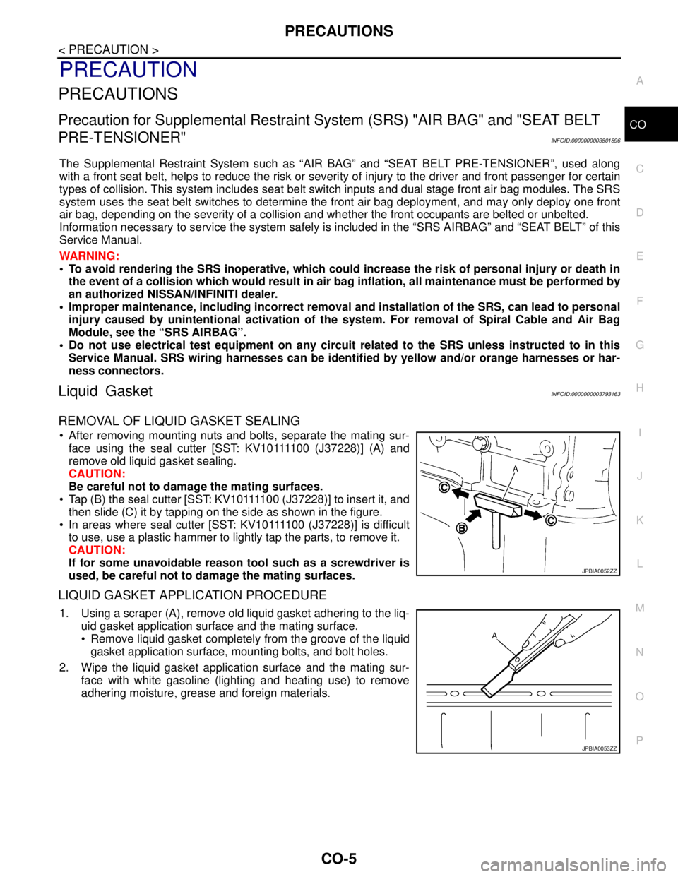
After removing mounting nuts and bolts, separate the mating sur-
f a c e u s i n g t h e s e a l c u t t e r [ S S T: K V 1 0 1111 0 0 ( J37228)] (A) and
remove old liquid gasket sealing.
CAUTION:
Be careful not to damage the mating surfaces.
Tap (B) the seal cutter [SST: KV10111100 (J37228)] to insert it, and
then slide (C) it by tapping on the side as shown in the figure.
In areas where seal cutter [SST: KV10111100 (J37228)] is difficult
to use, use a plastic hammer to lightly tap the parts, to remove it.
CAUTION:
If for some unavoidable reason tool such as a screwdriver is
used, be careful not to damage the mating surfaces.
LIQUID GASKET APPLICATION PROCEDURE
1. Using a scraper (A), remove old liquid gasket adhering to the liq-
uid gasket application surface and the mating surface.
Remove liquid gasket completely from the groove of the liquid
gasket application surface, mounting bolts, and bolt holes.
2. Wipe the liquid gasket application surface and the mating sur-
face with white gasoline (lighting and heating use) to remove
adhering moisture, grease and foreign materials.
JPBIA0052ZZ
JPBIA0053ZZ
Page 1131 of 5121
CO-8
< ON-VEHICLE MAINTENANCE >
ENGINE COOLANT
ON-VEHICLE MAINTENANCE
ENGINE COOLANT
InspectionINFOID:0000000003793166
LEVEL
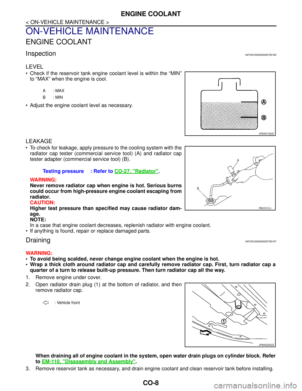
Check if the reservoir tank engine coolant level is within the “MIN”
to “MAX” when the engine is cool.
Adjust the engine coolant level as necessary.
LEAKAGE
To check for leakage, apply pressure to the cooling system with the
radiator cap tester (commercial service tool) (A) and radiator cap
tester adapter (commercial service tool) (B).
WARNING:
Never remove radiator cap when engine is hot. Serious burns
could occur from high-pressure engine coolant escaping from
radiator.
CAUTION:
Higher test pressure than specified may cause radiator dam-
age.
NOTE:
In a case that engine coolant decreases, replenish radiator with engine coolant.
If anything is found, repair or replace damaged parts.
DrainingINFOID:0000000003793167
WARNING:
To avoid being scalded, never change engine coolant when the engine is hot.
Wrap a thick cloth around radiator cap and carefully remove radiator cap. First, turn radiator cap a
quarter of a turn to release built-up pressure. Then turn radiator cap all the way.
1. Remove engine under cover.
2. Open radiator drain plug (1) at the bottom of radiator, and then
remove radiator cap.
When draining all of engine coolant in the system, open water drain plugs on cylinder block. Refer
to EM-110, "
Disassembly and Assembly".
3. Remove reservoir tank as necessary, and drain engine coolant and clean reservoir tank before installing.
A: MAX
B: MIN
JPBIA0102ZZ
Testing pressure : Refer to CO-27, "Radiator".
PBIC5121J
: Vehicle front
JPBIA2225ZZ
Page 1137 of 5121
CO-14
< ON-VEHICLE REPAIR >
RADIATOR
WARNING:
Never remove radiator cap when engine is hot. Serious burns could occur from high-pressure engine
coolant escaping from radiator. Wrap a thick cloth around the cap. Slowly turn it a quarter of a turn to
release built-up pressure. Carefully remove radiator cap by turning it all the way.
1. Remove the following parts:
Engine under cover.
Air duct (inlet): Refer to EM-26, "
Exploded View".
Horn: Refer to HRN-6, "
Exploded View".
Hood lock: Refer to DLK-220, "
Exploded View".
2. Drain engine coolant from radiator. Refer to CO-8, "
Draining".
CAUTION:
Perform this step when the engine is cold.
Never spill engine coolant on drive belt.
3. Disconnect reservoir tank hose from radiator pipe (upper).
4. Disconnect CVT fluid cooler hoses from radiator.
Install blind plug to avoid leakage of CVT fluid.
5. Disconnect Low-pressure flexible hose from lower pressure pipe, and then move it to aside. Refer to HA-
38, "Exploded View".
6. Remove radiator cap adapter and radiator hoses (upper) and radiator pipe (upper) assembly.
CAUTION:
Be careful not to allow engine coolant to contact drive belt.
7. Disconnect radiator hose (lower) from radiator.
8. Remove condenser. Refer to HA-46, "
Exploded View".
CAUTION:
Be careful not to damage condenser core.
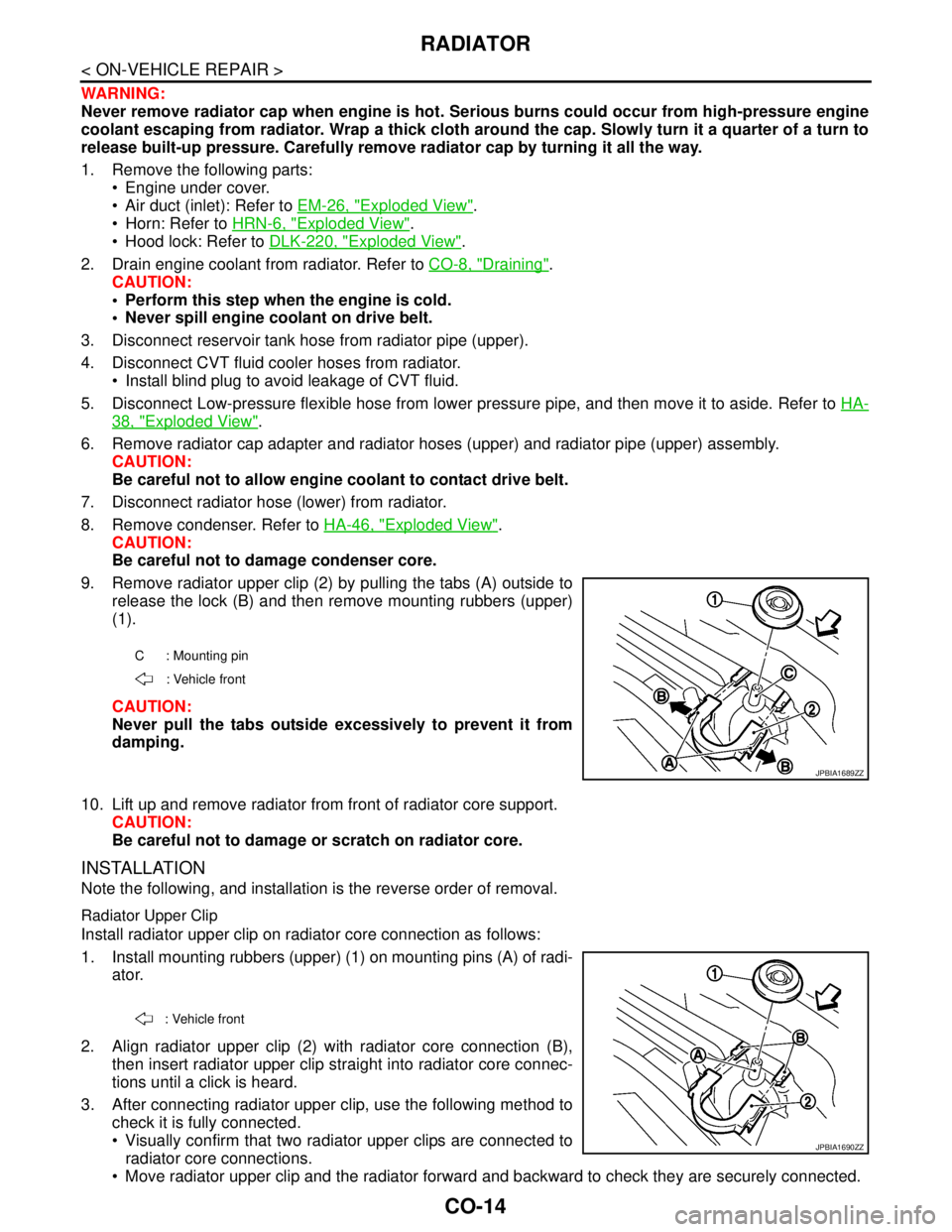
9. Remove radiator upper clip (2) by pulling the tabs (A) outside to
release the lock (B) and then remove mounting rubbers (upper)
(1).
CAUTION:
Never pull the tabs outside excessively to prevent it from
damping.
10. Lift up and remove radiator from front of radiator core support.
CAUTION:
Be careful not to damage or scratch on radiator core.
INSTALLATION
Note the following, and installation is the reverse order of removal.
Radiator Upper Clip
Install radiator upper clip on radiator core connection as follows:
1. Install mounting rubbers (upper) (1) on mounting pins (A) of radi-
ator.
2. Align radiator upper clip (2) with radiator core connection (B),
then insert radiator upper clip straight into radiator core connec-
tions until a click is heard.
3. After connecting radiator upper clip, use the following method to
check it is fully connected.
Visually confirm that two radiator upper clips are connected to
radiator core connections.
Move radiator upper clip and the radiator forward and backward to check they are securely connected.
C : Mounting pin
: Vehicle front
JPBIA1689ZZ
: Vehicle front
JPBIA1690ZZ
Page 1153 of 5121
DIAGNOSIS AND REPAIR WORKFLOW
DEF-3
< BASIC INSPECTION >
C
D
E
F
G
H
I
J
K
MA
B
DEF
N
O
P
BASIC INSPECTION
DIAGNOSIS AND REPAIR WORKFLOW
Work FlowINFOID:0000000003806024
DETAILED FLOW
1.OBTAIN INFORMATION ABOUT SYMPTOM
Interview the customer to obtain as much malfunction information (conditions and environment when the mal-
function occurred) as possible when the customer brings the vehicle in.
>> GO TO 2.
2.CHECK DTC
Perform self diagnosis with CONSULT-III
Is any DTC detected?
YES >> Refer to BCS-74, "DTCIndex"
NO >> GO TO 3.
3.REPRODUCE THE MALFUNCTION INFORMATION
Check the malfunction on the vehicle that the customer describes.
Inspect the relation of the symptoms and the condition when the symptoms occur.
>> GO TO 4.
4.IDENTIFY THE MALFUNCTIONING SYSTEM WITH “SYMPTOM DIAGNOSIS”
Use “Symptom diagnosis” from the symptom inspection result in step 3. Then identify where to start perform-
ing the diagnosis based on possible causes and symptoms.
>> GO TO 5.
5.IDENTIFY MALFUNCTIONING PARTS WITH “COMPONENT DIAGNOSIS”
Perform the diagnosis with “Component diagnosis” of the applicable system.
>> GO TO 6.
6.REPAIR OR REPLACE THE MALFUNCTIONING PARTS
Repair or replace the specified malfunctioning parts.
>> GO TO 7.
7.FINAL CHECK
Check that malfunctions are not reproduced when obtaining the malfunction information from the customer,
referring to the symptom inspection result in step 3.
Are all malfunctions corrected?
YES >> INSPECTION END
NO >> GO TO 4.
Page 1154 of 5121
DEF-4
< FUNCTION DIAGNOSIS >
REAR WINDOW DEFOGGER SYSTEM
FUNCTION DIAGNOSIS
REAR WINDOW DEFOGGER SYSTEM
WITH AV CONTROL UNIT
WITH AV CONTROL UNIT : System DiagramINFOID:0000000003806025
WITH AV CONTROL UNIT : System DescriptionINFOID:0000000003806026
Operation Description
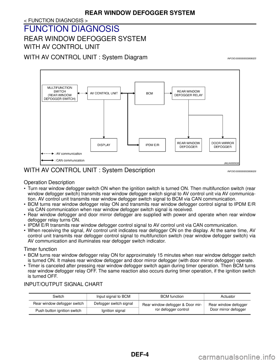
Turn rear window defogger switch ON when the ignition switch is turned ON. Then multifunction switch (rear
window defogger switch) transmits rear window defogger switch signal to AV control unit via AV communica-
tion. AV control unit transmits rear window defogger switch signal to BCM via CAN communication.
BCM turns rear window defogger relay ON and transmits rear window defogger control signal to IPDM E/R
via CAN communication when rear window defogger switch signal is received.
Rear window defogger and door mirror defogger are supplied with power and operate when rear window
defogger relay turns ON.
IPDM E/R transmits rear window defogger control signal to AV control unit via CAN communication.
When receiving the signal, AV control unit indicates rear defogger ON on the display. At the same time, AV
control unit transmits rear defogger control signal to multifunction switch (rear window defogger switch) via
AV communication and illuminates rear defogger switch indicator.
Timer function
BCM turns rear window defogger relay ON for approximately 15 minutes when rear window defogger switch
is turned ON. It makes rear window defogger and door mirror defogger (with door mirror defogger) operate.
Timer is canceled after pressing rear window defogger switch again during timer operation. Then BCM turns
rear window defogger relay OFF. The same reaction also occurs during timer operation, if the ignition switch
is turned OFF.
INPUT/OUTPUT SIGNAL CHART
JMLIA0005GB
Switch Input signal to BCM BCM function Actuator
Rear window defogger switch Defogger switch signal
Rear window defogger & Door mir-
ror defogger controlRear window defogger
Door mirror defogger
Push button ignition switch Ignition signal