2008 NISSAN LATIO engine
[x] Cancel search: enginePage 2361 of 2771
TROUBLE DIAGNOSIS
MTC-23
< SERVICE INFORMATION >
C
D
E
F
G
H
I
K
L
MA
B
MTC
N
O
P
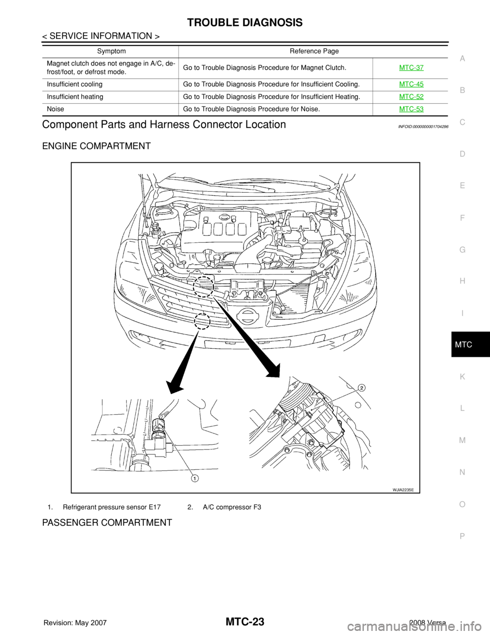
Component Parts and Harness Connector LocationINFOID:0000000001704296
ENGINE COMPARTMENT
PASSENGER COMPARTMENT
Magnet clutch does not engage in A/C, de-
frost/foot, or defrost mode.Go to Trouble Diagnosis Procedure for Magnet Clutch.MTC-37
Insufficient cooling Go to Trouble Diagnosis Procedure for Insufficient Cooling.MTC-45
Insufficient heating Go to Trouble Diagnosis Procedure for Insufficient Heating.MTC-52
Noise Go to Trouble Diagnosis Procedure for Noise.MTC-53
Symptom Reference Page
1. Refrigerant pressure sensor E17 2. A/C compressor F3
WJIA2235E
Page 2368 of 2771
MTC-30
< SERVICE INFORMATION >
TROUBLE DIAGNOSIS
Operational Check
INFOID:0000000001704300
The purpose of the operational check is to confirm that the system operates properly.
CHECKING BLOWER
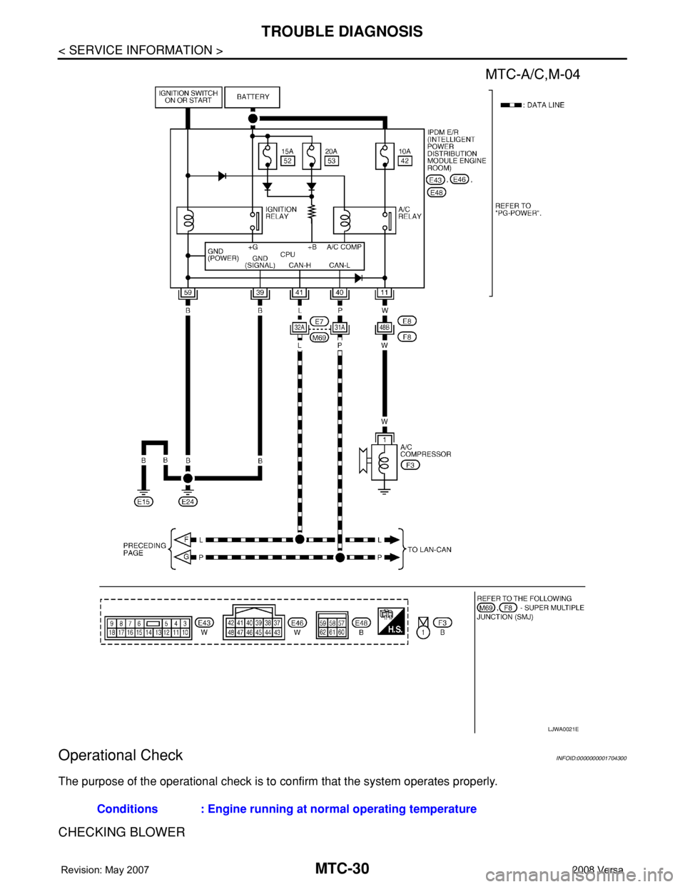
LJWA0021E
Conditions : Engine running at normal operating temperature
Page 2377 of 2771
TROUBLE DIAGNOSIS
MTC-39
< SERVICE INFORMATION >
C
D
E
F
G
H
I
K
L
MA
B
MTC
N
O
P
OK or NG
OK >> GO TO 3.
NG >> Check harness for open circuit. Repair or replace if necessary.
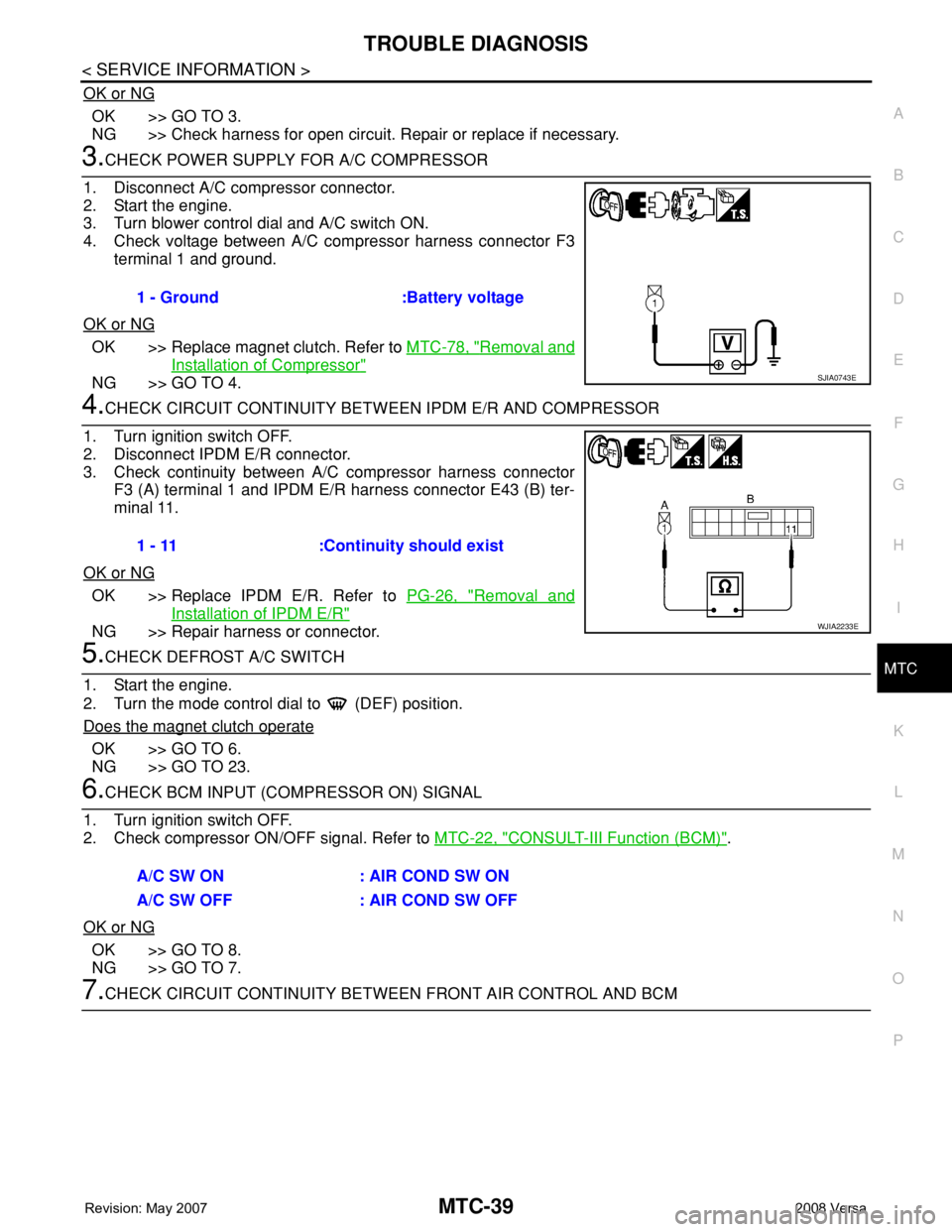
3.CHECK POWER SUPPLY FOR A/C COMPRESSOR
1. Disconnect A/C compressor connector.
2. Start the engine.
3. Turn blower control dial and A/C switch ON.
4. Check voltage between A/C compressor harness connector F3
terminal 1 and ground.
OK or NG
OK >> Replace magnet clutch. Refer to MTC-78, "Removal and
Installation of Compressor"
NG >> GO TO 4.
4.CHECK CIRCUIT CONTINUITY BETWEEN IPDM E/R AND COMPRESSOR
1. Turn ignition switch OFF.
2. Disconnect IPDM E/R connector.
3. Check continuity between A/C compressor harness connector
F3 (A) terminal 1 and IPDM E/R harness connector E43 (B) ter-
minal 11.
OK or NG
OK >> Replace IPDM E/R. Refer to PG-26, "Removal and
Installation of IPDM E/R"
NG >> Repair harness or connector.
5.CHECK DEFROST A/C SWITCH
1. Start the engine.
2. Turn the mode control dial to (DEF) position.
Does the magnet clutch operate
OK >> GO TO 6.
NG >> GO TO 23.
6.CHECK BCM INPUT (COMPRESSOR ON) SIGNAL
1. Turn ignition switch OFF.
2. Check compressor ON/OFF signal. Refer to MTC-22, "
CONSULT-III Function (BCM)".
OK or NG
OK >> GO TO 8.
NG >> GO TO 7.
7.CHECK CIRCUIT CONTINUITY BETWEEN FRONT AIR CONTROL AND BCM 1 - Ground :Battery voltage
SJIA0743E
1 - 11 :Continuity should exist
WJIA2233E
A/C SW ON : AIR COND SW ON
A/C SW OFF : AIR COND SW OFF
Page 2383 of 2771
TROUBLE DIAGNOSIS
MTC-45
< SERVICE INFORMATION >
C
D
E
F
G
H
I
K
L
MA
B
MTC
N
O
P
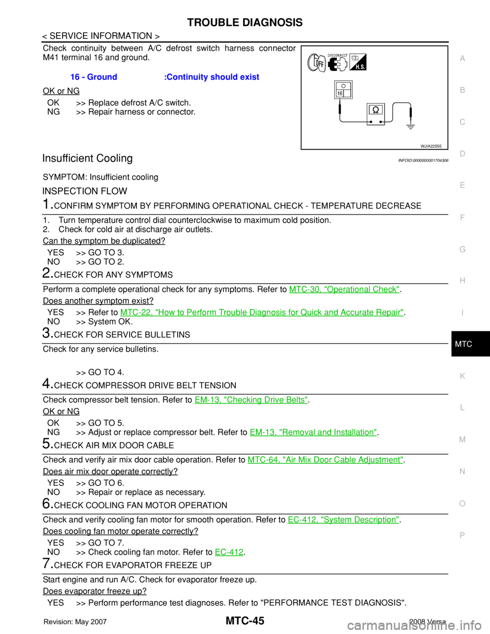
Check continuity between A/C defrost switch harness connector
M41 terminal 16 and ground.
OK or NG
OK >> Replace defrost A/C switch.
NG >> Repair harness or connector.
Insufficient CoolingINFOID:0000000001704306
SYMPTOM: Insufficient cooling
INSPECTION FLOW
1.CONFIRM SYMPTOM BY PERFORMING OPERATIONAL CHECK - TEMPERATURE DECREASE
1. Turn temperature control dial counterclockwise to maximum cold position.
2. Check for cold air at discharge air outlets.
Can the symptom be duplicated?
YES >> GO TO 3.
NO >> GO TO 2.
2.CHECK FOR ANY SYMPTOMS
Perform a complete operational check for any symptoms. Refer to MTC-30, "
Operational Check".
Does another symptom exist?
YES >> Refer to MTC-22, "How to Perform Trouble Diagnosis for Quick and Accurate Repair".
NO >> System OK.
3.CHECK FOR SERVICE BULLETINS
Check for any service bulletins.
>> GO TO 4.
4.CHECK COMPRESSOR DRIVE BELT TENSION
Check compressor belt tension. Refer to EM-13, "
Checking Drive Belts".
OK or NG
OK >> GO TO 5.
NG >> Adjust or replace compressor belt. Refer to EM-13, "
Removal and Installation".
5.CHECK AIR MIX DOOR CABLE
Check and verify air mix door cable operation. Refer to MTC-64, "
Air Mix Door Cable Adjustment".
Does air mix door operate correctly?
YES >> GO TO 6.
NO >> Repair or replace as necessary.
6.CHECK COOLING FAN MOTOR OPERATION
Check and verify cooling fan motor for smooth operation. Refer to EC-412, "
System Description".
Does cooling fan motor operate correctly?
YES >> GO TO 7.
NO >> Check cooling fan motor. Refer to EC-412
.
7.CHECK FOR EVAPORATOR FREEZE UP
Start engine and run A/C. Check for evaporator freeze up.
Does evaporator freeze up?
YES >> Perform performance test diagnoses. Refer to "PERFORMANCE TEST DIAGNOSIS". 16 - Ground :Continuity should exist
WJIA2255E
Page 2387 of 2771

TROUBLE DIAGNOSIS
MTC-49
< SERVICE INFORMATION >
C
D
E
F
G
H
I
K
L
MA
B
MTC
N
O
P Test Reading
Recirculating-to-discharge Air Temperature Table
Ambient Air Temperature-to-operating Pressure Table
*1: With blower control dial in the "1" position
*2: With blower control dial in the "4" position.
TROUBLE DIAGNOSIS FOR UNUSUAL PRESSURE
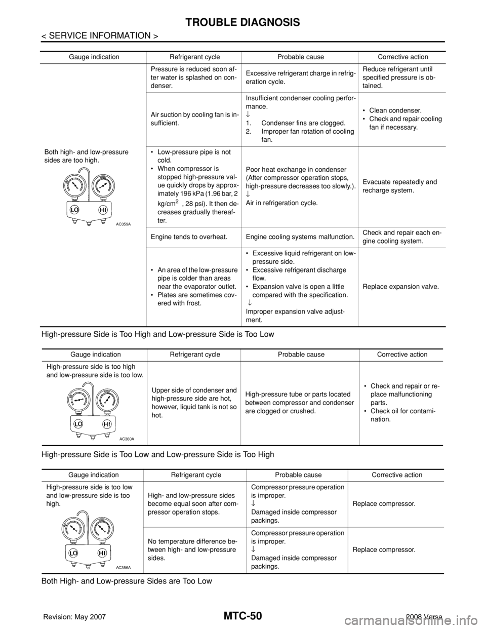
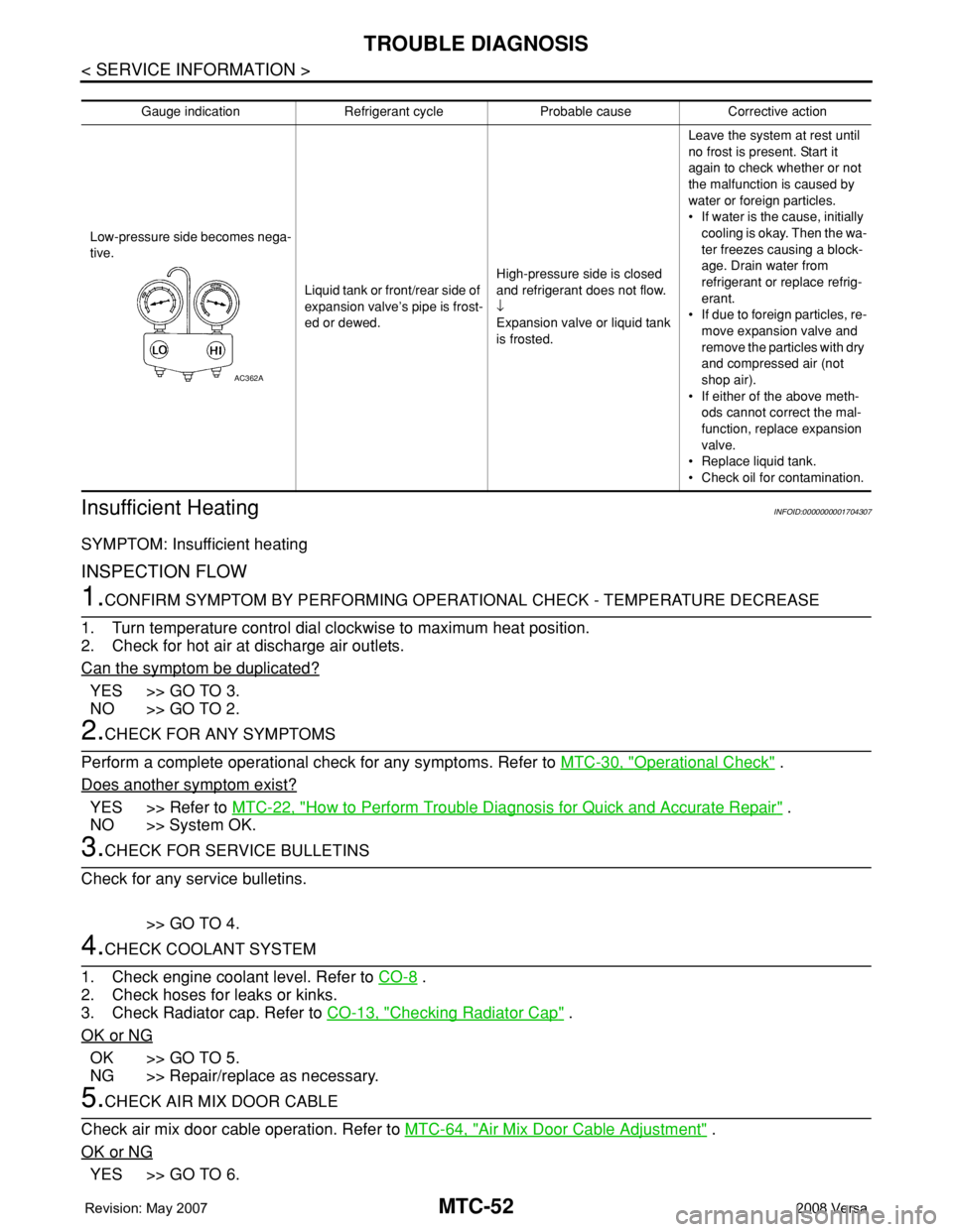
Whenever system’s high and/or low side pressure(s) is/are unusual, diagnose using a manifold gauge. The
marker above the gauge scale in the following tables indicates the standard (usual) pressure range. Since the
standard (usual) pressure, however, differs from vehicle to vehicle, refer to above table (Ambient air tempera-
ture-to-operating pressure table).
Both High- and Low-pressure Sides are Too High
TEMP. Max. COLD
Mode control dial
(Ventilation) set
Intake door lever
(Recirculation) set
Blower speedMax. speed set
Engine speed Idle speed
Operate the air conditioning system for 10 minutes before taking measurements.Vehicle condition Indoors or in the shade (in a well-ventilated place)
Inside air (Recirculating air) at blower assembly inlet
Discharge air temperature at center ventilator
°C (°F) Relative humidity
%Air temperature
°C (°F)
50 - 6020 (68) 7.2 - 9.1 (45 - 48)
25 (77) 11.4 - 13.8 (53 - 57)
30 (86) 15.5 - 18.4 (60 - 65)
35 (95) 20.3 - 23.7 (69 - 75)
60 - 7020 (68) 9.1 - 10.9 (48 - 52)
25 (77) 13.8 - 16.2 (57 - 61)
30 (86) 18.4 - 21.3 (65 - 70)
35 (95) 23.7 - 27.1 (75 - 81)
Ambient air
High-pressure (Discharge side)
kPa (bar, kg/cm
2 , psi)Low-pressure (Suction side)
kPa (bar, kg/cm2 , psi) Relative humidity
%Air temperature
°C (°F)
50 - 7020 (68)843 - 1,036 *1
(11.08 - 13.63, 8.6 - 10.6, 122 - 150)159.0 - 194.0
(1.59 - 1.94, 1.62 - 1.98, 23.1 - 28.1)
25 (77)1,094 - 1,338 *1
(10.94 - 13.38, 11.2 - 13.6, 159 - 194)196.3 - 240.0
(1.96 - 2.40, 2.00 - 2.45, 28.5 - 34.8)
30 (86)1,298 - 1,590 *1
(12.98 - 15.90, 13.2 - 16.2, 188 - 231)248.0 - 302.7
(2.48 - 3.03, 2.53 - 3.09, 36.0 - 43.9)
35 (95)1,383 - 1,688 *2
(13.83 - 16.88, 14.1 - 17.2, 201 - 245)308.8 - 377.4
(3.09 - 3.77, 3.15 - 3.85, 44.8 - 54.7)
40 (104)1,628 - 1,988 *2
(16.28 - 19.88, 16.6 - 20.3, 236 - 288)377.4 - 461.2
(3.77 - 4.61, 3.85 - 4.70, 54.7 - 66.8)
Page 2388 of 2771
MTC-50
< SERVICE INFORMATION >
TROUBLE DIAGNOSIS
High-pressure Side is Too High and Low-pressure Side is Too Low
High-pressure Side is Too Low and Low-pressure Side is Too High
Both High- and Low-pressure Sides are Too Low
Gauge indication Refrigerant cycle Probable cause Corrective action
Both high- and low-pressure
sides are too high.Pressure is reduced soon af-
ter water is splashed on con-
denser.Excessive refrigerant charge in refrig-
eration cycle.Reduce refrigerant until
specified pressure is ob-
tained.
Air suction by cooling fan is in-
sufficient.Insufficient condenser cooling perfor-
mance.
↓
1. Condenser fins are clogged.
2. Improper fan rotation of cooling
fan.• Clean condenser.
• Check and repair cooling
fan if necessary.
• Low-pressure pipe is not
cold.
• When compressor is
stopped high-pressure val-
ue quickly drops by approx-
imately 196 kPa (1.96 bar, 2
kg/cm
2 , 28 psi). It then de-
creases gradually thereaf-
ter.Poor heat exchange in condenser
(After compressor operation stops,
high-pressure decreases too slowly.).
↓
Air in refrigeration cycle.Evacuate repeatedly and
recharge system.
Engine tends to overheat. Engine cooling systems malfunction.Check and repair each en-
gine cooling system.
• An area of the low-pressure
pipe is colder than areas
near the evaporator outlet.
• Plates are sometimes cov-
ered with frost.• Excessive liquid refrigerant on low-
pressure side.
• Excessive refrigerant discharge
flow.
• Expansion valve is open a little
compared with the specification.
↓
Improper expansion valve adjust-
ment.Replace expansion valve.
AC359A
Gauge indication Refrigerant cycle Probable cause Corrective action
High-pressure side is too high
and low-pressure side is too low.
Upper side of condenser and
high-pressure side are hot,
however, liquid tank is not so
hot.High-pressure tube or parts located
between compressor and condenser
are clogged or crushed.• Check and repair or re-
place malfunctioning
parts.
• Check oil for contami-
nation.
AC360A
Gauge indication Refrigerant cycle Probable cause Corrective action
High-pressure side is too low
and low-pressure side is too
high.High- and low-pressure sides
become equal soon after com-
pressor operation stops.Compressor pressure operation
is improper.
↓
Damaged inside compressor
packings.Replace compressor.
No temperature difference be-
tween high- and low-pressure
sides.Compressor pressure operation
is improper.
↓
Damaged inside compressor
packings.Replace compressor.
AC356A
Page 2390 of 2771
MTC-52
< SERVICE INFORMATION >
TROUBLE DIAGNOSIS
Insufficient Heating
INFOID:0000000001704307
SYMPTOM: Insufficient heating
INSPECTION FLOW
1.CONFIRM SYMPTOM BY PERFORMING OPERATIONAL CHECK - TEMPERATURE DECREASE
1. Turn temperature control dial clockwise to maximum heat position.
2. Check for hot air at discharge air outlets.
Can the symptom be duplicated?
YES >> GO TO 3.
NO >> GO TO 2.
2.CHECK FOR ANY SYMPTOMS
Perform a complete operational check for any symptoms. Refer to MTC-30, "
Operational Check" .
Does another symptom exist?
YES >> Refer to MTC-22, "How to Perform Trouble Diagnosis for Quick and Accurate Repair" .
NO >> System OK.
3.CHECK FOR SERVICE BULLETINS
Check for any service bulletins.
>> GO TO 4.
4.CHECK COOLANT SYSTEM
1. Check engine coolant level. Refer to CO-8
.
2. Check hoses for leaks or kinks.
3. Check Radiator cap. Refer to CO-13, "
Checking Radiator Cap" .
OK or NG
OK >> GO TO 5.
NG >> Repair/replace as necessary.
5.CHECK AIR MIX DOOR CABLE
Check air mix door cable operation. Refer to MTC-64, "
Air Mix Door Cable Adjustment" .
OK or NG
YES >> GO TO 6.
Gauge indication Refrigerant cycle Probable cause Corrective action
Low-pressure side becomes nega-
tive.
Liquid tank or front/rear side of
expansion valve’s pipe is frost-
ed or dewed.High-pressure side is closed
and refrigerant does not flow.
↓
Expansion valve or liquid tank
is frosted.Leave the system at rest until
no frost is present. Start it
again to check whether or not
the malfunction is caused by
water or foreign particles.
• If water is the cause, initially
cooling is okay. Then the wa-
ter freezes causing a block-
age. Drain water from
refrigerant or replace refrig-
erant.
• If due to foreign particles, re-
move expansion valve and
remove the particles with dry
and compressed air (not
shop air).
• If either of the above meth-
ods cannot correct the mal-
function, replace expansion
valve.
• Replace liquid tank.
• Check oil for contamination.
AC362A
Page 2391 of 2771
TROUBLE DIAGNOSIS
MTC-53
< SERVICE INFORMATION >
C
D
E
F
G
H
I
K
L
MA
B
MTC
N
O
P
NO >> Adjust or replace air mix door cable. Refer to MTC-64, "Air Mix Door Cable Adjustment" .
6.CHECK AIR DUCTS
Check ducts for air leaks.
OK or NG
OK >> GO TO 7.
NG >> Repair air leaks.
7.CHECK HEATER HOSE TEMPERATURES
1. Start engine and warm it up to normal operating temperature.
2. Touch both the inlet and outlet heater hoses.
Is the inlet hose hot and the outlet hose warm?
YES >> GO TO 8.
NO >> Both hoses warm: GO TO 9.
8.CHECK ENGINE COOLANT TEMPERATURE SENSOR
Check engine control temperature sensor. Refer to EC-187
.
OK or NG
OK >> System OK.
NG >> Repair or replace as necessary. Retest.
9.CHECK HEATER HOSES
Check heater hoses for proper installation.
OK or NG
OK >> GO TO 10.
NG >> Repair /replace as necessary. Retest GO TO 7.
10.BACK FLUSH HEATER CORE
1. Back flush heater core.
2. Drain the water from the system.
3. Refill system with new engine coolant. Refer to CO-8, "
Changing Engine Coolant" .
4. Start engine and warm it up to normal operating temperature.
5. Touch both the inlet and outlet heater hoses.
Is the inlet hose hot and the outlet hose warm? YES or NO
YES >> System OK.
NO >> Replace heater core and refill engine coolant. Refer to MTC-67
.
NoiseINFOID:0000000001704308
SYMPTOM: Noise
INSPECTION FLOW