2008 NISSAN LATIO service indicator
[x] Cancel search: service indicatorPage 644 of 2771
BL-210
< SERVICE INFORMATION >
NATS (NISSAN ANTI-THEFT SYSTEM)
NATS (NISSAN ANTI-THEFT SYSTEM)
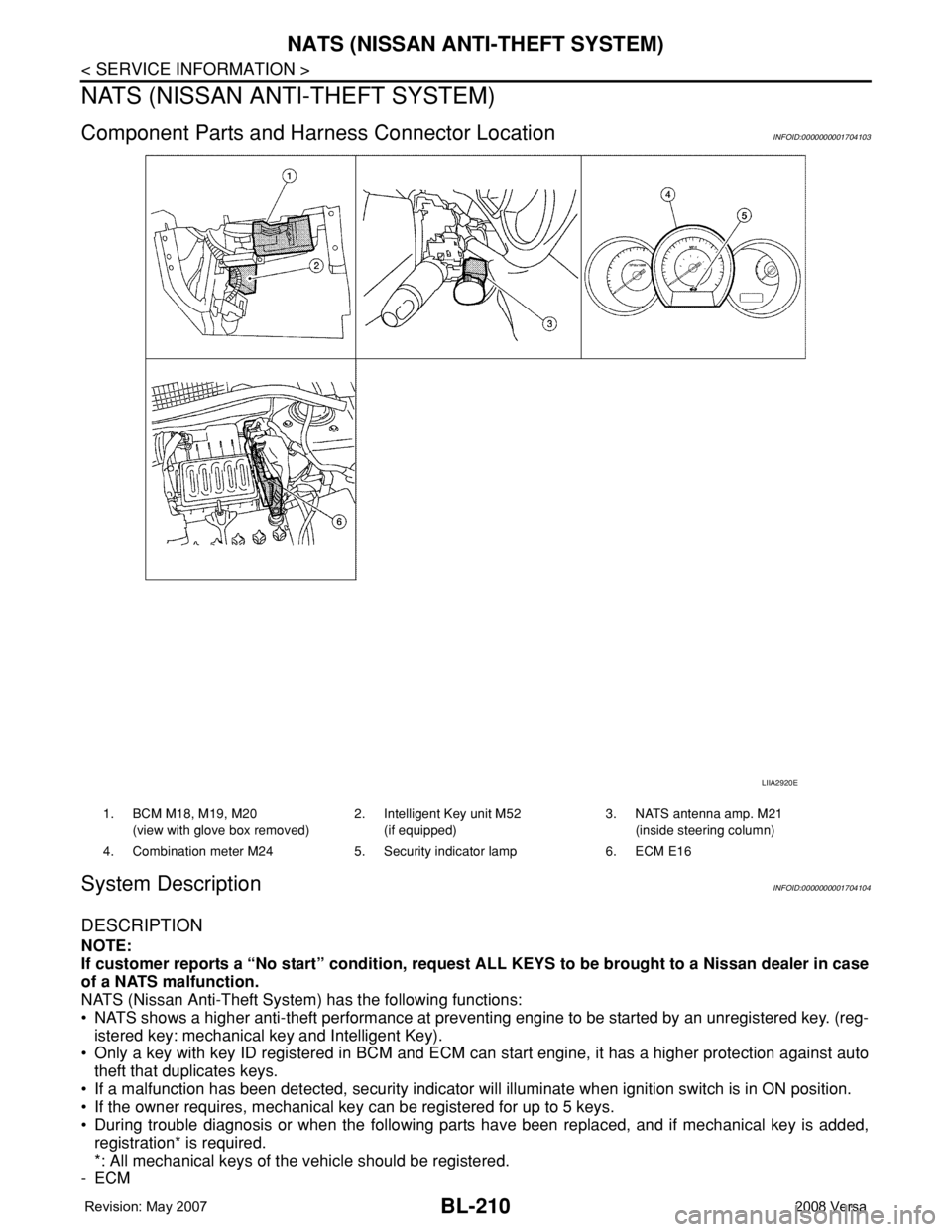
Component Parts and Harness Connector LocationINFOID:0000000001704103
System DescriptionINFOID:0000000001704104
DESCRIPTION
NOTE:
If customer reports a “No start” condition, request ALL KEYS to be brought to a Nissan dealer in case
of a NATS malfunction.
NATS (Nissan Anti-Theft System) has the following functions:
• NATS shows a higher anti-theft performance at preventing engine to be started by an unregistered key. (reg-
istered key: mechanical key and Intelligent Key).
• Only a key with key ID registered in BCM and ECM can start engine, it has a higher protection against auto
theft that duplicates keys.
• If a malfunction has been detected, security indicator will illuminate when ignition switch is in ON position.
• If the owner requires, mechanical key can be registered for up to 5 keys.
• During trouble diagnosis or when the following parts have been replaced, and if mechanical key is added,
registration* is required.
*: All mechanical keys of the vehicle should be registered.
-ECM
LIIA2920E
1. BCM M18, M19, M20
(view with glove box removed)2. Intelligent Key unit M52
(if equipped)3. NATS antenna amp. M21
(inside steering column)
4. Combination meter M24 5. Security indicator lamp 6. ECM E16
Page 645 of 2771
NATS (NISSAN ANTI-THEFT SYSTEM)
BL-211
< SERVICE INFORMATION >
C
D
E
F
G
H
J
K
L
MA
B
BL
N
O
P
-BCM
- Mechanical key
• NATS trouble diagnoses, system initialization and additional registration of other NATS mechanical key IDs
must be carried out using CONSULT-III hardware and CONSULT-III NATS software. When NATS initializa-
tion has been completed, the ID of the inserted mechanical key can be displayed.
Regarding the procedures of NATS initialization and mechanical key ID registration, refer to CONSULT-III
operation manual NATS.
SECURITY INDICATOR
• Forewarns that the vehicle is equipped with NATS.
• Security indicator will not blink while the ignition knob is in ON or START state.
NOTE:
Because security indicator is highly efficient, the battery is barely affected.
Condition of Security Indicator
• When operating the ignition switch with Intelligent Key, security indicator lamp will turn off at once if ignition
switch is pressed and blinks when ignition switch is released.
• When operating the ignition switch with mechanical key security indicator will turn off at once if mechanical
key is inserted into key cylinder and blinks when mechanical key is removed.
(Once the mechanical key is inserted into key cylinder, BCM will only perform the key ID verification with
mechanical key)
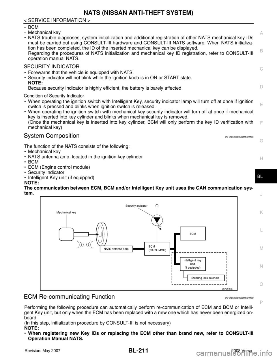
System CompositionINFOID:0000000001704105
The function of the NATS consists of the following:
• Mechanical key
• NATS antenna amp. located in the ignition key cylinder
•BCM
• ECM (Engine control module)
• Security indicator
• Intelligent Key unit (if equipped)
NOTE:
The communication between ECM, BCM and/or Intelligent Key unit uses the CAN communication sys-
tem.
ECM Re-communicating FunctionINFOID:0000000001704106
Performing the following procedure can automatically perform re-communication of ECM and BCM or Intelli-
gent Key unit, but only when the ECM has been replaced with a new one which has never been energized on-
board.
(In this step, initialization procedure by CONSULT-III is not necessary)
NOTE:
•When registering new Key IDs or replacing the ECM other than brand new, refer to CONSULT-III
Operation Manual NATS.
LIIA2637E
Page 652 of 2771

BL-218
< SERVICE INFORMATION >
NATS (NISSAN ANTI-THEFT SYSTEM)
Self-diagnosis related item
• *: When NATS detects trouble, the security indicator lights up while ignition key is in the “ON” position.
SYMPTOM MATRIX CHART 2
Non self-diagnosis related item
*: CONSULT-III self-diagnostic results display screen “no malfunction is detected”.
Diagnosis Procedure 1INFOID:0000000001704112
Self-diagnostic results:
“CHAIN OF ECM-IMMU” displayed on CONSULT-III screen
First perform the “SELF-DIAG RESULTS” in “BCM” with CONSULT-III, then perform the trouble diag-
nosis of malfunction system indicated “SELF-DIAG RESULTS” of “BCM”. Refer to BCS-17, "
CAN Com-
munication Inspection Using CONSULT-III (Self-Diagnosis)" .
1.CONFIRM SELF-DIAGNOSTIC RESULTS
Confirm SELF-DIAGNOSTIC RESULTS “CHAIN OF ECM-IMMU” displayed on CONSULT-III screen.
NOTE:
SYMPTOMDisplayed “SELF-DIAG
RESULTS” on CON-
SULT-III screen.DIAGNOSTIC PROCE-
DURE
(Reference page)SYSTEM
(Malfunctioning part or mode)
• Security indicator
lighting up*
• Engine cannot be
startedCHAIN OF ECM-IMMU
[P1612]PROCEDURE 1
(BL-218
)In rare case, “CHAIN OF ECM-IMMU” might be stored
during key registration procedure, even if the system is
not malfunctioning.
Open circuit in battery voltage line of BCM circuit
Open circuit in ignition line of BCM circuit
Open circuit in ground line of BCM circuit
Open or short circuit between BCM and ECM commu-
nication line
ECM
BCM
CHAIN OF IMMU-KEY
[P1614]PROCEDURE 2
(BL-220
)Malfunction of key ID chip
Communication line between ANT/ AMP and BCM:
Open circuit or short circuit of battery voltage line or
ground line
Open circuit in power source line of ANT/ AMP circuit
Open circuit in ground line of ANT/ AMP circuit
NATS antenna amp.
BCM
ID DISCORD, IMM-
ECM
[P1611]PROCEDURE 3
(BL-221
)System initialization has not yet been completed.
ECM
LOCK MODE
[P1610]PROCEDURE 5
(BL-223
)When the starting operation is carried out five or more
times consecutively under the following conditions,
NATS will shift the mode to one which prevents the en-
gine from being started.
• Unregistered ignition key is used.
• BCM or ECM’s malfunctioning.
Security indicator
lighting up*DON'T ERASE BE-
FORE CHECKING
ENG DIAGWORK FLOW
(BL-215
)Engine trouble data and NATS trouble data have been
detected in ECM
SYMPTOMDIAGNOSTIC PROCEDURE
(Reference page)SYSTEM
(Malfunctioning part or mode)
Security indicator does not light up*.PROCEDURE 4
(BL-222
)Security indictor.
Open circuit between Fuse and BCM
BCM
Page 657 of 2771
NATS (NISSAN ANTI-THEFT SYSTEM)
BL-223
< SERVICE INFORMATION >
C
D
E
F
G
H
J
K
L
MA
B
BL
N
O
P
OK or NG
OK >> BCM is malfunctioning.
• Replace BCM. Refer to BCS-18, "
Removal and Instal-
lation of BCM" .
• Perform initialization with CONSULT-III
• For initialization, refer to “CONSULT-III Operation
Manual NATS”
NG >> Check the following.
• Harness for open or short between combination meter (security) and BCM
• Indicator lamp condition
Diagnosis Procedure 5INFOID:0000000001704116
Self-diagnostic results:
“LOCK MODE” displayed on CONSULT-III screen
1.CONFIRM SELF-DIAGNOSTIC RESULTS
Confirm SELF-DIAGNOSTIC RESULTS “LOCK MODE” is displayed on CONSULT-III screen.
Is
“LOCK MODE” displayed?
Yes >> GO TO 2.
No >> GO TO BL-217, "
Trouble Diagnosis" .
2.ESCAPE FROM LOCK MODE
1. Turn ignition switch OFF.
2. Turn ignition switch ON with registered key. (Do not start engine.) Wait 5 seconds.
3. Return the key to OFF position. Wait 5 seconds.
4. Repeat steps 2 and 3 twice (total of three cycles).
5. Start the engine.
Does engine start?
Yes >> System is OK (Now system is escaped from “LOCK MODE”).
No >> GO TO 3.
3.PERFORM INITIALIZATION WITH CONSULT-III
Perform initialization with CONSULT-III.
For initialization, refer to “CONSULT-III Operation Manual NATS”.
NOTE:
If the initialization is not completed or malfunctions, CONSULT-III shows the message on the screen.
Can the system be initialized?
Yes >> System is OK.
No >> GO TO 4.
4.PERFORM INITIALIZATION WITH CONSULT-III AGAIN
1. Replace BCM.
2. Perform initialization with CONSULT-III.
For initialization, refer to “CONSULT-III Operation Manual NATS”.
NOTE:
If the initialization is not completed or malfunctions, CONSULT-III shows the message on the screen.
Can the system be initialized?
Yes >> System is OK. (BCM is malfunctioning.)
No >> ECM is malfunctioning.
• Replace ECM.
• Perform initialization with CONSULT-III
• For initialization, refer to “CONSULT-III Operation Manual NATS”
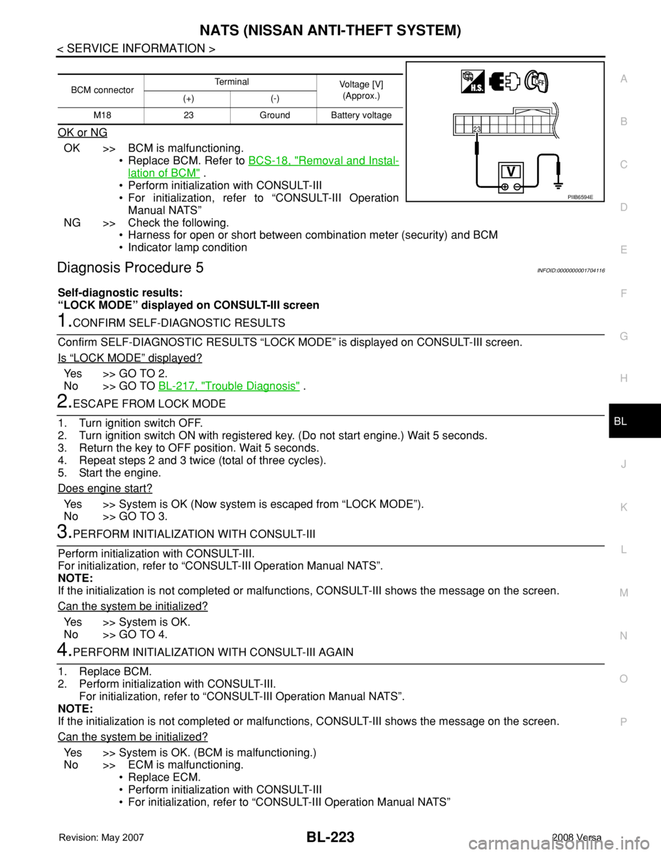
BCM connectorTerminal
Voltage [V]
(Approx.)
(+) (-)
M18 23 Ground Battery voltage
PIIB6594E
Page 752 of 2771
VACUUM LINES
BR-21
< SERVICE INFORMATION >
C
D
E
G
H
I
J
K
L
MA
B
BR
N
O
P
VACUUM LINES
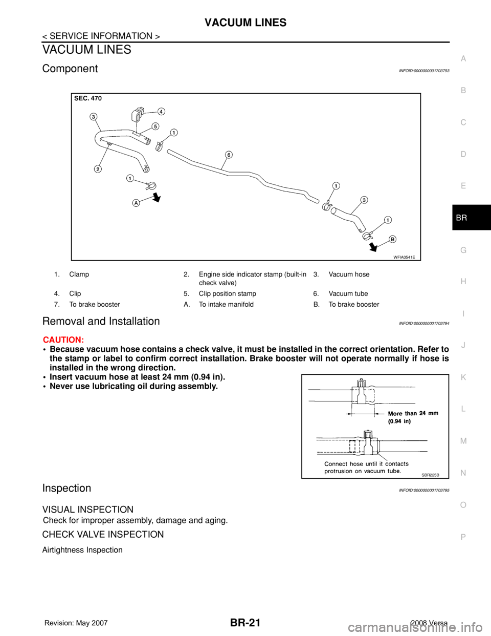
ComponentINFOID:0000000001703793
Removal and InstallationINFOID:0000000001703794
CAUTION:
• Because vacuum hose contains a check valve, it must be installed in the correct orientation. Refer to
the stamp or label to confirm correct installation. Brake booster will not operate normally if hose is
installed in the wrong direction.
• Insert vacuum hose at least 24 mm (0.94 in).
• Never use lubricating oil during assembly.
InspectionINFOID:0000000001703795
VISUAL INSPECTION
Check for improper assembly, damage and aging.
CHECK VALVE INSPECTION
Airtightness Inspection
1. Clamp 2. Engine side indicator stamp (built-in
check valve)3. Vacuum hose
4. Clip 5. Clip position stamp 6. Vacuum tube
7. To brake booster A. To intake manifold B. To brake booster
WFIA0541E
SBR225B
Page 758 of 2771
FRONT DISC BRAKE
BR-27
< SERVICE INFORMATION >
C
D
E
G
H
I
J
K
L
MA
B
BR
N
O
P
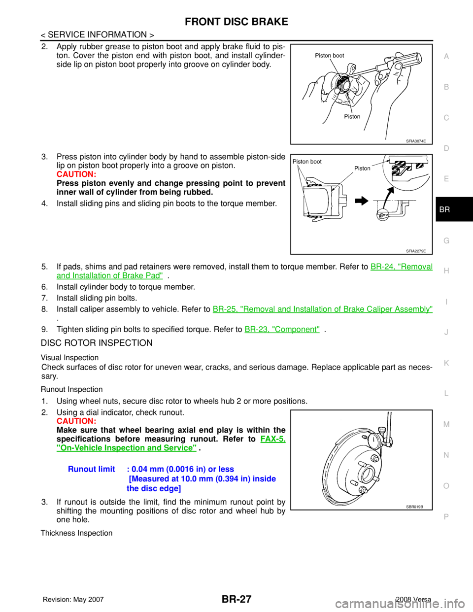
2. Apply rubber grease to piston boot and apply brake fluid to pis-
ton. Cover the piston end with piston boot, and install cylinder-
side lip on piston boot properly into groove on cylinder body.
3. Press piston into cylinder body by hand to assemble piston-side
lip on piston boot properly into a groove on piston.
CAUTION:
Press piston evenly and change pressing point to prevent
inner wall of cylinder from being rubbed.
4. Install sliding pins and sliding pin boots to the torque member.
5. If pads, shims and pad retainers were removed, install them to torque member. Refer to BR-24, "
Removal
and Installation of Brake Pad" .
6. Install cylinder body to torque member.
7. Install sliding pin bolts.
8. Install caliper assembly to vehicle. Refer to BR-25, "
Removal and Installation of Brake Caliper Assembly"
.
9. Tighten sliding pin bolts to specified torque. Refer to BR-23, "
Component" .
DISC ROTOR INSPECTION
Visual Inspection
Check surfaces of disc rotor for uneven wear, cracks, and serious damage. Replace applicable part as neces-
sary.
Runout Inspection
1. Using wheel nuts, secure disc rotor to wheels hub 2 or more positions.
2. Using a dial indicator, check runout.
CAUTION:
Make sure that wheel bearing axial end play is within the
specifications before measuring runout. Refer to FA X - 5 ,
"On-Vehicle Inspection and Service" .
3. If runout is outside the limit, find the minimum runout point by
shifting the mounting positions of disc rotor and wheel hub by
one hole.
Thickness Inspection
SFIA3074E
SFIA2279E
Runout limit : 0.04 mm (0.0016 in) or less
[Measured at 10.0 mm (0.394 in) inside
the disc edge]
SBR019B
Page 766 of 2771

BRC-1
BRAKES
C
D
E
G
H
I
J
K
L
M
SECTION BRC
A
B
BRC
N
O
P
CONTENTS
BRAKE CONTROL SYSTEM
ABS
SERVICE INFORMATION ............................
2
PRECAUTIONS ...................................................2
Precaution for Supplemental Restraint System
(SRS) "AIR BAG" and "SEAT BELT PRE-TEN-
SIONER" ...................................................................
2
Precaution for Brake System ....................................2
Precaution for Brake Control .....................................2
Precaution for CAN System ......................................3
PREPARATION ...................................................4
Special Service Tool .................................................4
Commercial Service Tool ..........................................4
SYSTEM DESCRIPTION .....................................5
System Component ...................................................5
ABS Function ............................................................5
EBD Function ............................................................5
Fail-Safe Function .....................................................5
Hydraulic Circuit Diagram .........................................6
CAN COMMUNICATION .....................................7
System Description ...................................................7
TROUBLE DIAGNOSIS ......................................8
How to Perform Trouble Diagnosis for Quick and
Accurate Repair ........................................................
8
Component Parts and Harness Connector Loca-
tion ..........................................................................
11
Schematic ...............................................................12
Wiring Diagram - ABS - ...........................................13
Basic Inspection ......................................................16
Warning Lamp and Indicator Timing ........................17
Control Unit Input/Output Signal Standard ..............17
CONSULT-III Function (ABS) ..................................18
TROUBLE DIAGNOSIS FOR SELF-DIAG-
NOSTIC ITEMS .................................................
24
Wheel Sensor System .............................................24
ABS Control Unit Inspection ....................................25
Solenoid Valve System Inspection ..........................25
Actuator Motor, Motor Relay, and Circuit Inspec-
tion ...........................................................................
26
ABS Control Unit Power and Ground Systems In-
spection ...................................................................
27
CAN Communication System Inspection .................28
TROUBLE DIAGNOSES FOR SYMPTOMS .....29
ABS Works Frequently ............................................29
Unexpected Pedal Action ........................................29
Long Stopping Distance ..........................................30
ABS Does Not Work ................................................30
Pedal Vibration or ABS Operation Noise .................30
WHEEL SENSORS ...........................................32
Removal and Installation .........................................32
SENSOR ROTOR ..............................................34
Removal and Installation .........................................34
ACTUATOR AND ELECTRIC UNIT (ASSEM-
BLY) ..................................................................
35
Removal and Installation .........................................35
Page 782 of 2771
![NISSAN LATIO 2008 Service Repair Manual TROUBLE DIAGNOSIS
BRC-17
< SERVICE INFORMATION >[ABS]
C
D
E
G
H
I
J
K
L
MA
B
BRC
N
O
P
• If ABS actuator and electric unit (control unit) connection is loose, tighten the piping to the specified
tor NISSAN LATIO 2008 Service Repair Manual TROUBLE DIAGNOSIS
BRC-17
< SERVICE INFORMATION >[ABS]
C
D
E
G
H
I
J
K
L
MA
B
BRC
N
O
P
• If ABS actuator and electric unit (control unit) connection is loose, tighten the piping to the specified
tor](/manual-img/5/57360/w960_57360-781.png)
TROUBLE DIAGNOSIS
BRC-17
< SERVICE INFORMATION >[ABS]
C
D
E
G
H
I
J
K
L
MA
B
BRC
N
O
P
• If ABS actuator and electric unit (control unit) connection is loose, tighten the piping to the specified
torque and recheck for leaks.
• If there is damage to the connection flare nut or ABS actuator and electric unit (control unit) threads,
replace the damaged part and recheck for leaks.
• When there is fluid leaking or seeping from a fluid connection, use a clean cloth to wipe off the fluid and
recheck for leaks. If fluid is still seeping out, replace the damaged part. If the fluid is leaking at the ABS
actuator and electric unit (control unit), replace the ABS actuator and electric unit (control unit) assem-
bly.
CAUTION:
The ABS actuator and electric unit (control unit) cannot be disassembled and must be replaced
as an assembly.
3. Check the brake pads for excessive wear.
POWER SYSTEM TERMINAL LOOSENESS AND BATTERY INSPECTION
Make sure the battery positive cable, negative cable and ground connection are not loose. In addition, make
sure the battery is sufficiently charged.
ABS WARNING LAMP INSPECTION
1. Make sure ABS warning lamp turns on for approximately 2 seconds when the ignition switch is turned ON.
If it does not, check CAN communications. If there are no errors with the CAN communication system,
replace the combination meter. Refer to IP-11, "
Removal and Installation".
2. Make sure the lamp turns off approximately 2 seconds after the ignition switch is turned ON. If the lamp
does not turn off, conduct self-diagnosis of ABS actuator and electric unit (control unit). If no malfunctions
are detected in self-diagnosis, replace combination meter. Refer to IP-11, "
Removal and Installation".
3. After conducting the self-diagnosis, be sure to erase the error memory. Refer to BRC-18, "
CONSULT-III
Function (ABS)".
Warning Lamp and Indicator TimingINFOID:0000000001703836
Note 1: Brake warning lamp will turn on when the parking brake is applied or when the brake fluid level is low.
x: ON
–: OFF
Control Unit Input/Output Signal StandardINFOID:0000000001703837
REFERENCE VALUE FROM CONSULT-III
CAUTION:
The display shows the control unit calculation data, so a normal value might be displayed even in the
event the output circuit (harness) is open or short circuited.
ConditionABS
warning lampBRAKE
warning lamp
[Note 1]Remarks
When the ignition switch is OFF – – –
After the ignition switch is turned ON for approx. 1
second××–
After the ignition switch is turned ON for approx. 2
seconds––Lamp goes off approx. 2 seconds after the
engine is started.
ABS malfunction×––
EBD malfunction××–